EP0310546A1 - Disposition variable de cadres de montage - Google Patents
Disposition variable de cadres de montage Download PDFInfo
- Publication number
- EP0310546A1 EP0310546A1 EP19880810616 EP88810616A EP0310546A1 EP 0310546 A1 EP0310546 A1 EP 0310546A1 EP 19880810616 EP19880810616 EP 19880810616 EP 88810616 A EP88810616 A EP 88810616A EP 0310546 A1 EP0310546 A1 EP 0310546A1
- Authority
- EP
- European Patent Office
- Prior art keywords
- profile
- mounting frame
- frame arrangement
- arrangement according
- legs
- Prior art date
- Legal status (The legal status is an assumption and is not a legal conclusion. Google has not performed a legal analysis and makes no representation as to the accuracy of the status listed.)
- Granted
Links
- 238000003892 spreading Methods 0.000 claims abstract description 9
- 238000006073 displacement reaction Methods 0.000 claims description 10
- 230000000903 blocking effect Effects 0.000 claims description 2
- 238000009434 installation Methods 0.000 abstract description 3
- 238000003860 storage Methods 0.000 abstract description 3
- 238000010276 construction Methods 0.000 abstract description 2
- 230000000694 effects Effects 0.000 description 3
- 239000002184 metal Substances 0.000 description 2
- 241001295925 Gegenes Species 0.000 description 1
- 238000005452 bending Methods 0.000 description 1
- 239000011230 binding agent Substances 0.000 description 1
- 238000005516 engineering process Methods 0.000 description 1
- 238000005304 joining Methods 0.000 description 1
- 238000004519 manufacturing process Methods 0.000 description 1
Images
Classifications
-
- F—MECHANICAL ENGINEERING; LIGHTING; HEATING; WEAPONS; BLASTING
- F16—ENGINEERING ELEMENTS AND UNITS; GENERAL MEASURES FOR PRODUCING AND MAINTAINING EFFECTIVE FUNCTIONING OF MACHINES OR INSTALLATIONS; THERMAL INSULATION IN GENERAL
- F16B—DEVICES FOR FASTENING OR SECURING CONSTRUCTIONAL ELEMENTS OR MACHINE PARTS TOGETHER, e.g. NAILS, BOLTS, CIRCLIPS, CLAMPS, CLIPS OR WEDGES; JOINTS OR JOINTING
- F16B7/00—Connections of rods or tubes, e.g. of non-circular section, mutually, including resilient connections
-
- F—MECHANICAL ENGINEERING; LIGHTING; HEATING; WEAPONS; BLASTING
- F16—ENGINEERING ELEMENTS AND UNITS; GENERAL MEASURES FOR PRODUCING AND MAINTAINING EFFECTIVE FUNCTIONING OF MACHINES OR INSTALLATIONS; THERMAL INSULATION IN GENERAL
- F16B—DEVICES FOR FASTENING OR SECURING CONSTRUCTIONAL ELEMENTS OR MACHINE PARTS TOGETHER, e.g. NAILS, BOLTS, CIRCLIPS, CLAMPS, CLIPS OR WEDGES; JOINTS OR JOINTING
- F16B12/00—Jointing of furniture or the like, e.g. hidden from exterior
- F16B12/10—Jointing of furniture or the like, e.g. hidden from exterior using pegs, bolts, tenons, clamps, clips, or the like
- F16B12/28—Jointing of furniture or the like, e.g. hidden from exterior using pegs, bolts, tenons, clamps, clips, or the like for metal furniture parts
- F16B12/36—Jointing of furniture or the like, e.g. hidden from exterior using pegs, bolts, tenons, clamps, clips, or the like for metal furniture parts using separate pins, dowels or the like
-
- F—MECHANICAL ENGINEERING; LIGHTING; HEATING; WEAPONS; BLASTING
- F16—ENGINEERING ELEMENTS AND UNITS; GENERAL MEASURES FOR PRODUCING AND MAINTAINING EFFECTIVE FUNCTIONING OF MACHINES OR INSTALLATIONS; THERMAL INSULATION IN GENERAL
- F16B—DEVICES FOR FASTENING OR SECURING CONSTRUCTIONAL ELEMENTS OR MACHINE PARTS TOGETHER, e.g. NAILS, BOLTS, CIRCLIPS, CLAMPS, CLIPS OR WEDGES; JOINTS OR JOINTING
- F16B7/00—Connections of rods or tubes, e.g. of non-circular section, mutually, including resilient connections
- F16B7/04—Clamping or clipping connections
- F16B7/044—Clamping or clipping connections for rods or tubes being in angled relationship
- F16B7/0446—Clamping or clipping connections for rods or tubes being in angled relationship for tubes using the innerside thereof
-
- F—MECHANICAL ENGINEERING; LIGHTING; HEATING; WEAPONS; BLASTING
- F16—ENGINEERING ELEMENTS AND UNITS; GENERAL MEASURES FOR PRODUCING AND MAINTAINING EFFECTIVE FUNCTIONING OF MACHINES OR INSTALLATIONS; THERMAL INSULATION IN GENERAL
- F16B—DEVICES FOR FASTENING OR SECURING CONSTRUCTIONAL ELEMENTS OR MACHINE PARTS TOGETHER, e.g. NAILS, BOLTS, CIRCLIPS, CLAMPS, CLIPS OR WEDGES; JOINTS OR JOINTING
- F16B2200/00—Constructional details of connections not covered for in other groups of this subclass
- F16B2200/67—Rigid angle couplings
-
- Y—GENERAL TAGGING OF NEW TECHNOLOGICAL DEVELOPMENTS; GENERAL TAGGING OF CROSS-SECTIONAL TECHNOLOGIES SPANNING OVER SEVERAL SECTIONS OF THE IPC; TECHNICAL SUBJECTS COVERED BY FORMER USPC CROSS-REFERENCE ART COLLECTIONS [XRACs] AND DIGESTS
- Y10—TECHNICAL SUBJECTS COVERED BY FORMER USPC
- Y10T—TECHNICAL SUBJECTS COVERED BY FORMER US CLASSIFICATION
- Y10T403/00—Joints and connections
- Y10T403/55—Member ends joined by inserted section
- Y10T403/555—Angle section
-
- Y—GENERAL TAGGING OF NEW TECHNOLOGICAL DEVELOPMENTS; GENERAL TAGGING OF CROSS-SECTIONAL TECHNOLOGIES SPANNING OVER SEVERAL SECTIONS OF THE IPC; TECHNICAL SUBJECTS COVERED BY FORMER USPC CROSS-REFERENCE ART COLLECTIONS [XRACs] AND DIGESTS
- Y10—TECHNICAL SUBJECTS COVERED BY FORMER USPC
- Y10T—TECHNICAL SUBJECTS COVERED BY FORMER US CLASSIFICATION
- Y10T403/00—Joints and connections
- Y10T403/55—Member ends joined by inserted section
- Y10T403/557—Expansible section
-
- Y—GENERAL TAGGING OF NEW TECHNOLOGICAL DEVELOPMENTS; GENERAL TAGGING OF CROSS-SECTIONAL TECHNOLOGIES SPANNING OVER SEVERAL SECTIONS OF THE IPC; TECHNICAL SUBJECTS COVERED BY FORMER USPC CROSS-REFERENCE ART COLLECTIONS [XRACs] AND DIGESTS
- Y10—TECHNICAL SUBJECTS COVERED BY FORMER USPC
- Y10T—TECHNICAL SUBJECTS COVERED BY FORMER US CLASSIFICATION
- Y10T403/00—Joints and connections
- Y10T403/70—Interfitted members
- Y10T403/7041—Interfitted members including set screw
Definitions
- the invention relates to a variable mounting frame arrangement with perforated square hollow profile sections and detachable connectors for two such profile sections, the connection being able to be established by means of an expansion effect on the connectors.
- Mounting frames of this type are e.g. in control panel construction, for racks and storage facilities, in house installation technology, for equipment cabinets etc. They are conventionally screwed together from perforated angle or U-profile sections, if necessary using special corner connectors.
- bolting together is quite time consuming, and protruding nuts and bolt heads can interfere with the use of the mounting frame.
- the profile sections at the corners they are offset from one another, that is to say they do not form any flat frames, and projecting profile corners or edges can represent a danger and also make use more difficult.
- two square hollow profiles with the same cross section can be connected at an angle and without overlap.
- the profiles to be connected are different in that one is provided with square windows on all four sides and the other with a longitudinal slot on one side (other sides closed) binder for this purpose has two blocks that are inserted lengthways into the slotted profile and can be expanded in it by means of a pressure screw.
- Two sheet metal lugs protruding from one of the blocks at any time engage from the outside in a window of the other profile.
- such a connection can hardly absorb any significant loads, since on the one hand there is practically only edge contact between the sheet metal tabs and the window and on the other hand the connector is inadequately secured against the effects of tension due to the expansion in the other profile.
- the object of the invention is to avoid the aforementioned disadvantages to create a versatile and highly resilient mounting frame arrangement, which manages with a single type of profile and as few different parts and can be assembled quickly and easily in many variations as required.
- the solution to this problem is that the square hollow profile is provided on one side with a longitudinal slot and at least on both adjacent sides with locking means against longitudinal displacement, and that the connectors have two pairs of legs provided with expansion elements, the width of which is transverse to the direction of expansion the internal profile width is adapted and which can each be inserted into the interior of a hollow profile section in order to engage existing locking elements with the locking means mentioned and then form fit with the four internal profile walls in the event of subsequent spreading on the outside of the legs.
- connection points of the hollow profile sections there are no overlaps or protruding parts at the connection points of the hollow profile sections.
- the connections achieve a high level of stability thanks to the form fit, and the profile sections are automatically aligned at right angles or parallel to each other after installation.
- connectors With appropriately designed connectors, both flat frames and spatial (three-dimensional) structures can be constructed. It comes with an astonishingly small number of different such parts and in particular with only one profile, which significantly simplifies the application, but also keeps the manufacturing and storage costs low.
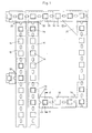
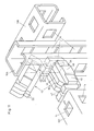
- the arrangement contains, as required, cut square hollow profile sections 10 which are rigidly but releasably connected to one another by means of corner connectors 20.
- corner connectors 20 can be inserted at any points along a given longitudinal division of the hollow profile and connected to one end of a profile section protruding at a right angle.
- intermediate frames can also be formed as required or parallel, adjacent profile sections can be used.
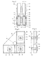
- the profile from which the sections 10 are made is a square hollow profile, preferably a square profile, the cross section of which can be seen in FIG. 2.
- One profile side 16 has a continuous longitudinal slot 12, while the two profile sides 18 adjoining the slotted side 16 are each provided with opposing, preferably square openings 14 in regular division.
- the side 19 opposite the slotted side 16 also expediently has openings 14 in the same division.
- the openings 14 form locking means against longitudinal displacements of the connectors 20 or 40 described below, which are provided with corresponding locking elements for engaging in the locking means.
- corner connectors 20 used here each consist of a pair of essentially identical parts, here angle pieces 22, the spacing of which can be changed by means of at least one expansion element 30 located between them; 2, 7 and 8, such spreading members are only indicated schematically with dash-dotted lines, expedient configurations are described below
- the two legs 24 connected at right angles to one another the angle pieces 22 can be inserted individually through the longitudinal slot 12 into the interior of the hollow profile 10 and then sit positively between the walls 16 and 19 of the profile section.
- the legs 24 are each provided with a cam 28 on their outer side 26. These cams are intended as locking members for engaging in openings 14 from the inside when the legs 24 are spread so far that their outer sides lie against the inside of the profile walls 18; the engagement of the cams 28 then prevents any longitudinal displacement between the connector and profile.
- the openings 14 and the cams 28 are preferably, as shown, square and fit into one another, but deviating shapes are also conceivable.
- the slot width s on the profile 10 is preferably selected to be equal to the side length of the square openings 14.
- the height of the cams 28 is at most equal to the profile wall thickness (FIG. 2), so that the cams do not protrude beyond the outside of the profile.
- each corner connector 20 has two expansion members 30, which are each arranged in the region of a pair of legs formed by two opposing legs 24.
- FIG. 3 it is possible, according to FIG. 3, with a single expansion member 30 'per corner connector, which acts simultaneously on all four legs or both pairs of legs of the connector.
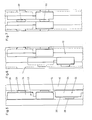
- 5 to 7 show the essential steps in the assembly of a corner connector on a profile section 10.
- one leg 24 of each corner piece 22 of the corner connector is first inserted through the slot 12 into the interior of the hollow profile, the two angle pieces being longitudinally offset from one another.
- the height h of the legs 24 including the locking member (cams 28) is slightly less than the width s of the slot 12 (see FIG. 2).
- one angle piece is laterally displaced, so that the outside 26 abuts the profile on the inserted leg and the cam 28 engages in an opening 14; the second angle piece 22 of the pair can then be moved in the longitudinal direction and brought to the same height as the first angle piece.
- the expansion element 30 is brought into effect between the legs 24 in the profile or their inner sides, so that both cams engage in opposite openings and the corner connector is firmly anchored to all four profile inner walls by positive locking.
- the other pair of legs of the corner connector then protrudes vertically from the profile section.
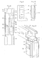
- a second profile section can then be joined together with these legs of the corner connector by temporarily pushing both angle pieces together again somewhat against the expansion element 30 and guiding the second profile section in the longitudinal direction from the end over the projecting legs.
- both pairs of legs of the corner connector are locked in the same way in a form-fitting manner and secured against longitudinal displacement with the two profile sections and the connection is rigid.
- FIGS. 9 and 10 Another (screwless) spreader is shown in FIGS. 9 and 10. It is formed by a corrugated leaf spring 38, which is attached to the inside of one leg 24. It automatically keeps the two associated legs inserted in the profile apart, but can be compressed from the outside in order to release the cam engagement.
- Other types of expansion elements 30 are e.g. in the form of wedges, eccentrics or the like. conceivable.
- Fig. 8 fastened, also on an angle connector 20 'another embodiment of locking means against longitudinal displacement instead of cams and openings.
- the hollow profile 10 '- at least on the side 16 adjacent to the longitudinal slot 12 sides 18 - on the inside a transverse to the longitudinal profile groove 15.
- the legs 24 of the connector 20 ' are provided on their outside with a transverse groove 29 which engages in contact with the inside of the profile in the groove 15 and thus prevents a longitudinal displacement between the connector and profile as a locking member.
- the profile 10 'with scoring 15 can be useful, although not shown in Fig. 8, also be provided with openings at least on the sides 18.
- 11 is another embodiment of a connector ders 40 shown
- This connector 40 also consists of two substantially identical parts 22 ', the distance between which can be varied by means of spreading elements, here two pressure screws 28. Deviating from the angle connector described so far here each part 22 ', however, two legs 24' aligned with each other in a straight line.
- the connector 40 is intended to connect two profile sections 10 in a straight line; 11, it is already inserted with one pair of legs in the lower profile section. The second section is then (when the parts 22 'are not spread) pushed from above in the direction of the arrow onto the second pair of legs, whereupon the form-fitting connection, which is secured against tensile load, is produced by spreading, here by means of pressure screws 32.
- Transverse grooves 15 and 29 according to FIG. 8 are then also conceivable as a blocking means against longitudinal displacement and corresponding latching members.
- the profile sections 10 can be joined to the connectors in any rotational position: As shown in FIG 11 shows that the longitudinal slot 12 on one section 10 can be offset by 90 ° to one or the other side from the longitudinal slot on the other section. The same is also possible with the angle connectors 20. As a result, not only frames lying in one plane according to FIG. 1, but also spatial frame structures can be assembled.
Landscapes
- Engineering & Computer Science (AREA)
- General Engineering & Computer Science (AREA)
- Mechanical Engineering (AREA)
- Mutual Connection Of Rods And Tubes (AREA)
- Assembled Shelves (AREA)
- Connection Of Plates (AREA)
- Joining Of Building Structures In Genera (AREA)
Applications Claiming Priority (2)
| Application Number | Priority Date | Filing Date | Title |
|---|---|---|---|
| CH3780/87 | 1987-09-29 | ||
| CH378087 | 1987-09-29 |
Publications (2)
| Publication Number | Publication Date |
|---|---|
| EP0310546A1 true EP0310546A1 (fr) | 1989-04-05 |
| EP0310546B1 EP0310546B1 (fr) | 1992-03-04 |
Family
ID=4263324
Family Applications (1)
| Application Number | Title | Priority Date | Filing Date |
|---|---|---|---|
| EP88810616A Expired - Lifetime EP0310546B1 (fr) | 1987-09-29 | 1988-09-12 | Disposition variable de cadres de montage |
Country Status (5)
| Country | Link |
|---|---|
| US (1) | US4896992A (fr) |
| EP (1) | EP0310546B1 (fr) |
| JP (1) | JPH01112008A (fr) |
| BR (1) | BR8805001A (fr) |
| DE (1) | DE3868822D1 (fr) |
Cited By (1)
| Publication number | Priority date | Publication date | Assignee | Title |
|---|---|---|---|---|
| US5090836A (en) * | 1991-01-15 | 1992-02-25 | Blake Hwang | Structure of a connecting joint of a case |
Families Citing this family (28)
| Publication number | Priority date | Publication date | Assignee | Title |
|---|---|---|---|---|
| US5144780A (en) * | 1991-03-25 | 1992-09-08 | Gieling Thomas G | Portable structure |
| US5423626A (en) * | 1993-03-22 | 1995-06-13 | The Fletcher-Terry Company | Clamping assembly |
| US5384978A (en) * | 1993-03-22 | 1995-01-31 | The Fletcher-Terry Company | Corner clamp assembly |
| US5411154A (en) * | 1993-09-13 | 1995-05-02 | Hardy Manufacturing, Inc. | System for joining support members |
| JP2693906B2 (ja) * | 1993-12-03 | 1997-12-24 | 日本電気エンジニアリング株式会社 | 通信装置取付枠 |
| US5431210A (en) * | 1994-02-10 | 1995-07-11 | Media/Graphics, Inc. | Panel retainers |
| US5785905A (en) * | 1995-09-11 | 1998-07-28 | Charles Chang | Method of making lipstick samplers |
| US5535555A (en) * | 1995-11-17 | 1996-07-16 | The University Foundation, California State University | Breakaway post coupling |
| US6058653A (en) * | 1996-07-19 | 2000-05-09 | Csb Enterprise, Inc. | Pivotable window sash assembly |
| US5768845A (en) * | 1996-10-04 | 1998-06-23 | Skyline Displays, Inc. | Module panel and assembly |
| AU5867498A (en) * | 1997-02-03 | 1998-09-08 | Tommi Ensio Ruusuvuori | Mounting method and -device for mounting rails |
| DE29717449U1 (de) * | 1997-09-30 | 1998-01-08 | Wismeth Wolfgang | Halterung für Solarmodule |
| US5890607A (en) * | 1997-10-06 | 1999-04-06 | Maglione; Stephen Thomas | Modular display |
| DE202004004734U1 (de) * | 2004-03-24 | 2005-09-08 | Kronenberg, Max | Mehrteiliger Steckverbinder |
| GB0412268D0 (en) * | 2004-06-03 | 2004-07-07 | Clive Smith Martin | Flat faced detent |
| TWM259213U (en) * | 2004-06-28 | 2005-03-11 | Tatung Co | Fixing sheet of sliding rail |
| US7849639B2 (en) * | 2004-11-02 | 2010-12-14 | Sprung Instant Structures Ltd. | Stressed membrane structure |
| US20080229699A1 (en) * | 2007-03-21 | 2008-09-25 | Unistrut International Corporation | Fittings for metal framing |
| CN101387130A (zh) * | 2007-09-11 | 2009-03-18 | 游柏森 | 建筑工业用槽件锚固装置 |
| CN102089601A (zh) * | 2008-05-08 | 2011-06-08 | 美国太阳能股份有限公司 | 安装于平屋顶的太阳能面板支架系统 |
| US20100122492A1 (en) * | 2008-11-14 | 2010-05-20 | C/S Construction Specialties Company | Shutter |
| US20130240008A1 (en) * | 2012-03-16 | 2013-09-19 | Christopher Baker | System and method for mounting photovoltaic modules |
| WO2017019719A2 (fr) * | 2015-07-27 | 2017-02-02 | Smash Solar, Inc. | Détection, interverrouillage d'un système de panneaux solaires et procédé d'installation |
| US9080792B2 (en) | 2013-07-31 | 2015-07-14 | Ironridge, Inc. | Method and apparatus for mounting solar panels |
| CN106049692B (zh) * | 2016-07-29 | 2018-02-27 | 浙江飞屋建筑科技有限公司 | 一种轻钢房屋连接结构 |
| US11241092B1 (en) * | 2020-09-09 | 2022-02-08 | Taiwan Shin Yeh Enterprise Co., Ltd. | Modular post assembly for a shelf storage rack |
| DE202021102093U1 (de) | 2021-04-19 | 2021-06-08 | apra-norm Elektromechanik GmbH | Verbindungselement zum Verbinden eines Hohlprofils mit einem weiteren Bauteil |
| FI130136B (en) * | 2021-12-07 | 2023-03-09 | Acon Finland Oy Ltd | Basketball hoop structure for trampoline |
Citations (4)
| Publication number | Priority date | Publication date | Assignee | Title |
|---|---|---|---|---|
| FR1304947A (fr) * | 1961-11-03 | 1962-09-28 | Nouveau dispositif pour la réalisation de rayonnages en porte-à-faux | |
| CH376623A (de) * | 1959-11-23 | 1964-04-15 | Schmid Peter | Gestell aus Profilstücken, die mindestens zum Teil lösbar und verstellbar miteinander verbunden sind |
| AT295406B (de) * | 1968-11-28 | 1972-01-10 | Leopold Osthoff | Gestell, insbesondere Lagergestell |
| FR2261690A5 (en) * | 1973-10-23 | 1975-09-12 | Sperry Rand Corp | Joint for tubular framework - adaptor inside tube end tensioned by screw to lock lugs in slots in adjacent member |
Family Cites Families (10)
| Publication number | Priority date | Publication date | Assignee | Title |
|---|---|---|---|---|
| DE295406C (fr) * | ||||
| US3368836A (en) * | 1965-09-27 | 1968-02-13 | Deco Products Company | Joint construction including connector |
| US3513606A (en) * | 1968-02-21 | 1970-05-26 | Vernon H Jones | Structural framework and connector joint therefor |
| US3620558A (en) * | 1969-06-23 | 1971-11-16 | Daniel G Macmillan | Joint locking apparatus |
| DE2618442C2 (de) * | 1976-04-27 | 1986-10-09 | Gebrüder Kömmerling Kunststoffwerke GmbH, 6780 Pirmasens | Stütze für ein Geländer oder dergleichen |
| US4317523A (en) * | 1979-10-12 | 1982-03-02 | Speedshelf International, Inc. | Storage structure having two-piece beams |
| GB2140280A (en) * | 1983-04-26 | 1984-11-28 | Imhof Bedco Standard Products | Electronic rack |
| IT1201340B (it) * | 1985-08-07 | 1989-01-27 | Giampaolo Targetti | Morsetto ad espansione per il collegamento di estremita' concorrenti di componenti cavi di strutture reticolari ed altro |
| JPH0117686Y2 (fr) * | 1985-11-25 | 1989-05-23 | ||
| EP0346948B1 (fr) * | 1985-12-02 | 1994-01-12 | Entwurf Partner Ruedi Zwissler | Ossature constituée d'élements en forme de barre |
-
1988
- 1988-09-12 EP EP88810616A patent/EP0310546B1/fr not_active Expired - Lifetime
- 1988-09-12 DE DE8888810616T patent/DE3868822D1/de not_active Expired - Fee Related
- 1988-09-27 BR BR8805001A patent/BR8805001A/pt not_active IP Right Cessation
- 1988-09-29 JP JP63242664A patent/JPH01112008A/ja active Granted
- 1988-09-29 US US07/251,118 patent/US4896992A/en not_active Expired - Fee Related
Patent Citations (4)
| Publication number | Priority date | Publication date | Assignee | Title |
|---|---|---|---|---|
| CH376623A (de) * | 1959-11-23 | 1964-04-15 | Schmid Peter | Gestell aus Profilstücken, die mindestens zum Teil lösbar und verstellbar miteinander verbunden sind |
| FR1304947A (fr) * | 1961-11-03 | 1962-09-28 | Nouveau dispositif pour la réalisation de rayonnages en porte-à-faux | |
| AT295406B (de) * | 1968-11-28 | 1972-01-10 | Leopold Osthoff | Gestell, insbesondere Lagergestell |
| FR2261690A5 (en) * | 1973-10-23 | 1975-09-12 | Sperry Rand Corp | Joint for tubular framework - adaptor inside tube end tensioned by screw to lock lugs in slots in adjacent member |
Cited By (1)
| Publication number | Priority date | Publication date | Assignee | Title |
|---|---|---|---|---|
| US5090836A (en) * | 1991-01-15 | 1992-02-25 | Blake Hwang | Structure of a connecting joint of a case |
Also Published As
| Publication number | Publication date |
|---|---|
| US4896992A (en) | 1990-01-30 |
| EP0310546B1 (fr) | 1992-03-04 |
| BR8805001A (pt) | 1989-05-02 |
| JPH0574722B2 (fr) | 1993-10-19 |
| JPH01112008A (ja) | 1989-04-28 |
| DE3868822D1 (de) | 1992-04-09 |
Similar Documents
| Publication | Publication Date | Title |
|---|---|---|
| EP0310546B1 (fr) | Disposition variable de cadres de montage | |
| DE10136681A1 (de) | Rahmengestell | |
| DE3200310A1 (de) | Gestell aus mehreren profilstaeben | |
| EP0369326B1 (fr) | Dispositif isolant de liaison pour panneaux de construction | |
| DE3729903C2 (fr) | ||
| DE3603453C2 (fr) | ||
| DE3616031C2 (fr) | ||
| DE3728247C1 (de) | Verbundprofil fuer Rahmenschenkel oder Sprossen | |
| DE4227532C2 (de) | Rahmenprofil für das Rahmengestell eines Schaltschrankes | |
| DE2516182C2 (de) | Knotenpunkt aus mindestens zwei im Querschnitt rechteckigen Profilstäben | |
| EP0773615B1 (fr) | Armoire de commutation pour installation électrique | |
| DE2724201A1 (de) | Moebelbausystem oder -bausatz | |
| DE2516264C2 (de) | Befestigungsvorrichtung für ein Beschlagteil an Profilstäben aus Metall oder Kunststoff | |
| DE2654239A1 (de) | Schaltschrank mit einem aus profilstaeben hergestellten geruest | |
| DE2644040C2 (de) | Winkelverbindung für Bauteile, insbesondere Profilleisten, Profilträger u.dgl. | |
| DE3442231A1 (de) | Raumkonstruktion | |
| EP0846814B1 (fr) | Rail de montage | |
| EP3299531B1 (fr) | Dalle de plafond de faux-plafond avec élément de verrouillage activable sans outil | |
| DE102006059750A1 (de) | Möbelverkettungselement, Möbel und Montageverfahren | |
| DE4227531C2 (de) | Eckverbinder für ein Rahmengestell eines Schaltschrankes | |
| DE1658918B1 (de) | Versetzbare Trennwand | |
| DE102004013631A1 (de) | Profilkonstruktion | |
| DE2153997C3 (de) | Bauelementensatz zur Montage von Verkleidungsplatten an einer Wand bzw. für eine Trennwand | |
| DE2408185A1 (de) | Zerlegbare trennwand | |
| DE2552983A1 (de) | Spannvorrichtung zum verbinden von geraetegehaeusen o.dgl. |
Legal Events
| Date | Code | Title | Description |
|---|---|---|---|
| PUAI | Public reference made under article 153(3) epc to a published international application that has entered the european phase |
Free format text: ORIGINAL CODE: 0009012 |
|
| AK | Designated contracting states |
Kind code of ref document: A1 Designated state(s): CH DE FR GB IT LI SE |
|
| 17P | Request for examination filed |
Effective date: 19890809 |
|
| 17Q | First examination report despatched |
Effective date: 19900621 |
|
| RAP3 | Party data changed (applicant data changed or rights of an application transferred) |
Owner name: LANZ OENSINGEN AG |
|
| GRAA | (expected) grant |
Free format text: ORIGINAL CODE: 0009210 |
|
| ITF | It: translation for a ep patent filed |
Owner name: FUMERO BREVETTI S.N.C. |
|
| AK | Designated contracting states |
Kind code of ref document: B1 Designated state(s): CH DE FR GB IT LI SE |
|
| REF | Corresponds to: |
Ref document number: 3868822 Country of ref document: DE Date of ref document: 19920409 |
|
| ET | Fr: translation filed | ||
| GBT | Gb: translation of ep patent filed (gb section 77(6)(a)/1977) | ||
| PLBE | No opposition filed within time limit |
Free format text: ORIGINAL CODE: 0009261 |
|
| STAA | Information on the status of an ep patent application or granted ep patent |
Free format text: STATUS: NO OPPOSITION FILED WITHIN TIME LIMIT |
|
| 26N | No opposition filed | ||
| EAL | Se: european patent in force in sweden |
Ref document number: 88810616.8 |
|
| PGFP | Annual fee paid to national office [announced via postgrant information from national office to epo] |
Ref country code: FR Payment date: 19990820 Year of fee payment: 12 |
|
| PGFP | Annual fee paid to national office [announced via postgrant information from national office to epo] |
Ref country code: CH Payment date: 19990823 Year of fee payment: 12 |
|
| PGFP | Annual fee paid to national office [announced via postgrant information from national office to epo] |
Ref country code: GB Payment date: 19990902 Year of fee payment: 12 |
|
| PGFP | Annual fee paid to national office [announced via postgrant information from national office to epo] |
Ref country code: DE Payment date: 19990914 Year of fee payment: 12 |
|
| PGFP | Annual fee paid to national office [announced via postgrant information from national office to epo] |
Ref country code: SE Payment date: 19990922 Year of fee payment: 12 |
|
| PG25 | Lapsed in a contracting state [announced via postgrant information from national office to epo] |
Ref country code: GB Free format text: LAPSE BECAUSE OF NON-PAYMENT OF DUE FEES Effective date: 20000912 |
|
| PG25 | Lapsed in a contracting state [announced via postgrant information from national office to epo] |
Ref country code: SE Free format text: THE PATENT HAS BEEN ANNULLED BY A DECISION OF A NATIONAL AUTHORITY Effective date: 20000929 |
|
| PG25 | Lapsed in a contracting state [announced via postgrant information from national office to epo] |
Ref country code: LI Free format text: LAPSE BECAUSE OF NON-PAYMENT OF DUE FEES Effective date: 20000930 Ref country code: CH Free format text: LAPSE BECAUSE OF NON-PAYMENT OF DUE FEES Effective date: 20000930 |
|
| GBPC | Gb: european patent ceased through non-payment of renewal fee |
Effective date: 20000912 |
|
| REG | Reference to a national code |
Ref country code: CH Ref legal event code: PL |
|
| EUG | Se: european patent has lapsed |
Ref document number: 88810616.8 |
|
| PG25 | Lapsed in a contracting state [announced via postgrant information from national office to epo] |
Ref country code: FR Free format text: LAPSE BECAUSE OF NON-PAYMENT OF DUE FEES Effective date: 20010531 |
|
| PG25 | Lapsed in a contracting state [announced via postgrant information from national office to epo] |
Ref country code: DE Free format text: LAPSE BECAUSE OF NON-PAYMENT OF DUE FEES Effective date: 20010601 |
|
| REG | Reference to a national code |
Ref country code: FR Ref legal event code: ST |
|
| PG25 | Lapsed in a contracting state [announced via postgrant information from national office to epo] |
Ref country code: IT Free format text: LAPSE BECAUSE OF NON-PAYMENT OF DUE FEES;WARNING: LAPSES OF ITALIAN PATENTS WITH EFFECTIVE DATE BEFORE 2007 MAY HAVE OCCURRED AT ANY TIME BEFORE 2007. THE CORRECT EFFECTIVE DATE MAY BE DIFFERENT FROM THE ONE RECORDED. Effective date: 20050912 |