EP0310418A2 - Appareil magnétique d'enregistrement et de reproduction - Google Patents
Appareil magnétique d'enregistrement et de reproduction Download PDFInfo
- Publication number
- EP0310418A2 EP0310418A2 EP88309104A EP88309104A EP0310418A2 EP 0310418 A2 EP0310418 A2 EP 0310418A2 EP 88309104 A EP88309104 A EP 88309104A EP 88309104 A EP88309104 A EP 88309104A EP 0310418 A2 EP0310418 A2 EP 0310418A2
- Authority
- EP
- European Patent Office
- Prior art keywords
- signal
- frequency
- recording
- reproducing
- reproduced
- Prior art date
- Legal status (The legal status is an assumption and is not a legal conclusion. Google has not performed a legal analysis and makes no representation as to the accuracy of the status listed.)
- Withdrawn
Links
Images

Classifications
-
- G—PHYSICS
- G11—INFORMATION STORAGE
- G11B—INFORMATION STORAGE BASED ON RELATIVE MOVEMENT BETWEEN RECORD CARRIER AND TRANSDUCER
- G11B15/00—Driving, starting or stopping record carriers of filamentary or web form; Driving both such record carriers and heads; Guiding such record carriers or containers therefor; Control thereof; Control of operating function
- G11B15/02—Control of operating function, e.g. switching from recording to reproducing
-
- H—ELECTRICITY
- H04—ELECTRIC COMMUNICATION TECHNIQUE
- H04N—PICTORIAL COMMUNICATION, e.g. TELEVISION
- H04N5/00—Details of television systems
- H04N5/76—Television signal recording
- H04N5/91—Television signal processing therefor
- H04N5/92—Transformation of the television signal for recording, e.g. modulation, frequency changing; Inverse transformation for playback
-
- G—PHYSICS
- G11—INFORMATION STORAGE
- G11B—INFORMATION STORAGE BASED ON RELATIVE MOVEMENT BETWEEN RECORD CARRIER AND TRANSDUCER
- G11B5/00—Recording by magnetisation or demagnetisation of a record carrier; Reproducing by magnetic means; Record carriers therefor
- G11B5/02—Recording, reproducing, or erasing methods; Read, write or erase circuits therefor
- G11B5/027—Analogue recording
-
- H—ELECTRICITY
- H04—ELECTRIC COMMUNICATION TECHNIQUE
- H04N—PICTORIAL COMMUNICATION, e.g. TELEVISION
- H04N5/00—Details of television systems
- H04N5/76—Television signal recording
- H04N5/91—Television signal processing therefor
- H04N5/911—Television signal processing therefor for the suppression of noise
Definitions
- the present invention relates to a magnetic recording and reproducing apparatus such as a video tape recorder.
- FM frequency modulation
- S/N ratio signal/noise ratio
- An object of the present invention is to obtain improvement in S/N ratio and frequency characteristics by enlarging the amount of increase in the level of the lower sideband of the reproduced FM signal.
- the magnetic recording and reproducing apparatus of the present invention is provided with a circuit which attenuates at least one of the upper sideband components of an FM signal before recording the FM signal on a recording medium.
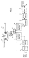
- a video signal is inputted to an input terminal 1, and converted into an FM signal having a frequency deviation range of for example 5.4 MHz ⁇ 7.0 MHz in a frequency modulation circuit (FMOD) 2.
- FMOD frequency modulation circuit
- the FM signal is subjected to attenuation in the upper sideband with a filter circuit 3, and sent via a recording amplifier 4 to a selection switch 5 for selection between recording and reproducing.
- the selection switch 5 is connected to R side, the output signal of the recording amplifier 4 is supplied to magnetic heads 10, 11 through rotary transformers 6, 7, and recorded on a magnetic tape 12.
- the magnetic heads are mounted on a rotary disk 9 which is rotated at a prescribed speed by a motor (not illustrated) connected to a rotary shaft 8.
- the magnetic tape 12 is wound around the rotary disk 9 over 180°, and caused to run at a prescribed speed in the direction of an arrow 13 by means of a well known magnetic tape driving mechanism including a capstan, pinch rollers, etc.
- the recorded signal is reproduced by the magnetic heads 10, 11.
- This reproduced signal contains the upper sideband components produced by non-linearity of the frequency characteristics of electromagnetic conversion system constituted by the head and the tape.
- the reproduced signal is fed via a repoducing amplifier 14 to an RF equalizer 15 which adjusts the level of the lower sideband components of the reproduced FM signal.
- the noise level is also reduced in proportion to the reduction amount of the lower sideband component level.
- the output of the RF equalizer 15 is attenuated of its upper sideband components by a filter circuit 16, and then demodulated with a frequency demodulator (FDEM) 17.
- FDEM frequency demodulator
- the frequency modulation circuit 2 and the frequency demodulation circuit 17 there may be included the circuits which are used in general video tape recorders such as a preemphasis circuit, deemphasis circuit, etc. Further, a recording equalizer may be included in the recording amplifier 4.
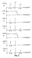
- Fig. 2a shows a frequency spectrum of the output signal of the frequency modulation circuit 2.
- the frequency of the carrier wave to be represented by J0
- the frequency of the first lower sideband component to be represented by J ⁇ 1
- the frequency of the first upper sideband component to be fc.fp. That is to say, assume that the frequency of the inputted video signal is fp.
- the first sideband components are illustrated but the following explanation can be applied to the case that the higher sideband components are considered.
- the filter circuit 3 is a low-pass filter having a frequency characteristic shown in Fig.2b.
- Fig. 2c shows a frequency spectrum of the output signal of the filter circuit 3.
- Fig. 2d shows a frequency spectrum of the FM signal recorded and reproduced through the tape-head system, i.e., the output signal of the reproducing amplifier 14, indicative of the level increase in the lower sideband. Further, as shown in Fig. 2d, an upper sideband component has been generated.
- the filter circuit 16 is a low-pass filter having a frequency characteristic of Fig. 2e.
- Fig. 2f shows a frequency spectrum of the FM signal after passed through the RF equalizer circuit 15 and the filter circuit 16. It is seen that the upper sideband component, which has a small S/N ratio, is attenuated.
- the equalizer circuit 15 may be a cosine equalizer.
- Fig. 2g shows a frequency spectrum of the output signal of the frequency demodulation circuit 17 which has a limiter circuit in the same way as the ordinary frequency demodulator. By passing through the limiter circuit, the upper sideband component is recovered.
- Fig. 2 d, f and g the levels of conventional frequency spectrum are shown by the mark X , and the levels of the frequency spectrum in the present invention by the mark ⁇ .
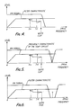
- Fig. 3 shows the examples of the variation rates of the lower sideband component level in Fig. 2d in the case of recording with attenuation of the upper sideband component of FM signal (mark ⁇ and solid line) and the case of recording without such attenuation (mark X and broken line), representing that the amount of level increase in the lower sideband is larger for the case of recording with attenuation of the upper sideband component.
- ⁇ 1 is defined as:
- the amount of level increase in the lower sideband becomes 3 ⁇ 4 dB larger in the case where the upper sideband component is attenuated in recording than in the case where the upper sideband component is not attenuated.
- the carrier wave component is not affected.
- the filter circuit 3 may be a trap circuit having a frequency characteristic as shown in Fig. 5 or a band elimination filter having a frequency characteristic as shown in Fig. 6.
- the mark ⁇ and the broken line show an upper sideband component.
- the trap circuit having the characteristic of Fig. 5 and the band elimination filter having the characteristic of Fig. 6 may be those which attenuate a component of the highest level out of the upper sideband components having the higher frequency than the white clip frequency.
Landscapes
- Engineering & Computer Science (AREA)
- Multimedia (AREA)
- Signal Processing (AREA)
- Television Signal Processing For Recording (AREA)
Applications Claiming Priority (2)
| Application Number | Priority Date | Filing Date | Title |
|---|---|---|---|
| JP248707/87 | 1987-10-01 | ||
| JP62248707A JPH0191304A (ja) | 1987-10-01 | 1987-10-01 | 磁気記録再生装置 |
Publications (2)
| Publication Number | Publication Date |
|---|---|
| EP0310418A2 true EP0310418A2 (fr) | 1989-04-05 |
| EP0310418A3 EP0310418A3 (fr) | 1991-09-18 |
Family
ID=17182139
Family Applications (1)
| Application Number | Title | Priority Date | Filing Date |
|---|---|---|---|
| EP19880309104 Withdrawn EP0310418A3 (fr) | 1987-10-01 | 1988-09-30 | Appareil magnétique d'enregistrement et de reproduction |
Country Status (4)
| Country | Link |
|---|---|
| US (1) | US4979046A (fr) |
| EP (1) | EP0310418A3 (fr) |
| JP (1) | JPH0191304A (fr) |
| KR (1) | KR910009020B1 (fr) |
Families Citing this family (5)
| Publication number | Priority date | Publication date | Assignee | Title |
|---|---|---|---|---|
| JP2507843B2 (ja) * | 1990-11-05 | 1996-06-19 | 三菱電機株式会社 | 映像信号再生装置及び時間軸補正装置 |
| KR940004499B1 (ko) * | 1991-12-23 | 1994-05-25 | 금성일렉트론 주식회사 | 브이 씨 알의 종단 기록 및 검출 회로 |
| US5355227A (en) * | 1992-02-07 | 1994-10-11 | Samsung Electronics Co., Ltd. | Linear-phase filtering for playback of recorded folded-spectrum video |
| KR0180211B1 (ko) * | 1996-02-26 | 1999-03-20 | 김두년 | 전열온수관의 난방방법 및 그장치 |
| JP2003123391A (ja) * | 2001-10-10 | 2003-04-25 | Hitachi Ltd | 情報記録再生装置用信号処理装置及び信号処理方法 |
Citations (2)
| Publication number | Priority date | Publication date | Assignee | Title |
|---|---|---|---|---|
| US4077046A (en) * | 1974-11-09 | 1978-02-28 | Sony Corporation | System for recording and/or reproducing a video signal |
| US4223282A (en) * | 1978-05-16 | 1980-09-16 | U.S. Philips Corporation | Method of reducing interference components in a frequency modulated signal and device for carrying out said method |
Family Cites Families (4)
| Publication number | Priority date | Publication date | Assignee | Title |
|---|---|---|---|---|
| FR1433418A (fr) * | 1965-02-10 | 1966-04-01 | Thomson Houston Comp Francaise | Perfectionnements aux procédés de transmission de signaux de télévision en couleur |
| JPS4944404B1 (fr) * | 1970-01-21 | 1974-11-28 | ||
| JPS61212984A (ja) * | 1985-03-18 | 1986-09-20 | Victor Co Of Japan Ltd | 磁気記録装置 |
| JPH0673163B2 (ja) * | 1986-07-22 | 1994-09-14 | 日本ビクター株式会社 | 映像信号記録装置 |
-
1987
- 1987-10-01 JP JP62248707A patent/JPH0191304A/ja active Pending
-
1988
- 1988-09-30 KR KR1019880012836A patent/KR910009020B1/ko not_active IP Right Cessation
- 1988-09-30 EP EP19880309104 patent/EP0310418A3/fr not_active Withdrawn
- 1988-10-03 US US07/253,218 patent/US4979046A/en not_active Expired - Lifetime
Patent Citations (2)
| Publication number | Priority date | Publication date | Assignee | Title |
|---|---|---|---|---|
| US4077046A (en) * | 1974-11-09 | 1978-02-28 | Sony Corporation | System for recording and/or reproducing a video signal |
| US4223282A (en) * | 1978-05-16 | 1980-09-16 | U.S. Philips Corporation | Method of reducing interference components in a frequency modulated signal and device for carrying out said method |
Non-Patent Citations (1)
| Title |
|---|
| GRUNDIG TECHN. INFORMATIONEN, vol. 25, no. 5, 1978, pages 293-299; W. W]RL: "Ein neuer professioneller Videorecorder aus der GPR-Familie für hochzeilige Fernsehaufzeichnung mit erhöhter Bandbreite" * |
Also Published As
| Publication number | Publication date |
|---|---|
| JPH0191304A (ja) | 1989-04-11 |
| KR890007252A (ko) | 1989-06-19 |
| US4979046A (en) | 1990-12-18 |
| EP0310418A3 (fr) | 1991-09-18 |
| KR910009020B1 (ko) | 1991-10-28 |
Similar Documents
| Publication | Publication Date | Title |
|---|---|---|
| EP0103287B1 (fr) | Dispositif d'enregistrement et de reproduction pour un enregistreur vidéo à bande magnétique | |
| EP0183186B1 (fr) | Appareil pour l'enregistrement et la reproduction de vidéosignaux et de signaux numériques autres que vidéo | |
| EP0038670A1 (fr) | Appareil vidéo d'enregistrement et de reproduction | |
| US4979046A (en) | Magnetic recording and reproducing apparatus for recording upper-sidebond-eliminated FM signal | |
| EP0334661A2 (fr) | Dispositif d'enregistrement et de reproduction magnétique | |
| US5220427A (en) | Magnetic reproducing apparatus having circuit for preventing reversal of white peak | |
| EP0086496B1 (fr) | Appareil magnétique d'enregistrement et de reproduction | |
| JPS6123715B2 (fr) | ||
| US4691246A (en) | Apparatus for multiplex recording and reproduction of audio and video signals | |
| EP0177235B1 (fr) | Appareil d'enregistrement de signaux de son et d'image | |
| US4928166A (en) | Apparatus for suppressing noises in a video signal | |
| EP0373074B1 (fr) | Circuit démodulateur de fréquence pour appareil de reproduction vidéo | |
| JPS6214906B2 (fr) | ||
| US4477837A (en) | Video signal recording-reproducing apparatus | |
| JPS6120068B2 (fr) | ||
| EP0170032A1 (fr) | Appareil d'enregistrement et de reproduction magnétique | |
| US5231542A (en) | Method and device for improving bass response in magnetic tape recording | |
| US4334249A (en) | Apparatus for use in recording a pulse signal on a magnetic recording medium | |
| JP2535263B2 (ja) | ディエンファシス回路 | |
| JPS5880990A (ja) | カラーテレビジョン信号の記録再生方法 | |
| KR0122765Y1 (ko) | 비데오 신호 처리 장치 | |
| JPH0256704A (ja) | 磁気記録再生装置 | |
| JPS5836876B2 (ja) | Secam方式カラ−映像信号記録再生方式 | |
| JPS62122491A (ja) | 映像信号記録再生装置 | |
| JPH02166667A (ja) | 記録再生方法 |
Legal Events
| Date | Code | Title | Description |
|---|---|---|---|
| PUAI | Public reference made under article 153(3) epc to a published international application that has entered the european phase |
Free format text: ORIGINAL CODE: 0009012 |
|
| AK | Designated contracting states |
Kind code of ref document: A2 Designated state(s): DE FR GB |
|
| PUAL | Search report despatched |
Free format text: ORIGINAL CODE: 0009013 |
|
| AK | Designated contracting states |
Kind code of ref document: A3 Designated state(s): DE FR GB |
|
| 17P | Request for examination filed |
Effective date: 19920317 |
|
| 17Q | First examination report despatched |
Effective date: 19931110 |
|
| STAA | Information on the status of an ep patent application or granted ep patent |
Free format text: STATUS: THE APPLICATION IS DEEMED TO BE WITHDRAWN |
|
| 18D | Application deemed to be withdrawn |
Effective date: 19940322 |