EP0310035B1 - Stator für einen bürstenlosen Motor - Google Patents
Stator für einen bürstenlosen Motor Download PDFInfo
- Publication number
- EP0310035B1 EP0310035B1 EP88115999A EP88115999A EP0310035B1 EP 0310035 B1 EP0310035 B1 EP 0310035B1 EP 88115999 A EP88115999 A EP 88115999A EP 88115999 A EP88115999 A EP 88115999A EP 0310035 B1 EP0310035 B1 EP 0310035B1
- Authority
- EP
- European Patent Office
- Prior art keywords
- stator
- printed substrate
- stator according
- yoke
- drive
- Prior art date
- Legal status (The legal status is an assumption and is not a legal conclusion. Google has not performed a legal analysis and makes no representation as to the accuracy of the status listed.)
- Expired - Lifetime
Links
Images

Classifications
-
- H—ELECTRICITY
- H02—GENERATION; CONVERSION OR DISTRIBUTION OF ELECTRIC POWER
- H02K—DYNAMO-ELECTRIC MACHINES
- H02K29/00—Motors or generators having non-mechanical commutating devices, e.g. discharge tubes or semiconductor devices
- H02K29/06—Motors or generators having non-mechanical commutating devices, e.g. discharge tubes or semiconductor devices with position sensing devices
- H02K29/08—Motors or generators having non-mechanical commutating devices, e.g. discharge tubes or semiconductor devices with position sensing devices using magnetic effect devices, e.g. Hall-plates, magneto-resistors
-
- Y—GENERAL TAGGING OF NEW TECHNOLOGICAL DEVELOPMENTS; GENERAL TAGGING OF CROSS-SECTIONAL TECHNOLOGIES SPANNING OVER SEVERAL SECTIONS OF THE IPC; TECHNICAL SUBJECTS COVERED BY FORMER USPC CROSS-REFERENCE ART COLLECTIONS [XRACs] AND DIGESTS
- Y10—TECHNICAL SUBJECTS COVERED BY FORMER USPC
- Y10S—TECHNICAL SUBJECTS COVERED BY FORMER USPC CROSS-REFERENCE ART COLLECTIONS [XRACs] AND DIGESTS
- Y10S310/00—Electrical generator or motor structure
- Y10S310/03—Hall effect generators and converters
-
- Y—GENERAL TAGGING OF NEW TECHNOLOGICAL DEVELOPMENTS; GENERAL TAGGING OF CROSS-SECTIONAL TECHNOLOGIES SPANNING OVER SEVERAL SECTIONS OF THE IPC; TECHNICAL SUBJECTS COVERED BY FORMER USPC CROSS-REFERENCE ART COLLECTIONS [XRACs] AND DIGESTS
- Y10—TECHNICAL SUBJECTS COVERED BY FORMER USPC
- Y10S—TECHNICAL SUBJECTS COVERED BY FORMER USPC CROSS-REFERENCE ART COLLECTIONS [XRACs] AND DIGESTS
- Y10S310/00—Electrical generator or motor structure
- Y10S310/06—Printed-circuit motors and components
Definitions
- the present invention relates generally to a stator for use in a brushless motor having a rotor, comprising: a stator yoke; a first printed substrate fixedly mounted on a first surface of said yoke; means for driving said brushless motor; a second printed substrate on which said motor driving means is mounted, said second printed substrate being fixedly mounted on a second surface of said yoke; a plurality of drive coils mounted on said first printed substrate and electrically connected thereto; and means for detecting a rotational position of said rotor.
- a stator is known from EP-A-0 210 835.
- US-A-4 435 673 discloses another brushless motor.
- Fig. 1A is a front view of a conventional stator
- Fig. 1B is a side view
- Fig. 1C is a rear view of the stator.
- the conventional stator is provided with a stator yoke 1, a first printed substrate 2 which is fixedly mounted on a front surface of the stator yoke 1 in such a manner that the substrate 2 faces a rotor of the motor, and a second printed substrate 3 which is fixedly mounted on a rear surface of the stator yoke 1.
- a plurality of drive coils 4 for rotating the rotor of the motor and a plurality of hall elements 5 for detecting a rotational position of the rotor are mounted on the first printed substrate 2 and electrically connected thereto.
- a group of drive circuits 6 is disposed on the second printed substrate 3 and electrically connected thereto.
- Figs. 1A, 1B and 1C six drive coils 4 and three hall elements 5 are utilized thereby constituting a three-phase drive system.
- the first printed substrate 2 and second printed substrate 3 are electrically connected to and communicated with each other through a plurality of copper wires 7.
- the copper wires 7 are insulated by a film 8 at an edge portion of the stator. Both ends of each of the drive coils 4 are connected to respective land portions 9 of the first printed substrate 2.
- the conventional stator thus constructed necessitates eleven copper wires 7 in total because three wires are required for the drive coils 4 and eight wires are required for the hall elements 8. These eleven wires 7 are gathered in one portion on the stator thereby raising a problem in that a large range is necessary to be provided both on the first and second printed substrates 2 and 3, so that the size of the stator would be disadvantageously increased.
- soldering steps are required for assembling the stator, for example, soldering steps for connecting the land portion 9 to a pattern of the first printed substrate 2, for connecting the pattern of the first printed substrate 2 to the copper wires 7, and for connecting the copper wires 7 to a pattern of the second printed substrate 3.
- An object of the invention is to provide a stator for use in a brushless motor in which copper wires are decreased in number and, therefore, soldering steps are decreased during the assembly process and, further, the stator can be made compact.
- the stator initially defined is characterized in that at least one of said printed substrates is provided with at least one notch through which an end of a respective one of the drive coils passes whereby said end is directly connected to said motor driving means.
- a stator which has a stator yoke, a first and second printed substrates, a plurality of drive coils and hall elements rounded on the first substrate, and a group of drive circuits mounted on the second substrate, wherein an end of the drive coil which is to be connected to the group of the drive circuits is connected to the second printed substrate directly and not through copper wires.
- the hall elements are positioned in a group of drive circuits. Such an arrangement is advantageous in that the copper wires can completely be eliminated and, further, the hall element does not interfere the drive coils so that the yield rate can be improved.
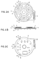
- Figs. 2A, 2B and 2C show a stator of a brushless motor according to a first embodiment of the present invention. More specifically, Fig. 2A shows a front surface of a stator. Fig. 2B is a side view of the stator and Fig. 2C shows a rear surface of the stator.
- the stator is provided with a stator yoke 11, a first printed substrate 12, and a second printed substrate 13.
- the first printed substrate 12 is fixedly mounted on a front surface of the stator yoke 11 which surface faces a rotor of the brushless motor (not shown).
- a plurality of drive coils 4 and a plurality of hall elements 5 are mounted on the first printed substrate 12 and electrically connected thereto.
- the second printed substrate 13 is fixedly mounted on a rear surface of the stator yoke 11.
- a group of the drive circuits 6 is disposed on the second printed substrate 13 and electrically connected thereto.
- the stator yoke 11 is made smaller in diameter than the first and second printed substrates 12 and 13. By this arrangement, a part 14 of the drive coils 4 does not contact the stator yoke 11 thereby being insulated therefrom. Therefore, the part 14 of the drive coils 4 is not necessary to be subjected to an extra insulating treatment. However, in case that either the stator yoke 11 or the part 14 of the drive coils 4 is subjected with an insulating treatment, the stator yoke 11 is not necessarily to be made smaller.
- Notches 15 and 16 are formed on an outer periphery both of the first printed substrate 12 and the second printed substrate 13 so that the part 14 of the drive coils 4 does not protrude from the outer periphery of the first and second printed substrates 12 and 13. Such an arrangement would decrease a possibility that the part 14 of the drive coils 4 may be broken during the assembly process of the stator. Further, since a position of the part 14 of the drive coil 4 can be fixed with respect both to the first and second substrates 12 and 13, the stator can be assembled with high efficiency.
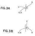
- the notches 15 and 16 are semicircular shaped. However, the notches may be V-shaped or Y-shaped as shown in Figs. 3A and 3B, respectively. These arrangements of the notches 15 and 16 are advantageous in that the efficiency of the assembly of the stator is further improved because the fixed position of the part 14 of the drive coil 4 is defined more accurately. Further, the notches 15 and 16 may be formed at an inner peripheral portion of the first and second printed substrates 12 and 13, respectively.
- a land portion 18 is formed on the second printed substrate 13 mounting the drive circuits at a surrounding of the notch 16, which land portion is connected to an end 17 of the drive coil 4 so that the end 17 is directly connected to the drive circuits mounted on the second substrate 13.
- Such a structure advantageously decreases the connection in number between the land portion 18 and the end 17 of the drive coil 4 to be connected to the drive circuits. Further, soldering steps during the assembly for soldering the end 17 of the drive coil 4 relative to the conventional structure can be decreased.
- first and second printed substrates 12 and 13 can be made smaller in size due to the decrease of the range for disposing the copper wires 7.
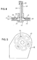
- Figs. 4 and 5 show a stator assembled in a brushless motor according to a second embodiment of the present invention. More specifically, Fig. 4 is a cross sectional view showing a stator which is actually assembled in a brushless motor and Fig. 5 shows a rear surface of the stator.
- the brushless motor is provided with a drive magnet 21 which is polarized alternately by S and N in the circumference direction thereof, a magnet yoke 22 mounting thereon the drive magnet 21, and a pulley 27 coupling thereto the magnet yoke 22.
- the pulley 27 is firmly fitted to a rotational shaft 28 which is rotatable with respect to a housing 30 through a bearing 29, so that the magnet 21, the magnet yoke 22 and the pulley 27 act as a rotor of the motor.
- the motor is further provided with a stator yoke 24, a first printed substrate 23 mounted on a front surface of the stator yoke 24, which front surface faces the rotor, and a second printed substrate 31 mounted on a rear surface of the stator yoke 24.
- the stator yoke 24, the first printed substrate 23 and the second printed substrate 31 are fixedly mounted on the housing 30 so that they act as a stator of the motor.
- a plurality of drive coils 25 are mounted on the first printed substrate 23 and electrically connected thereto, and a plurality of hall elements 26 for detecting a rotational position of the rotor of the motor are mounted on the second printed substrate 31.
- the stator yoke 24 is provided with through holes 32 on a position corresponding to the respective hall elements 26 mounted on the second printed substrate. The magnetic flux of the magnet 21 is applied to the hall elements 26 through the respective through holes 32.
- Fig. 5 shows a rear surface of the stator viewing from the upper side of the rotational shaft 28. Although it is not illustrated in Fig. 5, the through hole 32 is positioned under each of the hall elements 26.
- a group of drive circuits for driving the motor can be mounted on the second printed substrate 31. This provision eliminates whole copper wires for connecting the two printed substrates, so that the motor can be advantageously made compact in size.
- the hall elements are mounted on the second printed substrate 31.
- the hall elements may be buried into the second printed substrate.
- the magnetic flux to the hall elements can be increased thereby improving a detecting sensitivity of the rotational position of the rotor.
- an end of the drive coil to be connected to the drive circuits side is directly connected to a printed substrate mounting thereon drive circuits. Therefore, copper wires connecting a first printed substrate mounting drive coils to a second printed substrate mounting thereon the drive circuits can be effectively decreased.
- both of the printed substrates can be made compact and, further, soldering steps are advantageously decreased.
- hall elements are mounted directly on the second printed substrate. Under such a structure, a range of a land portion can be increased, a difficulty that an end terminal and a terminal of the hall elements may be short-circuited can be eliminated, and a shape and a winding number of the drive coil can be freely arranged. Accordingly, the yield rate is improved and, further, the motor can be made compact in size.
Claims (14)
- Stator zur Verwendung in einem bürstenlosen Motor mit einem Rotor, aufweisend:- ein Statorjoch (11, 24);- ein erstes gedrucktes Substrat (12, 23), das fest auf einer ersten Oberfläche des Joches montiert ist;- Einrichtungen (6) zum Antreiben des bürstenlosen Motors;- ein zweites gedrucktes Substrat (13, 31), auf dem die Motorantriebseinrichtung montiert ist, wobei das zweite gedruckte Substrat (13, 31) fest auf einer zweiten Oberfläche des Joches (11, 24) montiert ist;- eine Vielzahl von Antriebswicklungen (4, 25), die auf dem ersten gedruckten Substrat (12, 23) montiert und elektrisch daran angeschlossen sind; und- Einrichtungen (5) zum Erfassen der Umdrehungsstellung des Rotors,dadurch gekennzeichnet, daß mindestens eines der gedruckten Substrate mit mindestens einer Kerbe (15, 16) versehen ist, durch die ein Ende (17) einer entsprechenden Wicklung der Antriebswicklungen (4, 25) hindurchtritt, wodurch das Ende (17) direkt an die Motorantriebseinrichtungen (6) angeschlossen wird.
- Stator nach Anspruch 1, bei dem die bzw. jede Kerbe (15) an einer äußeren Peripherie des ersten gedruckten Substrates (12, 23) angebracht ist.
- Stator nach Anspruch 1, bei dem die oder jede Kerbe (15) auf einer inneren Peripherie des ersten gedruckten Substrates (12, 23) angebracht ist.
- Stator nach einem beliebigen vorhergehenden Anspruch, bei dem die oder jede Kerbe (15, 16) halbkreisförmig ist.
- Stator nach einem beliebigen Anspruch 1 bis 3, bei dem die oder jede Kerbe (15, 16) V-förmig ist.
- Stator nach einem beliebigen Anspruch 1 bis 3, bei dem die oder jede Kerbe (15, 16) Y-förmig ist.
- Stator nach einem beliebigen vorhergehenden Anspruch, bei dem das Joch (11, 24) im Durchmesser kleiner als das erste gedruckte Substrat (12, 23) ist, wodurch das Ende jeder Antriebswicklung (4, 25) nicht das Statorjoch (11, 24) kontaktiert.
- Stator nach einem beliebigen vorhergehenden Anspruch, bei dem die Erfassungseinrichtung getrennt von den Antriebswicklungen (4, 25) angeordnet ist, die auf dem ersten gedruckten Substrat (12, 23) montiert sind.
- Stator nach einem beliebigen vorhergehenden Anspruch, bei dem die Erfassungseinrichtung auf dem zweiten gedruckten Substrat (13, 31) montiert ist.
- Stator nach Anspruch 9, bei dem das Statorjoch (11, 24) mit einem Durchgangsloch in einem Abschnitt versehen ist, der der Erfassungseinrichtung entspricht.
- Stator nach einem beliebigen Anspruch 1 bis 8, bei dem die Erfassungseinrichtung im zweiten gedruckten Substrat (13, 31) vergraben ist.
- Stator nach einem beliebigen vorhergehenden Anspruch, bei dem die Erfassungseinrichtung eine Vielzahl von Hall-Elementen (5, 26) umfaßt.
- Stator nach Anspruch 12, bei dem sechs der Antriebswicklungen (4, 25) und drei der Hall-Elemente (5, 26) vorgesehen sind, wodurch ein Dreiphasenantriebssystem gebildet wird.
- Stator nach einem beliebigen vorhergehenden Anspruch, bei dem das zweite gedruckte Substrat (13, 31) Kontaktabschnitte (18) für den Anschluß an entsprechende Enden (17) der Antriebswicklungen (4, 25) trägt.
Applications Claiming Priority (4)
| Application Number | Priority Date | Filing Date | Title |
|---|---|---|---|
| JP62240794A JPH084382B2 (ja) | 1987-09-28 | 1987-09-28 | ブラシレスモータ |
| JP240794/87 | 1987-09-28 | ||
| JP62251722A JPH084381B2 (ja) | 1987-10-07 | 1987-10-07 | ブラシレスモータのステータ |
| JP251722/87 | 1987-10-07 |
Publications (3)
| Publication Number | Publication Date |
|---|---|
| EP0310035A2 EP0310035A2 (de) | 1989-04-05 |
| EP0310035A3 EP0310035A3 (en) | 1989-10-18 |
| EP0310035B1 true EP0310035B1 (de) | 1994-07-27 |
Family
ID=26534931
Family Applications (1)
| Application Number | Title | Priority Date | Filing Date |
|---|---|---|---|
| EP88115999A Expired - Lifetime EP0310035B1 (de) | 1987-09-28 | 1988-09-28 | Stator für einen bürstenlosen Motor |
Country Status (3)
| Country | Link |
|---|---|
| US (1) | US4961017A (de) |
| EP (1) | EP0310035B1 (de) |
| DE (1) | DE3850836T2 (de) |
Families Citing this family (28)
| Publication number | Priority date | Publication date | Assignee | Title |
|---|---|---|---|---|
| CH669059A5 (de) * | 1985-07-24 | 1989-02-15 | Papst Motoren Gmbh & Co Kg | Antriebssystem fuer kassettierte signalbaender. |
| US5291104A (en) * | 1989-02-08 | 1994-03-01 | Matsushita Electric Industrial Co., Ltd. | DC commutatorless motor |
| DE9012087U1 (de) * | 1990-08-22 | 1992-01-02 | Papst-Motoren Gmbh & Co Kg, 7742 St Georgen, De | |
| US6204996B1 (en) * | 1992-10-16 | 2001-03-20 | Seagate Technology Llc | Low profile spindle motor |
| JPH0775303A (ja) * | 1993-07-09 | 1995-03-17 | Tamron Co Ltd | アクチュエータ装置及びアクチュエータ |
| JP2854519B2 (ja) * | 1994-02-07 | 1999-02-03 | 株式会社三協精機製作所 | ブラシレスモータ |
| JPH0833300A (ja) * | 1994-07-14 | 1996-02-02 | Matsushita Electric Ind Co Ltd | ブラシレスモータ |
| JP3524179B2 (ja) * | 1994-11-17 | 2004-05-10 | キヤノン株式会社 | キャプスタンモータ |
| JP3768571B2 (ja) * | 1995-10-06 | 2006-04-19 | 日本電産株式会社 | スピンドルモータ |
| US5945766A (en) * | 1996-01-18 | 1999-08-31 | Amotron Co., Ltd. | Coreless-type BLDC motor and method of producing stator assembly having axial vibration attenuation arrangement |
| US5895994A (en) * | 1997-01-30 | 1999-04-20 | General Electric Company | Dynamoelectric machine |
| DE19817333C5 (de) * | 1998-04-18 | 2007-04-26 | Conti Temic Microelectronic Gmbh | Elektrische Antriebseinheit aus Elektromotor und Elektronikmodul |
| US6104113A (en) * | 1998-05-14 | 2000-08-15 | General Electric Company | Coil assembly for sensorless rotor angular position control of single phase permanent magnet motor |
| EP1219005A4 (de) * | 1999-09-16 | 2012-01-25 | Gm Global Tech Operations Inc | Tachometer und verfahren zur messung der motorgeschwindigkeit |
| US6530269B1 (en) | 1999-09-16 | 2003-03-11 | Delphi Technologies, Inc. | Enhanced motor velocity measurement using a blend of fixed period and fixed distance techniques |
| US6510396B1 (en) | 1999-09-16 | 2003-01-21 | Delphi Technologies, Inc. | Symmetry compensation for encoder pulse width variation |
| CN1520632A (zh) * | 2001-06-26 | 2004-08-11 | �Ƚ�ת��ϵͳ���Ϲ�˾ | 无刷直流电动机 |
| DE60237974D1 (de) * | 2001-07-27 | 2010-11-25 | Delphi Tech Inc | Tachometervorrichtung und verfahren zur motorgeschwindigkeitsmessung |
| KR200268109Y1 (ko) * | 2001-12-06 | 2002-03-15 | 김정훈 | 편평형 무정류자 진동모터 |
| US20040061390A1 (en) * | 2002-10-01 | 2004-04-01 | Baker-Bachman Shawn Lawrence | Apparatus and method for connecting parallel stator windings |
| WO2004047252A1 (ja) * | 2002-11-18 | 2004-06-03 | Seiko Epson Corporation | ブラシレスモータのステータ、及び、これを備えたブラシレスモータ、並びにコイル構造 |
| US20060055265A1 (en) * | 2004-09-16 | 2006-03-16 | Zalusky James T | Printed circuit board motor |
| US20100308684A1 (en) * | 2008-01-18 | 2010-12-09 | Alex Horng | Motor with Detacthable Winding Assemblies |
| US9257876B2 (en) * | 2008-11-14 | 2016-02-09 | Metal Industries Research & Development Centre | Motor integrated to electronic device |
| US8193678B2 (en) * | 2009-09-07 | 2012-06-05 | Sunonwealth Electric Machine Industry Co., Ltd. | Coil unit for motor stator |
| US8872401B2 (en) * | 2012-10-05 | 2014-10-28 | Asia Vital Components (China) Co., Ltd. | Securing structure for fan sensing element |
| CN104716766A (zh) * | 2013-12-13 | 2015-06-17 | 博立码杰通讯(深圳)有限公司 | 电磁电机 |
| US10340760B2 (en) * | 2017-01-11 | 2019-07-02 | Infinitum Electric Inc. | System and apparatus for segmented axial field rotary energy device |
Family Cites Families (13)
| Publication number | Priority date | Publication date | Assignee | Title |
|---|---|---|---|---|
| JPS5229904A (en) * | 1975-09-03 | 1977-03-07 | Hitachi Ltd | Stator for electromagnetic machine |
| US4039875A (en) * | 1975-11-07 | 1977-08-02 | Computer Devices Corporation | Method and apparatus for interconnecting stator coils |
| US4224543A (en) * | 1978-08-01 | 1980-09-23 | Rapidsyn Co. | Printed circuit terminal for interconnecting stator coils |
| JPS576591A (en) * | 1980-06-11 | 1982-01-13 | Japan Servo Co Ltd | Direct current brushless motor and drive controller thereof |
| JPS5886852A (ja) * | 1981-11-14 | 1983-05-24 | Hitachi Ltd | 平面対向型モ−タの固定子 |
| US4594524A (en) * | 1984-02-22 | 1986-06-10 | Kangyo Denkikiki Kabushiki Kaisha | Coreless-brushless motor |
| US4668884A (en) * | 1984-04-27 | 1987-05-26 | Sanyo Electric Co | Brushless motor |
| JPS6184683U (de) * | 1984-11-07 | 1986-06-04 | ||
| DE3526166C2 (de) * | 1984-07-23 | 1996-05-02 | Asahi Chemical Ind | Bürstenloser Elektromotor und Verfahren zum Herstellen einer Spuleneinheit für diesen |
| JPS6141382U (ja) * | 1984-08-17 | 1986-03-15 | アルプス電気株式会社 | ブラシレスモータ |
| DE3687932T2 (de) * | 1985-07-23 | 1993-09-30 | Kanegafuchi Chemical Ind | Laser-Abtastmotor und seine Herstellung. |
| DE3672560D1 (de) * | 1985-09-23 | 1990-08-16 | Siemens Ag | Elektromotor, insbesondere dauermagneterregter aussenlaeufermotor. |
| JPS62135574U (de) * | 1986-02-19 | 1987-08-26 |
-
1988
- 1988-09-26 US US07/248,826 patent/US4961017A/en not_active Expired - Fee Related
- 1988-09-28 DE DE3850836T patent/DE3850836T2/de not_active Expired - Fee Related
- 1988-09-28 EP EP88115999A patent/EP0310035B1/de not_active Expired - Lifetime
Non-Patent Citations (1)
| Title |
|---|
| PATENT ABSTRACTS OF JAPAN, vol. 7, no. 182 (E-192)(1327), 11th August 1983; & JP-A-58 86852 * |
Also Published As
| Publication number | Publication date |
|---|---|
| DE3850836T2 (de) | 1994-12-22 |
| US4961017A (en) | 1990-10-02 |
| DE3850836D1 (de) | 1994-09-01 |
| EP0310035A2 (de) | 1989-04-05 |
| EP0310035A3 (en) | 1989-10-18 |
Similar Documents
| Publication | Publication Date | Title |
|---|---|---|
| EP0310035B1 (de) | Stator für einen bürstenlosen Motor | |
| US5637945A (en) | Brushless motor | |
| US7373711B2 (en) | Motor armature manufacturing method | |
| US6600244B2 (en) | Electric motor | |
| EP0161032B1 (de) | Elektrischer Motor | |
| EP1522133A1 (de) | Verbindungsring und drahtführung für einen stator einer elektrischen maschine | |
| US6181046B1 (en) | Dynamo-electric machine with commutator assembly | |
| US5493159A (en) | Flex circuit for electric motor | |
| KR100567482B1 (ko) | 브러시리스 모터 | |
| US5268604A (en) | Armature of a small motor employing an insulating holder having a plurality of sections | |
| US5949174A (en) | Commutator for two speed electric motor and motor incorporating same | |
| JPS61231859A (ja) | Dcモータ | |
| US4341973A (en) | Armature in electrical rotary machine | |
| JPH0218692Y2 (de) | ||
| KR100278894B1 (ko) | 소형 모터 | |
| EP0441376B1 (de) | Frequenzgenerator | |
| JPH0614773B2 (ja) | ブラシレスモ−タ | |
| JPS6137862B2 (de) | ||
| JP3376327B2 (ja) | スピンドルモータ | |
| JPH084381B2 (ja) | ブラシレスモータのステータ | |
| JP2551168Y2 (ja) | ディスク駆動用モータ | |
| JP3174517B2 (ja) | 扁平モータ | |
| JPH1094206A (ja) | スピンドルモータ | |
| JP2556936Y2 (ja) | ステッピングモータ | |
| JP2586955Y2 (ja) | 小型モータの端子構造 |
Legal Events
| Date | Code | Title | Description |
|---|---|---|---|
| PUAI | Public reference made under article 153(3) epc to a published international application that has entered the european phase |
Free format text: ORIGINAL CODE: 0009012 |
|
| AK | Designated contracting states |
Kind code of ref document: A2 Designated state(s): DE FR GB NL |
|
| RAP1 | Party data changed (applicant data changed or rights of an application transferred) |
Owner name: AKAI ELECTRIC CO., LTD. |
|
| PUAL | Search report despatched |
Free format text: ORIGINAL CODE: 0009013 |
|
| AK | Designated contracting states |
Kind code of ref document: A3 Designated state(s): DE FR GB NL |
|
| 17P | Request for examination filed |
Effective date: 19900122 |
|
| 17Q | First examination report despatched |
Effective date: 19911004 |
|
| GRAA | (expected) grant |
Free format text: ORIGINAL CODE: 0009210 |
|
| AK | Designated contracting states |
Kind code of ref document: B1 Designated state(s): DE FR GB NL |
|
| REF | Corresponds to: |
Ref document number: 3850836 Country of ref document: DE Date of ref document: 19940901 |
|
| ET | Fr: translation filed | ||
| PLBE | No opposition filed within time limit |
Free format text: ORIGINAL CODE: 0009261 |
|
| STAA | Information on the status of an ep patent application or granted ep patent |
Free format text: STATUS: NO OPPOSITION FILED WITHIN TIME LIMIT |
|
| 26N | No opposition filed | ||
| PGFP | Annual fee paid to national office [announced via postgrant information from national office to epo] |
Ref country code: GB Payment date: 19990922 Year of fee payment: 12 |
|
| PGFP | Annual fee paid to national office [announced via postgrant information from national office to epo] |
Ref country code: NL Payment date: 19990930 Year of fee payment: 12 Ref country code: FR Payment date: 19990930 Year of fee payment: 12 |
|
| PGFP | Annual fee paid to national office [announced via postgrant information from national office to epo] |
Ref country code: DE Payment date: 19991019 Year of fee payment: 12 |
|
| PG25 | Lapsed in a contracting state [announced via postgrant information from national office to epo] |
Ref country code: GB Free format text: LAPSE BECAUSE OF NON-PAYMENT OF DUE FEES Effective date: 20000928 |
|
| PG25 | Lapsed in a contracting state [announced via postgrant information from national office to epo] |
Ref country code: NL Free format text: LAPSE BECAUSE OF NON-PAYMENT OF DUE FEES Effective date: 20010401 |
|
| GBPC | Gb: european patent ceased through non-payment of renewal fee |
Effective date: 20000928 |
|
| PG25 | Lapsed in a contracting state [announced via postgrant information from national office to epo] |
Ref country code: FR Free format text: LAPSE BECAUSE OF NON-PAYMENT OF DUE FEES Effective date: 20010531 |
|
| NLV4 | Nl: lapsed or anulled due to non-payment of the annual fee |
Effective date: 20010401 |
|
| PG25 | Lapsed in a contracting state [announced via postgrant information from national office to epo] |
Ref country code: DE Free format text: LAPSE BECAUSE OF NON-PAYMENT OF DUE FEES Effective date: 20010601 |
|
| REG | Reference to a national code |
Ref country code: FR Ref legal event code: ST |