EP0309662B1 - Oberschenkelteil einer Hüftgelenkendoprothese - Google Patents
Oberschenkelteil einer Hüftgelenkendoprothese Download PDFInfo
- Publication number
- EP0309662B1 EP0309662B1 EP88111212A EP88111212A EP0309662B1 EP 0309662 B1 EP0309662 B1 EP 0309662B1 EP 88111212 A EP88111212 A EP 88111212A EP 88111212 A EP88111212 A EP 88111212A EP 0309662 B1 EP0309662 B1 EP 0309662B1
- Authority
- EP
- European Patent Office
- Prior art keywords
- shaft
- openings
- bone
- hip joint
- femoral portion
- Prior art date
- Legal status (The legal status is an assumption and is not a legal conclusion. Google has not performed a legal analysis and makes no representation as to the accuracy of the status listed.)
- Expired - Lifetime
Links
- 210000004394 hip joint Anatomy 0.000 title claims abstract description 7
- 229910000531 Co alloy Inorganic materials 0.000 claims description 2
- RTAQQCXQSZGOHL-UHFFFAOYSA-N Titanium Chemical compound [Ti] RTAQQCXQSZGOHL-UHFFFAOYSA-N 0.000 claims description 2
- SZMZREIADCOWQA-UHFFFAOYSA-N chromium cobalt nickel Chemical compound [Cr].[Co].[Ni] SZMZREIADCOWQA-UHFFFAOYSA-N 0.000 claims description 2
- 238000005266 casting Methods 0.000 claims 1
- 239000011796 hollow space material Substances 0.000 claims 1
- 210000000988 bone and bone Anatomy 0.000 description 25
- 210000000689 upper leg Anatomy 0.000 description 12
- 239000000463 material Substances 0.000 description 7
- 239000002639 bone cement Substances 0.000 description 4
- 239000000126 substance Substances 0.000 description 3
- 230000015572 biosynthetic process Effects 0.000 description 2
- 230000000694 effects Effects 0.000 description 2
- 238000002513 implantation Methods 0.000 description 2
- 240000007124 Brassica oleracea Species 0.000 description 1
- 235000003899 Brassica oleracea var acephala Nutrition 0.000 description 1
- 235000011301 Brassica oleracea var capitata Nutrition 0.000 description 1
- 235000001169 Brassica oleracea var oleracea Nutrition 0.000 description 1
- 238000004873 anchoring Methods 0.000 description 1
- 239000004568 cement Substances 0.000 description 1
- 229910052588 hydroxylapatite Inorganic materials 0.000 description 1
- XYJRXVWERLGGKC-UHFFFAOYSA-D pentacalcium;hydroxide;triphosphate Chemical compound [OH-].[Ca+2].[Ca+2].[Ca+2].[Ca+2].[Ca+2].[O-]P([O-])([O-])=O.[O-]P([O-])([O-])=O.[O-]P([O-])([O-])=O XYJRXVWERLGGKC-UHFFFAOYSA-D 0.000 description 1
- 239000007787 solid Substances 0.000 description 1
- 230000003746 surface roughness Effects 0.000 description 1
- 239000010936 titanium Substances 0.000 description 1
- 229910052719 titanium Inorganic materials 0.000 description 1
- 230000003313 weakening effect Effects 0.000 description 1
Images
Classifications
-
- A—HUMAN NECESSITIES
- A61—MEDICAL OR VETERINARY SCIENCE; HYGIENE
- A61F—FILTERS IMPLANTABLE INTO BLOOD VESSELS; PROSTHESES; DEVICES PROVIDING PATENCY TO, OR PREVENTING COLLAPSING OF, TUBULAR STRUCTURES OF THE BODY, e.g. STENTS; ORTHOPAEDIC, NURSING OR CONTRACEPTIVE DEVICES; FOMENTATION; TREATMENT OR PROTECTION OF EYES OR EARS; BANDAGES, DRESSINGS OR ABSORBENT PADS; FIRST-AID KITS
- A61F2/00—Filters implantable into blood vessels; Prostheses, i.e. artificial substitutes or replacements for parts of the body; Appliances for connecting them with the body; Devices providing patency to, or preventing collapsing of, tubular structures of the body, e.g. stents
- A61F2/02—Prostheses implantable into the body
- A61F2/30—Joints
- A61F2/32—Joints for the hip
- A61F2/36—Femoral heads ; Femoral endoprostheses
- A61F2/3662—Femoral shafts
-
- A—HUMAN NECESSITIES
- A61—MEDICAL OR VETERINARY SCIENCE; HYGIENE
- A61F—FILTERS IMPLANTABLE INTO BLOOD VESSELS; PROSTHESES; DEVICES PROVIDING PATENCY TO, OR PREVENTING COLLAPSING OF, TUBULAR STRUCTURES OF THE BODY, e.g. STENTS; ORTHOPAEDIC, NURSING OR CONTRACEPTIVE DEVICES; FOMENTATION; TREATMENT OR PROTECTION OF EYES OR EARS; BANDAGES, DRESSINGS OR ABSORBENT PADS; FIRST-AID KITS
- A61F2/00—Filters implantable into blood vessels; Prostheses, i.e. artificial substitutes or replacements for parts of the body; Appliances for connecting them with the body; Devices providing patency to, or preventing collapsing of, tubular structures of the body, e.g. stents
- A61F2/02—Prostheses implantable into the body
- A61F2/30—Joints
- A61F2002/30001—Additional features of subject-matter classified in A61F2/28, A61F2/30 and subgroups thereof
- A61F2002/30316—The prosthesis having different structural features at different locations within the same prosthesis; Connections between prosthetic parts; Special structural features of bone or joint prostheses not otherwise provided for
- A61F2002/30535—Special structural features of bone or joint prostheses not otherwise provided for
-
- A—HUMAN NECESSITIES
- A61—MEDICAL OR VETERINARY SCIENCE; HYGIENE
- A61F—FILTERS IMPLANTABLE INTO BLOOD VESSELS; PROSTHESES; DEVICES PROVIDING PATENCY TO, OR PREVENTING COLLAPSING OF, TUBULAR STRUCTURES OF THE BODY, e.g. STENTS; ORTHOPAEDIC, NURSING OR CONTRACEPTIVE DEVICES; FOMENTATION; TREATMENT OR PROTECTION OF EYES OR EARS; BANDAGES, DRESSINGS OR ABSORBENT PADS; FIRST-AID KITS
- A61F2250/00—Special features of prostheses classified in groups A61F2/00 - A61F2/26 or A61F2/82 or A61F9/00 or A61F11/00 or subgroups thereof
- A61F2250/0058—Additional features; Implant or prostheses properties not otherwise provided for
Definitions
- the invention relates to a thigh part of a hip joint endoprosthesis according to the preamble of patent claim 1.
- the basic alternative is to anchor the shaft of the thigh part in the femoral canal with or without bone cement.
- bone cement enables a very intimate and firm connection between the shaft and the bone.
- micro-movements which can lead to the inoperative functioning of the endoprosthesis.
- a reoperation is then required. Thigh parts implanted with bone cement can only be surgically removed with considerable effort.
- a hip joint prosthesis with a perforated hollow shaft has become known from EP-A-0 065 481.
- the hollow shaft is made of flat material, which is bent into the desired cross-sectional shape and attached to the prosthesis neck using suitable precautions. Means are also provided to hold the abutting ends of the sheet together.
- the main goal of such a prosthesis is to adapt its elasticity behavior to the elasticity of the bone.
- the formation of openings in the prosthesis socket enables bone material to grow in and the bone to grow together with cancellous bone which is filled into the hollow socket.
- the invention has for its object to provide a cementless implantable hip joint endoprosthesis, the thigh part ensures the greatest possible connection between the thigh part and the bone with sufficient stability of the prosthesis. Furthermore, simple production should be possible.
- the shaft is shaped as a cast part of a chromium-nickel cobalt alloy or titanium. It can therefore be produced in a simple manner from body-compatible material.
- the hollow shaft of the thigh part according to the invention is provided with approximately parallel dorsal and ventral sides, while the medial and lateral sides are arcuate in cross section is rounded. This gives the shaft a high moment of inertia and thus sufficient stability, which is important for the hollow body.
- Conventional prostheses are usually provided with a solid shaft.
- the openings in connection with the interior of the shaft are only formed on the dorsal and ventral side.
- the medial and lateral sides, which are subjected to tension or pressure, are essentially responsible for the strength. A weakening through holes would be disadvantageous here.
- the attachment of the holes on the dorsal or ventral side affects the stability only slightly if the opening cross section is chosen to be relatively large.
- circular and elongated openings alternate with one another, thus ensuring the largest possible opening cross section for the effective ingrowth of bone material or spongiosa growing together in the shaft interior and bone outside the shaft.
- the same purpose serves the formation of a second row of openings in the proximal part of the shaft, which naturally has a larger diameter in relation to the rest of the area in the lateral medial plane.
- the thigh part according to the invention therefore secures one greatest possible connection between the bone materials inside and outside the shaft.
- the surgeon can fill the body's autologous and heterologous cancellous bone during the operation. It is also conceivable to fill in hydroxyapatite, a material used for artificial tooth roots.
- the cancellous bone located in the cabbage body of the shaft and the openings enables the prosthesis to heal in the femur through genuine bony connection, so that a secure anchoring is obtained which is also safe over a longer period of time.
- the design of the shaft and the arrangement of the openings ensure sufficient stability of the shaft.
- the width of the openings in the distal area of the shaft is greater than half, preferably two thirds, of the shaft dimension in the lateral / medial plane. This creates a large opening cross section, which is of great advantage for the desired bone connection of the bone materials.
- edges of the openings are rounded according to one embodiment of the invention.
- Another embodiment of the invention provides that the Openings in opposite sides face each other. This arrangement has the advantage that the openings can accommodate screws, for example for attaching a plate to the outside of the bone.
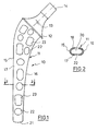
- FIG. 1 shows a thigh part 10. It consists of a relatively long, slim shaft 11, a collar 12 and a conically tapering neck 13 which at the end has a cone 14 for receiving a joint ball which has a corresponding, matching inner cone.
- the angle between the shaft and neck axis is 135 °.
- the shaft 11 has a lateral side 15 and a medial side 16. It is assumed that the other visible side 17 of the shaft is the front.
- the dorsal side is designated 18 (Fig. 2). It can be seen from FIG. 2 that the frontal and dorsal sides 17 and 18 run approximately parallel and that medial side 16 and lateral side 15 are curved in an arc. It is particularly important, however, that the shaft 11 has a cavity 20 which extends in a channel-like manner through the length of the entire shaft. The cavity 20 is open towards the distal end 21 of the shaft 11.
- the frontal side 17 of the shaft 11 is provided with a series of openings which extend from the distal to the proximal end of the shaft 11, circular openings 22 alternating with elongated openings 23.
- the openings 22 have a diameter which is greater than half the width of the shaft or the frontal side.
- the width of the openings 23 corresponds to the diameter of the openings 22.
- the length of the openings is approximately as large as twice the diameter of the openings 22.
- a second row of openings 22 and 23 is provided in the proximal region. It can be seen that a large proportion of the area of the frontal side 17 is perforated. It can be larger than the proportion of the unperforated area.
- the opposite rear side 18 of the shaft 11 is provided with holes in a corresponding manner as shown in FIG. 1, these preferably being offset from the holes on the side 17.
- the shaft 11 shown is hollow because it is to be filled with the body's own or heterologous cancellous bone or a similar substance which promotes ingrowth of the shaft.
- the holes or openings 22, 23 thus allow the cancellous bone in the shaft 11 to grow together with the cancellous bone in the bone canal or the remaining bone substance.
- the shaft 11 is shown and described as being hollow throughout. It goes without saying that it may also be sufficient under certain circumstances to only partially shape the shaft 11 in order to obtain the desired effects.
Landscapes
- Health & Medical Sciences (AREA)
- Orthopedic Medicine & Surgery (AREA)
- Vascular Medicine (AREA)
- Life Sciences & Earth Sciences (AREA)
- Transplantation (AREA)
- Engineering & Computer Science (AREA)
- Biomedical Technology (AREA)
- Heart & Thoracic Surgery (AREA)
- Cardiology (AREA)
- Oral & Maxillofacial Surgery (AREA)
- Animal Behavior & Ethology (AREA)
- General Health & Medical Sciences (AREA)
- Public Health (AREA)
- Veterinary Medicine (AREA)
- Prostheses (AREA)
- Materials For Medical Uses (AREA)
- Golf Clubs (AREA)
Description
- Die Erfindung bezieht sich auf ein Oberschenkelteil einer Hüftgelenkendoprothese nach dem Oberbegriff des Patentanspruchs 1.
- Beim Einsatz bekannter Endoprothesen für das Hüftgelenk besteht die grundsätzliche Alternative, den Schaft des Oberschenkelteils im Femurkanal mit oder ohne Knochenzement zu verankern. Die Verwendung von Knochenzement ermöglicht eine sehr innige und feste Verbindung zwischen dem Schaft und dem Knochen. Es besteht jedoch die Gefahr, daß durch sogenannte Mikrobewegungen eine Lockerung des Schaftes im Knochenzement eintritt, die bis zur Funktionsunfähigkeit der Endoprothese führen kann. Eine Reoperation ist dann erforderlich. Mit Knochenzement implantierte Oberschenkelteile lassen sich jedoch nur mit erheblicher Mühe operativ entfernen.
- Bei zementlosen Schäften wird versucht, einen Kraftschluß zwischen Schaft und Knochen zu erzeugen. Hierzu ist erforderlich, daß der Schaft mit beträchtlicher Spannung im Knochenkanal sitzt. Ein Entfernen eines derartigen Schaftes stellt sich einfacher dar als ein mit Zement implantierter Schaft. Ein zementloser Schaft stellt jedoch für den Knochen eine höhere Belastung dar, so daß es zu Beschädigungen des Knochens beim Implantieren kommen kann. Um eine innigere Verbindung zwischen einem zementlos implantierten Schaft und dem Knochen zu erhalten, ist auch bekannt, den Schaft mit Oberflächenrauhigkeiten, Vertiefungen oder dergleichen zu versehen oder seiner Oberfläche eine vorgegebene geometrische Struktur zu erteilen. Die Knochensubstanz soll nach der Implantation in die Vertiefungen und Unebenheiten hineinwachsen und dadurch die Fixierung des Schaftes bzw. die Lastübertragung verbessern.
- Aus der EP-A-0 065 481 ist eine Hüftgelenkprothese mit gelochtem Hohlschaft bekanntgeworden. Der Hohlschaft ist aus Flachmaterial gefertigt, das in die gewünschte Querschnittsform gebogen und mit Hilfe geeigneter Vorkehrungen am Prothesenhals befestigt wird. Ferner sind Mittel vorgesehen, um die aneinanderstoßenden Enden des Flachmaterials zusammenzuhalten. Hauptziel einer derartigen Prothese ist die Anpassung ihres Elastizitätsverhaltens an die Elastizität des Knochens. Ferner ermöglicht die Ausbildung von Öffnungen im Prothesenschaft das Einwachsen von Knochenmaterial sowie das Verwachsen des Knochens mit Spongiosa, die in den Hohlschaft eingefüllt wird.
- Der Erfindung liegt die Aufgabe zugrunde, eine zementfrei implantierbare Hüftgelenkendoprothese zu schaffen, deren Oberschenkelteil eine größtmögliche Verbindung zwischen dem Oberschenkelteil und dem Knochen gewährleistet bei ausreichender Stabilität der Prothese. Ferner soll eine einfache Herstellung möglich sein.
- Diese Aufgabe wird erfindungsgemäß durch die Merkmale des Kennzeichnungsteils des Patentanspruchs 1 gelöst.
- Beim erfindungsgemäßen Oberschenkelteil ist der Schaft als Gußteil einer Chromnickelkobaltlegierung oder Titan geformt. Sie läßt sich daher auf einfache Weise aus körperverträglichem Material herstellen. Der hohle Schaft des erfindungsgemäßen Oberschenkelteils ist mit annähernd parallelen dorsalen und ventralen Seiten versehen, während die mediale und die laterale Seite im Querschnitt bogenförmig gerundet ist. Dadurch erhält der Schaft ein hohes Trägheitsmoment und damit eine ausreichende Stabilität, was für die Hohlkörperausbildung von Bedeutung ist. Herkömmliche Prothesen sind normalerweise mit einem massiven Schaft versehen. Die mit dem Schaftinneren in Verbindung stehenden Öffnungen sind ausschließlich an der dorsalen und der ventralen Seite geformt. Für die Festigkeit ist im wesentlichen die mediale und die laterale Seite verantwortlich, die auf Zug bzw. Druck beansprucht werden. Hier wäre eine Schwächung durch Löcher nachteilig. Die Anbringung der Löcher an der dorsalen oder ventralen Seite beeinträchtigt die Stabilität auch dann nur geringfügig, wenn der Öffnungsquerschnitt verhältnismäßig groß gewählt wird.
- Bei dem erfindungsgemäßen Oberschenkelteil wechseln kreisrunde und längliche Öffnungen einander ab, gewährleisten mithin einen größtmöglichen Öffnungsquerschnitt zwecks wirksamen Einwachsens von Knochenmaterial bzw. Zusammenwachsens von Spongiosa im Schaftinneren und Knochen außerhalb des Schafts. Dem gleichen Zweck dient die Ausbildung einer zweiten Öffnungsreihe im proximalen Teil des Schaftes, der naturgemäß in der Lateral-Medialebene einen größeren Durchmesser im Verhältnis zum übrigen Bereich aufweist.
- Der erfindungsgemäße Oberschenkelteil sichert mithin eine größtmögliche Verbindung zwischen den Knochenmaterialien innerhalb und außerhalb des Schaftes. Der Chirurg kann bei der Operation körpereigene autologe und heterologe Spongiosa einfüllen. Denkbar ist auch das Einfüllen von Hydxroxylapatit, einem Material, das für künstliche Zahnwurzeln verwendet wird. Die im Kohlkörper des Schafts und den Öffnungen befindliche Spongiosa ermöglicht ein Einheilen der Prothese im Femur durch echte knöcherne Verbindung, so daß eine sichere Verankerung erhalten wird, die auch über einen längeren Zeitraum ungefährdet ist. Die Ausbildung des Schaftes und die Anordnung der Öffnungen sichert eine ausreichende Stabilität des Schaftes.
- Nach einer Ausgestaltung der Erfindung ist die Breite der Öffnungen im distalen Bereich des Schaftes größer als die Hälfte, vorzugsweise zwei Drittel der Schaftabmessung, in der lateralen/medialen Ebene. Dadurch ist ein großer Öffnungsquerschnitt geschaffen, der für die gewünschte knöcherne Verbindung der Knochenmaterialien von größtem Vorteil ist.
- Um die Kerbwirkung zu verringern, sind nach einer Ausgestaltung der Erfindung die Kanten der Öffnungen gerundet.
- Eine weitere Ausgestaltung der Erfindung sieht vor, daß die Öffnungen in den gegenüberliegenden Seiten einander gegenüberliegen. Diese Anordnung hat den Vorteil, daß die Öffnungen Schrauben aufnehmen können, zum Beispiel zur Anbringung einer Platte an der Außenseite des Knochens.
- Die Erfindung wird nachfolgend anhand von Zeichnungen näher erläutert.
- Fig. 1
- zeigt schematisch die Seitenansicht eines Oberschenkelteils der Endoprothese nach der Erfindung.
- Fig. 2
- zeigt einen Schnitt durch die Darstellung nach Fig. 1 entlang der Linie 2-2.
- In Fig. 1 ist ein Oberschenkelteil 10 dargestellt. Er besteht aus einem relativ langen schlanken Schaft 11, einem Kragen 12 und einem sich konisch verjüngenden Hals 13, der am Ende einen Konus 14 aufweist zur Aufnahme einer Gelenkkugel, die einen entsprechenden passenden Innenkonus aufweist. Der Winkel zwischen Schaft- und Halsachse beträgt 135°.
- Der Schaft 11 weist eine laterale Seite 15 und eine mediale Seite 16 auf. Es sei angenommen, daß die andere sichtbare Seite 17 des Schaftes die frontale ist. Die dorsale Seite ist mit 18 bezeichnet (Fig. 2). Man erkennt aus Fig. 2,daß die frontale und dorsale Seite 17 bzw. 18 annähernd parallel verlaufen und daß mediale Seite 16 und laterale Seite 15 bogenförmig gekrümmt sind. Von besonderer Bedeutung ist indessen, daß der Schaft 11 einen Hohlraum 20 aufweist, der sich kanalförmig durch die Länge des gesamten Schaftes erstreckt. Der Hohlraum 20 ist zum distalen Ende 21 des Schaftes 11 hin geöffnet. Die frontale Seite 17 des Schaftes 11 ist mit einer Reihe von Öffnungen versehen, die sich vom distalen bis zum proximalen Ende des Schaftes 11 erstrecken, wobei sich kreisförmige Öffnungen 22 mit länglichen Öffnungen 23 abwechseln. Die Öffnungen 22 haben einen Durchmesser, der größer ist als die Hälfte der Breite des Schaftes bzw. der frontalen Seite. Die Breite der Öffnungen 23 entspricht dem Durchmesser der Öffnungen 22. Die Länge der Öffnungen ist annähernd so groß wie der doppelte Durchmesser der Öffnungen 22. Im proximalen Bereich ist eine zweite Reihe von Öffnungen 22 bzw. 23 vorgesehen. Man erkennt, daß ein großer Flächenanteil der frontalen Seite 17 gelocht ist. Er kann größer sein als der Anteil der ungelochten Fläche. Die gegenüberliegende Rückseite 18 des Schafts 11 ist in entsprechender Weise wie in Fig. 1 gezeigt mit Löchern versehen, wobei diese vorzugsweise versetzt zu den Löchern der Seite 17 liegen.
- Der gezeigte Schaft 11 ist hohl ausgeführt, da er mit körpereigener oder heterologer Spongiosa oder einer ähnlichen das Einwachsen des Schaftes fördernden Substanz gefüllt werden soll. Die Löcher oder Öffnungen 22, 23 ermöglichen damit das Zusammenwachsen der Spongiosa im Schaft 11 mit der Spongiosa im Knochenkanal bzw. der übrigen Knochensubstanz.
- Im Ausführungsbeispiel wird der Schaft 11 als durchgehend hohl dargestellt und beschrieben. Es versteht sich, daß es unter Umständen auch ausreichen kann, den Schaft 11 nur teilweise hohl zu formen, um die gewünschten Wirkungen zu erhalten.
Claims (4)
- Oberschenkelteil einer Hüftgelenkendoprothese,mit einem hohlen, zum distalen Ende hin geöffneten Schaft (11), dessen mediale und laterale Seite (16, 15) im Querschnitt bogenförmig gerundet ist und dessen Wandung mehrere kreisrunde und längliche Öffnungen (22, 23) aufweist, die mit dem Schafthohlraum (20) verbunden sind, dadurch gekennzeichnet, daß der Schaft (11) ein Gußteil aus einer Chromnickelkobaltlegierung oder Titan ist, daß die dorsale Seite (18) und die ventrale Seite (17) des Schaftes (11) annähernd parallel verlaufen und ausschließlich diese dorsale und ventrale Schaftseite mit den Öffnungen (22, 23) versehen ist, wobei die kreisrunden und länglichen Öffnungen (22, 23) einander abwechseln und wobei vom distalen Schaftende (21) ausgehend eine Öffnungsreihe vorgesehen ist, neben der im proximalen Bereich eine einzige weitere Reihe von Öffnungen (22, 23) vorgesehen ist.
- Oberschenkelteil nach Anspruch 1, dadurch gekennzeichnet, daß die Breite der Öffnungen (22, 23) im distalen Bereich des Schaftes (11) größer ist als die Hälfte, vorzugsweise zwei Drittel der Schaftabmessung in der lateralen/medialen Ebene.
- Oberschenkelteil nach Anspruch 1 oder 2, dadurch gekennzeichnet, daß die Kanten der Öffnungen (22, 23) gerundet sind.
- Oberschenkelteil nach einem der Ansprüche 1 bis 3, dadurch gekennzeichnet, daß die Öffnungen (22, 23) in den gegenüberliegenden Seiten (17, 18) einander gegenüberliegen.
Priority Applications (1)
| Application Number | Priority Date | Filing Date | Title |
|---|---|---|---|
| AT88111212T ATE76733T1 (de) | 1987-09-18 | 1988-07-13 | Oberschenkelteil einer hueftgelenkendoprothese. |
Applications Claiming Priority (2)
| Application Number | Priority Date | Filing Date | Title |
|---|---|---|---|
| DE8712607U | 1987-09-18 | ||
| DE8712607U DE8712607U1 (de) | 1987-09-18 | 1987-09-18 | Oberschenkelteil einer Hüftgelenkendoprothese |
Publications (2)
| Publication Number | Publication Date |
|---|---|
| EP0309662A1 EP0309662A1 (de) | 1989-04-05 |
| EP0309662B1 true EP0309662B1 (de) | 1992-06-03 |
Family
ID=6812190
Family Applications (1)
| Application Number | Title | Priority Date | Filing Date |
|---|---|---|---|
| EP88111212A Expired - Lifetime EP0309662B1 (de) | 1987-09-18 | 1988-07-13 | Oberschenkelteil einer Hüftgelenkendoprothese |
Country Status (5)
| Country | Link |
|---|---|
| EP (1) | EP0309662B1 (de) |
| JP (1) | JP2561518B2 (de) |
| AT (1) | ATE76733T1 (de) |
| DE (2) | DE8712607U1 (de) |
| ES (1) | ES2032495T3 (de) |
Families Citing this family (16)
| Publication number | Priority date | Publication date | Assignee | Title |
|---|---|---|---|---|
| DE3804239A1 (de) * | 1988-02-11 | 1989-08-24 | Karl Heinrich Prof Dr Taeger | Gelenkpfannenteil fuer eine gelenkprothese |
| DE4027183A1 (de) * | 1990-08-28 | 1992-03-05 | Baumgart Rainer | Prothese |
| DE9201646U1 (de) * | 1992-02-11 | 1992-04-02 | Howmedica GmbH, 2314 Schönkirchen | Oberschenkelteil einer Hüftgelenkendoprothese |
| DE4242889A1 (de) * | 1992-12-18 | 1994-06-23 | Merck Patent Gmbh | Hohlendoprothesen mit Knochenwachstumsfördernder Füllung |
| DE9312218U1 (de) * | 1993-08-16 | 1993-10-21 | Howmedica GmbH, 24232 Schönkirchen | Endoprothese für das Schultergelenk |
| DE4332230C2 (de) * | 1993-09-22 | 1995-11-30 | Alphanorm Medizintechnik Gmbh | Endoprothese, insbesondere Hüftendoprothese |
| JPH07155342A (ja) * | 1993-12-08 | 1995-06-20 | Katsunari Nishihara | 人工骨 |
| DE4421154B4 (de) * | 1994-06-10 | 2005-01-05 | Biomet Merck Deutschland Gmbh | Schaftprothese |
| RU2137442C1 (ru) * | 1994-10-27 | 1999-09-20 | Закрытое Акционерное Общество "Алтимед" | Пористый протез тазобедренного сустава |
| AT406637B (de) * | 1997-10-30 | 2000-07-25 | Stratec Medical Ag | Femurkomponente für eine hüftendogelenkprothese |
| DE29813821U1 (de) * | 1998-08-03 | 1999-12-16 | Trumpf GmbH + Co., 71254 Ditzingen | Zementfrei implantierbare Endoprothese aus Metall |
| DE19916630A1 (de) | 1999-04-13 | 2000-11-30 | Plus Endoprothetik Ag Rotkreuz | Profilschaft für die Verankerung einer Hüftgelenkprothese im Femur |
| DE19928791A1 (de) | 1999-04-13 | 2000-11-02 | Plus Endoprothetik Ag Rotkreuz | Blattartiger Schaft einer Hüftgelenkprothese für die Verankerung im Femur |
| US7494510B2 (en) | 2000-04-13 | 2009-02-24 | Smith And Nephew Orthopaedics Ag | Leaflike shaft of a hip-joint prosthesis for anchoring in the femur |
| GB0419961D0 (en) * | 2004-09-08 | 2004-10-13 | Sudmann Einar | Prosthetic element |
| DE102008014466A1 (de) * | 2008-03-17 | 2009-09-24 | Franz Prof. Dr. med. Copf sen. | Prothesenkörper für eine Oberschenkel-Prothese |
Family Cites Families (7)
| Publication number | Priority date | Publication date | Assignee | Title |
|---|---|---|---|---|
| FR2438469A1 (fr) | 1978-10-11 | 1980-05-09 | Tornier Sa Ets | Prothese de la hanche a tige femorale elastique |
| DE2851598C2 (de) * | 1978-11-29 | 1982-03-11 | Sanitätshaus Schütt & Grundei, Werkstätten für Orthopädie-Technik, 2400 Lübeck | Femur-Hüftgelenkendoprothese |
| DE2933271A1 (de) * | 1979-08-16 | 1981-03-26 | M.A.N. Maschinenfabrik Augsburg-Nürnberg AG, 8000 München | Gelenkprothesenteil |
| CH642251A5 (de) * | 1979-12-22 | 1984-04-13 | Straumann Inst Ag | Kugelgelenkkopf-prothese mit einer kappe. |
| DE3120147A1 (de) * | 1981-05-18 | 1982-12-09 | Mecron Medizinische Produkte Gmbh, 1000 Berlin | "hueftgelenk-prothese" |
| CH669902A5 (de) * | 1986-04-30 | 1989-04-28 | Kurt Karpf | |
| DE3627097A1 (de) * | 1986-08-09 | 1988-02-18 | S & G Implants Gmbh | Stiel fuer gelenk-endoprothesen |
-
1987
- 1987-09-18 DE DE8712607U patent/DE8712607U1/de not_active Expired
-
1988
- 1988-07-13 DE DE88111212T patent/DE3871690D1/de not_active Expired - Lifetime
- 1988-07-13 ES ES198888111212T patent/ES2032495T3/es not_active Expired - Lifetime
- 1988-07-13 EP EP88111212A patent/EP0309662B1/de not_active Expired - Lifetime
- 1988-07-13 AT AT88111212T patent/ATE76733T1/de not_active IP Right Cessation
- 1988-09-01 JP JP63219586A patent/JP2561518B2/ja not_active Expired - Lifetime
Also Published As
| Publication number | Publication date |
|---|---|
| EP0309662A1 (de) | 1989-04-05 |
| JPH01153154A (ja) | 1989-06-15 |
| DE3871690D1 (en) | 1992-07-09 |
| JP2561518B2 (ja) | 1996-12-11 |
| ATE76733T1 (de) | 1992-06-15 |
| ES2032495T3 (es) | 1993-02-16 |
| DE8712607U1 (de) | 1989-01-19 |
Similar Documents
| Publication | Publication Date | Title |
|---|---|---|
| DE69935399T2 (de) | Proximale femorale Hülse für eine Revisionshüftprothese | |
| EP0309662B1 (de) | Oberschenkelteil einer Hüftgelenkendoprothese | |
| DE69728001T2 (de) | Prothese mit veränderbarer Passungs- und Spannungsverteilung | |
| EP0791342B1 (de) | Schenkelhalsendoprothese für ein künstliches Hüftgelenk | |
| EP0244720B1 (de) | Ausnehmungen zur Einlagerung von medikamentös wirksamen Substanzen in orthopädische oder chirurgische Implantate | |
| DE3310486C2 (de) | Endoprothesenschaft zum zementfreien Einsetzen in einen Knochenhohlraum | |
| EP0640326B1 (de) | Element zur vorübergehenden Erhöhung der Steifigkeit einer orthopädischen Prothese | |
| EP0295200B1 (de) | Endoprothese | |
| EP0085147B1 (de) | Gerader, blattartiger Schaft für eine Gelenkendoprothese | |
| EP0617933B1 (de) | Hüftgelenksprothese | |
| EP0311749A1 (de) | Oberschenkelteil einer Hüftgelenkendoprothese | |
| EP1260200A1 (de) | Zementfreie Hüftgelenksendoprothese als Oberflächenersatz des proximalen Femurs | |
| EP0375599B1 (de) | Endoprothese | |
| DE4040106A1 (de) | Hohlschaftprothese | |
| DE4323595C1 (de) | Bandscheibenteilersatz als Entlastungsteil | |
| EP0159462A1 (de) | Femurale Totalendoprothese für ein Hüftgelenk | |
| EP0878176B1 (de) | Schenkelhalsendoprothese für ein künstliches Hüftgelenk | |
| EP0169976B1 (de) | Sich vom distalen Ende konisch erweiternder Schaft für eine Hüftgelenksprothese | |
| EP0342421B1 (de) | Schulterspan | |
| EP1168989B1 (de) | Gelenkkopfprothese und bausatz zur bildung einer solchen | |
| DE3829361A1 (de) | Einzementierbares oberschenkelteil einer hueftgelenk-endoprothese | |
| EP0462357B1 (de) | Oberschenkelteil einer Hüftgelenkendoprothese | |
| EP0427902B1 (de) | Geradschaft für eine Hüftgelenksprothese | |
| DE10158559C2 (de) | Schenkelhalsendoprothese für ein künstliches Hüftgelenk | |
| DE4336819C1 (de) | Femurhüftgelenks-Endoprothese |
Legal Events
| Date | Code | Title | Description |
|---|---|---|---|
| PUAI | Public reference made under article 153(3) epc to a published international application that has entered the european phase |
Free format text: ORIGINAL CODE: 0009012 |
|
| AK | Designated contracting states |
Kind code of ref document: A1 Designated state(s): AT CH DE ES FR GB IT LI NL |
|
| 17P | Request for examination filed |
Effective date: 19890215 |
|
| 17Q | First examination report despatched |
Effective date: 19900918 |
|
| GRAA | (expected) grant |
Free format text: ORIGINAL CODE: 0009210 |
|
| AK | Designated contracting states |
Kind code of ref document: B1 Designated state(s): AT CH DE ES FR GB IT LI NL |
|
| REF | Corresponds to: |
Ref document number: 76733 Country of ref document: AT Date of ref document: 19920615 Kind code of ref document: T |
|
| REF | Corresponds to: |
Ref document number: 3871690 Country of ref document: DE Date of ref document: 19920709 |
|
| GBT | Gb: translation of ep patent filed (gb section 77(6)(a)/1977) | ||
| ITF | It: translation for a ep patent filed | ||
| ET | Fr: translation filed | ||
| REG | Reference to a national code |
Ref country code: ES Ref legal event code: FG2A Ref document number: 2032495 Country of ref document: ES Kind code of ref document: T3 |
|
| PLBE | No opposition filed within time limit |
Free format text: ORIGINAL CODE: 0009261 |
|
| STAA | Information on the status of an ep patent application or granted ep patent |
Free format text: STATUS: NO OPPOSITION FILED WITHIN TIME LIMIT |
|
| 26N | No opposition filed | ||
| PGFP | Annual fee paid to national office [announced via postgrant information from national office to epo] |
Ref country code: GB Payment date: 19960519 Year of fee payment: 9 |
|
| PGFP | Annual fee paid to national office [announced via postgrant information from national office to epo] |
Ref country code: AT Payment date: 19970709 Year of fee payment: 10 |
|
| PGFP | Annual fee paid to national office [announced via postgrant information from national office to epo] |
Ref country code: CH Payment date: 19970710 Year of fee payment: 10 |
|
| PG25 | Lapsed in a contracting state [announced via postgrant information from national office to epo] |
Ref country code: GB Free format text: LAPSE BECAUSE OF NON-PAYMENT OF DUE FEES Effective date: 19970713 |
|
| PGFP | Annual fee paid to national office [announced via postgrant information from national office to epo] |
Ref country code: ES Payment date: 19970714 Year of fee payment: 10 |
|
| PGFP | Annual fee paid to national office [announced via postgrant information from national office to epo] |
Ref country code: FR Payment date: 19970728 Year of fee payment: 10 |
|
| PGFP | Annual fee paid to national office [announced via postgrant information from national office to epo] |
Ref country code: NL Payment date: 19970730 Year of fee payment: 10 |
|
| PGFP | Annual fee paid to national office [announced via postgrant information from national office to epo] |
Ref country code: DE Payment date: 19970904 Year of fee payment: 10 |
|
| GBPC | Gb: european patent ceased through non-payment of renewal fee |
Effective date: 19970713 |
|
| PG25 | Lapsed in a contracting state [announced via postgrant information from national office to epo] |
Ref country code: AT Free format text: LAPSE BECAUSE OF NON-PAYMENT OF DUE FEES Effective date: 19980713 |
|
| PG25 | Lapsed in a contracting state [announced via postgrant information from national office to epo] |
Ref country code: ES Free format text: LAPSE BECAUSE OF THE APPLICANT RENOUNCES Effective date: 19980714 |
|
| PG25 | Lapsed in a contracting state [announced via postgrant information from national office to epo] |
Ref country code: LI Free format text: LAPSE BECAUSE OF NON-PAYMENT OF DUE FEES Effective date: 19980731 Ref country code: CH Free format text: LAPSE BECAUSE OF NON-PAYMENT OF DUE FEES Effective date: 19980731 |
|
| PG25 | Lapsed in a contracting state [announced via postgrant information from national office to epo] |
Ref country code: NL Free format text: LAPSE BECAUSE OF NON-PAYMENT OF DUE FEES Effective date: 19990201 |
|
| REG | Reference to a national code |
Ref country code: CH Ref legal event code: PL |
|
| PG25 | Lapsed in a contracting state [announced via postgrant information from national office to epo] |
Ref country code: FR Free format text: LAPSE BECAUSE OF NON-PAYMENT OF DUE FEES Effective date: 19990331 |
|
| NLV4 | Nl: lapsed or anulled due to non-payment of the annual fee |
Effective date: 19990201 |
|
| PG25 | Lapsed in a contracting state [announced via postgrant information from national office to epo] |
Ref country code: DE Free format text: LAPSE BECAUSE OF NON-PAYMENT OF DUE FEES Effective date: 19990501 |
|
| REG | Reference to a national code |
Ref country code: FR Ref legal event code: ST |
|
| REG | Reference to a national code |
Ref country code: ES Ref legal event code: FD2A Effective date: 20001102 |
|
| PG25 | Lapsed in a contracting state [announced via postgrant information from national office to epo] |
Ref country code: IT Free format text: LAPSE BECAUSE OF NON-PAYMENT OF DUE FEES;WARNING: LAPSES OF ITALIAN PATENTS WITH EFFECTIVE DATE BEFORE 2007 MAY HAVE OCCURRED AT ANY TIME BEFORE 2007. THE CORRECT EFFECTIVE DATE MAY BE DIFFERENT FROM THE ONE RECORDED. Effective date: 20050713 |