EP0308714A2 - Verdrahtungssystem für die Verbindung von mehreren elektrischen oder elektronischen Anordnungen - Google Patents
Verdrahtungssystem für die Verbindung von mehreren elektrischen oder elektronischen Anordnungen Download PDFInfo
- Publication number
- EP0308714A2 EP0308714A2 EP88114456A EP88114456A EP0308714A2 EP 0308714 A2 EP0308714 A2 EP 0308714A2 EP 88114456 A EP88114456 A EP 88114456A EP 88114456 A EP88114456 A EP 88114456A EP 0308714 A2 EP0308714 A2 EP 0308714A2
- Authority
- EP
- European Patent Office
- Prior art keywords
- wiring
- planes
- principal
- plane
- arrangement
- Prior art date
- Legal status (The legal status is an assumption and is not a legal conclusion. Google has not performed a legal analysis and makes no representation as to the accuracy of the status listed.)
- Granted
Links
Images


Classifications
-
- H—ELECTRICITY
- H05—ELECTRIC TECHNIQUES NOT OTHERWISE PROVIDED FOR
- H05K—PRINTED CIRCUITS; CASINGS OR CONSTRUCTIONAL DETAILS OF ELECTRIC APPARATUS; MANUFACTURE OF ASSEMBLAGES OF ELECTRICAL COMPONENTS
- H05K1/00—Printed circuits
- H05K1/02—Details
- H05K1/0286—Programmable, customizable or modifiable circuits
- H05K1/0287—Programmable, customizable or modifiable circuits having an universal lay-out, e.g. pad or land grid patterns or mesh patterns
- H05K1/0289—Programmable, customizable or modifiable circuits having an universal lay-out, e.g. pad or land grid patterns or mesh patterns having a matrix lay-out, i.e. having selectively interconnectable sets of X-conductors and Y-conductors in different planes
-
- H10W70/611—
-
- H10W70/65—
-
- H10W70/685—
Definitions
- the invention generally relates to a wiring arrangement for a plurality of electrical or electronic devices which are supported adjacent said wiring arrangement.
- wire or wires includes a conductor and comprehends printed conductors. This literature reveals that connection wiring is implemented using several "planes" with a majority of the wiring on a "plane” running in a single direction. The wiring direction of the majority of wiring on a "plane” will be referred to as the principal wiring direction or the principal wiring direction of the "plane".
- Several "planes” are used to provide wiring running at a variety of directions. To make a connection in an arbitrary direction we need at least two different principal wiring directions. Using more than two principal wiring directions has the advantage of generally reducing the connection length for connections in arbitrary directions. That reduction is an important goal since it impacts on the resistive losses due to connections, it impacts on total propagation delay, and it impacts on the total number of wiring planes necessary for connection.
- planar refers to a unitary wiring component or substrate which supports wiring which has the property that any given wiring path is prohibited from crossing any other wiring path on the component. While the majority of such components are planar or have a planar characteristic there is no requirement that the component actually has this planar characteristic. That is the term that has been used (and will be used throughout this description and in the appended claims) to refer to such a component which may not have a planar characteristic because it is warped, deformed, rounded, bent, etc.
- the directions used are rectangularly related, i.e. all wiring directions are either parallel to any given wiring direction or perpendicular thereto.
- the prior art has added to this complement an additional direction which is oblique (for example 45°) to the previously mentioned directions.
- Nishihara in U.S. Patent 4,298,770, suggests an oblique wiring direction which is not at a 45° angle with the rectangularly related wiring directions.
- the number of different wiring planes which may be used for a single connection is limited to a small number of planes, sometimes as small as two or three. This does not mean we are limited to just that number of wiring directions since we can use sets of wiring planes, where a single connection uses only the planes in a set but we may have sets of wiring planes whose wiring directions are different. Note that Nishihara does not address this issue since in the arrangement he discloses any wiring plane may connect with any other wiring plane. To implement this technique, however, we must make two selections. First we must select the wiring directions to use and second we must select which of the selected wiring directions we will provide in the different sets of wiring planes.
- set refers to a number or group of wiring directions associated with the planes within which any single connection is completed. It should also be understood that the number of wiring directions associated with the planes in any set is less than the total number of different wiring directions (otherwise the "selection" is trivial).
- the invention as claimed in solves the problem of reducing, optimizing or minimizing wiring length using a set or sets of wiring planes having standardized principal wiring directions.
- the reduction, optimization or minimization in wiring length is applicable in those technologies limiting each interconnection to lie within a single wiring plane set or pair, where the principal wiring directions of the set or pair do not comprise all principal wiring directions.
- the advantages of the invention are achieved by providing a wiring arrangement for connecting a plurality of electrical or electronic devices which are supported adjacent the wiring arrangement.
- the wiring arrangement includes a plurality of sets of wiring planes, each of the wiring planes in the sets referred to supporting conductive wiring oriented in a principal wiring direction and further supporting a plurality of connection sites arranged at intersections of theoretical orthogonal lines.
- each connection is implemented solely within a single set of planes.
- Each of the referred to sets of wiring planes includes at least first and second wiring planes, e.g. at least a pair of wiring planes.
- a principal direction of wiring on a first wiring plane of a set lies at an acute angle to a principal direction of wiring on a second wiring plane of said set.
- the principal direction of wiring on all of the first wiring planes is either orthogonal or parallel to the principal wiring direction of all other first wiring planes.
- a principal direction of wiring on the second wiring planes is either orthogonal or parallel to the principal wiring direction of all other second wiring planes.
- the minimum number of wiring planes in accordance with one embodiment of the invention includes four wiring plane pairs; in this embodiment the acute angle is about 45°.
- a first wiring plane pair includes a first plane with the principal wiring direction at 0° (for example, in the direction of the abscissa in a Cartesian coordinate system) and the second plane of the pair has a principal wiring direction at an angle of about 45° (with reference to the same set of axes).
- the second pair has principal wiring directions of 90° and 45°
- the third set of the pair has principal wiring directions of 90° and 135°
- the fourth set of the pair has principal directions at 180° (or 0°) and 135°.
- the wiring can be laid in between the connection sites.
- the actual wiring may have to depart from the principal wiring direction to meander around connection sites.
- meander of the wiring around connection sites is not considered.
- the meander around the connection sites may lie perpendicular to the theoretical orthogonal lines at whose intersections the connection sites lie. If the grid (of connection sites) is relaxed (increased), then this extreme departure of the meander from the principal wiring direction can be relaxed.
- the wiring arrangement includes, as a minimum, three wiring plane pairs, and the principal wiring directions differ from the embodiment described above.
- a first wiring plane pair includes principal wiring directions at 0° and 60°
- a second wiring plane pair includes principal wiring directions of 60° and 120°
- a third wiring plane pair includes principal wiring directions at 120° and 180° (which is the same as 0°).
- the wiring arrangement in accordance with a preferred group of embodiments of the invention includes n + 1 plane pairs, where n is an integer greater than unity, and the principal wiring directions can be expressed as 0°, z°; z°, 2z°; 2z°, 3z°; . . . nz°, 180°, where z is (180/n+1).
- n is an integer greater than unity
- the principal wiring directions can be expressed as 0°, z°; z°, 2z°; 2z°, 3z°; . . . nz°, 180°, where z is (180/n+1).
- the principal wiring directions for the planes in each pair form an acute angle relative to each other.
- each wiring plane in any set has a principal wiring direction which is identical to the principal wiring direction of at least one other wiring plane in a different and non-identical set.
- the wiring arrangement includes, in addition to the various wiring planes, a plurality of reference planes which are interposed between different sets or pairs of wiring planes.
- the reference planes carry partially conductive surfaces to shield wiring planes from cross-talk with other wiring planes in different sets or pairs.
- each of the wiring planes may exist on a different printed circuit board, or the wiring planes can lie at different levels of a multilayer board.
- a principal wiring direction of 0° is identical to a principal wiring direction of 180°; likewise 90° and 270° wiring directions are identical; as are 135° and 315°, and 45° and 225° and others.
- various wiring planes are characterized by wiring running in a principal wiring direction, this should not be taken as an indication that 100% of the wiring in a plane lies in the principal wiring direction. Rather, the principal wiring direction is established by the direction of the majority of the wiring in a particular plane.
- the wiring arrangement includes a plurality of wiring plane pairs, each of which has wiring run in a principal wiring direction.
- Each of the pairs includes first and second wiring planes.
- a first wiring plane in any pair has a principal wiring direction which is either parallel or orthogonal to the principal wiring direction of every other first plane of a pair of wiring planes.
- a second wiring plane of any pair has a principal wiring direction which is either parallel or orthogonal to the principal wiring direction of every other second wiring plane.
- the principal wiring direction of first planes may be parallel to a side of the module whereas the principal wiring direction of second wiring planes is diagonal or oblique with respect to an edge of the module.
- each pair of wiring planes has principal wiring directions which differ by an angle less than 90°.
- a plurality of sets of wiring planes including at least first and second wiring planes in each set are a plurality of sets of wiring planes including at least first and second wiring planes in each set.
- a principal direction of wiring on a first wiring plane in a set lies at an acute angle to a principal direction of wiring on a second wiring plane of the same set.
- a principal wiring direction on each wiring plane in each set is identical to a principal wiring direction of at least one wiring plane of another, non-identical set.
- the principal wiring directions for the wiring plane pairs expressed relative to the abscissa of a Cartesian coordinate system can be represented as 0°, z°; z°, 2z°; 2z°, 3z°; . . . nz°, 180°, where z is given as (180/n+1).
- Another group of embodiments uses sets of at least three planes per set, where there are more principal wiring directions than planes in a set although each connection is still made within the planes of a single set. Accordingly the selection problem is still present in this group of embodiments since no set presents all principal wiring directions.
- the wiring arrangement of the present invention employs a plurality of sets of wiring planes; Figs. 1-4 illustrate plan views of four different wiring planes in accordance with the present invention. All the wiring planes employed in the present invention have three important components, a substrate, a plurality of conductors supported on the substrate and a plurality of connection sites C. Each of the wiring planes has connection sites C located at the intersection of theoretical orthogonal lines, which theoretical orthogonal lines are parallel to sides of the module; these theoretical lines are shown dashed in Fig. 1 and two of them are identified as 01 and 02, respectively.
- the connection site C forms locations for either a Logic Service Terminal (or LST) or a via.
- An LST provides a connection site to a conductor to/from an off-board point, e.g. an I/O conductor relative to the package.
- a via provides a connection site for an intra- package connection. Any one of the connection sites C is potentially available for connection to an adjacent conductor. While Figs. 1-4 shows a connection site C at each intersection, in general not all intersections are available as connection sites.
- conductive components such as pins can be used to complete a conductive path from a conductor through a connection site C to a terminal of an electrical or electronic device which is located off the wiring plane.
- connection sites C also provide a location for a programmable via to connect an adjacent conductor plane through a conductive component to components in a different wiring plane such as another connection site C and one of its adjacent conductors.
- the single interconnection may use none, one or more programmable vias.
- the optimization of interconnection or reduction of interconnection length is effected by selectively associating different sets of wiring planes whose principal wiring directions are different, as will be more clearly described hereinafter.
- the particular wiring plane shown in Fig. 1, that is wiring plane 10, includes substantially orthogonal edges E1 and E2.
- the principal wiring direction is in the X (or -X) direction in a typical Cartesian coordinate system.
- This principal wiring direction is parallel to the edge E1 and perpendicular to the edge E2.
- the lines X1-X4 represent wiring tracks in the principal wiring direction for plane 10.
- a printed conductor may be laid in some or all of the wiring tracks X1-X4, as necessary.
- the wiring plane 20 shown in Fig. 2 has edges E3 and E4.
- the principal wiring direction for the plane 20 is substantially parallel to the edge E4 and perpendicular to the edge E3.
- the lines Y1-Y4 in Fig. 2 represent wiring tracks for the plane 20 which illustrate the principal wiring direction for plane 20.
- the principal wiring directions for the planes shown in Figs. 1 and 2 are parallel to the Cartesian coordinate system axes.
- the principal wiring direction or the direction of the conductors in the planes of Figs. 3 and 4 is oblique to the Cartesian coordinate system axes. More particularly, the principal wiring direction in Fig.
- FIG. 3 is oblique to both the edges E5 and E6, whereas the principal wiring direction in the wiring plane shown in Fig. 4 is also oblique to the edges E7 and E8.
- lines D1-D10 also represent wiring tracks for planes 30 and 40.
- the principal wiring direction for the plane 30 forms an angle of about 45° with either of the axes of the Cartesian coordinate system, as does the principal wiring direction for the plane 40.
- the principal wiring direction of plane 30 will be referred to as 45° whereas the principal wiring direction of plane 40 will be referred to as 135°.
- the wiring tracks in the planes 10 and 20 consist of straight parallel lines
- the wiring tracks in planes 30 and 40 include portions which consist of straight parallel lines and other portions which meander to divert the conductor's path so it does not intersect with any of the connection sites C on the wiring plane.
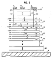
- Fig. 5 is a cross-section of a module which includes a wiring arrangement in accordance with the present invention.
- Fig. 5 schematically shows that the module includes a top element or plane T which supports one or more electrical or electronic devices. These are schematically represented at H1, H2 and H3.
- Each of these electrical or electronic devices H1-H3, which may comprise for example semiconductor chips, are conductively connected to a wiring pattern which may be supported on the plane or layer T.
- the wiring arrangement of the present invention is arranged to provide for connecting terminals of the various electrical or electronic devices, such as terminals T1 and T2. More particularly, the wiring arrangement includes a plurality of sets of wiring planes including for example sets S1, S2, S3 and S4. As shown in Fig.
- each of the sets comprises a pair of wiring planes.
- the set S1 includes wiring planes 1a and 1b which comprise the wiring planes 10 and 30, respectively.
- Set S2, including planes 2a and 2b, may for example comprise the planes 30 and 20, respectively.
- Set S3 includes planes 20 and 40 while set S4 includes planes 40 and 10.
- the planes 10-40 as used in Fig. 5 differ from those shown in Figs. 1- 4 in that some of the conductor tracks X1-X4, Y1-Y4 and D1-D10 have had printed circuit wiring or conductive patterns laid therein along with conductive connection between selected conductive patterns and selected connection sites C.
- Each of the sets of wiring planes may be separated from an adjacent set by a reference plane such as reference planes R1-R4.
- the reference planes are provided, as is relatively conventional in the art, for preventing electrical cross-talk between wiring planes in different sets.
- the reference planes include three major components, a substrate, a plurality of vias or holes allowing conductive paths to pass therethrough, and a conductive pattern supported on the substrate but insulated from the vias.
- FIG. 5 The cross-section of Fig. 5 is intended to represent the wiring arrangement including the sets of wiring planes S1-S4 and its relationship to the top plane T.
- a typical module will include, in addition to the foregoing structure, a plurality of signal- redistribution and power planes (and possibly an additional reference plane R0) represented as the group of planes M1. Furthermore, a typical module may include power distribution planes represented as the set of planes M3. In addition, in the unillustrated planes identified in the region M2, other plane pairs or a duplication of one or more of the sets S1-S4 may be provided.
- the module finally includes a bottom surface B which may provide connectors to a next level package, mother board or the like.
- FIG. 5 A typical interconnection of the terminals T1 and T2 is shown in Fig. 5. More particularly, the terminal T1 is connected to a conductive element or pin P1, at one end of the pin P1. The other end of the pin P1 is connected to a particular connection site C3 of the wiring plane 2a. Holes in planes between planes T and 2a allow the pin P1 to remain insulated from intervening components. Although not shown in Fig. 5, the connection site C3 is connected to a particular conductor on the wiring plane 2a. Another point on the same particular conductor is connected to a different connection site C4. The connection site C4 is connected to one end of a programmable via V or a short pin V. The same via V is connected to a connection site C5 on the plane 2b.
- connection site C5 is connected to a particular conductor on the plane 2b, and another point on the same particular conductor is connected to connection site C6.
- the connection site C6 is connected to a further conductive element or a pin P2 at one end. The other end of the pin P2 is connected to the terminal T2.
- Fig. 6 is another cross-section, similar to Fig. 5, but showing a different use of the sets of planes for connecting terminals of electrical or electronic devices in accordance with the present invention.
- the particular connection illustrated in Fig. 5, in cross-section, used a single via and thus one terminal of one electrical or electronic device was connected to a first wiring plane 2a and a terminal of a second electrical or electronic device was connected to a different plane 2b, of the same pair.
- the particular connection shown in Fig. 6 uses vias V1 and V2 so that the two different terminals of the electrical or electronic devices being interconnected are respec tively connected to the same wiring plane. More particularly, and as shown in Fig.
- the pin P1 connects a terminal of the electronic or electrical device H1 to a connection site C7 on the plane S2a.
- a conductor on the plane S2a is connected between the connection sites C7 and C8.
- a via V1 connects the connection site C8 to a connection site C9 on a plane S2b.
- Connection site C9 is connected by a conductor on the plane S2b to a connection site C10.
- a via V2 is connected between the connection site C10 and a connection site C11 on the plane S2a.
- Another conductor on the plane S2a is connected between the connection sites C11 and C12.
- the pin P2 is connected between a terminal of the electronic or electrical device H3 and a connection site C12.
- the wiring arrangement described herein provides for connecting a plurality of electrical or electronic devices, e.g. the devices H1 and H3 which are supported on the top surface of common plane T.
- the wiring arrangement includes plural sets (S1-S4 in Fig. 5) of wiring planes, each of the wiring planes supports conductive wiring oriented in a principal wiring direction and further supports a plurality of connection sites C arranged at intersections of theoretical orthogonal lines.
- the pins such as P1 and P2 interconnect selected devices with selected ones of the connection points on the same or different ones of the wiring planes. Every connection uses planes within one and only one set of planes.
- Each of the sets of wiring planes includes at least first and second wiring planes.
- the reader can verify that in each of the sets shown in Fig. 5, a principal direction of wiring in a first wiring plane lies at an acute angle to a principal direction of wiring on the second wiring plane.
- the wiring planes 1a, 2b, 3a and 4b as first wiring planes, it will be realized that the wiring directions on all of these planes are orthogonal or parallel to each other.
- the planes 1b, 2a, 3b and 4a as second wiring planes, the reader can verify that the principal direction of wiring of these planes is either parallel or orthogonal to each other.
- the principal direction of wiring on the planes 1a, 2b, 3a and 4b are parallel or orthogonal to one of the edges of the module.
- the principal wiring direction of the planes 1b, 2a, 3b and 4a form an acute angle, are oblique or diagonal, with or to at least one of the edges of the module.
- the invention is not limited to sets of wiring planes fashioned from pairs of planes selected from the planes 10-40 (of Figs. 1-4). More particularly, in the embodiment of Figs. 1- 4 the acute angle between the principal wiring directions of a pair of planes in set is 45°; other different acute angles could also be employed, e.g. 30°, 60°, etc. In the embodiment shown in Fig. 5, one plane of each pair has a principal wiring direction which is either parallel to or orthogonal to a principal wiring direction of one of the planes in each other set. Likewise, this is not an essential characteristic of the invention.
- I provide a set of wiring planes with principal wiring directions at angles of 0°, 60° and 120° to the abscissa in a Cartesian coordinate system (which is parallel to one of the edges of the wiring plane).
- a first plane pair has principal wiring directions of 0° and 60°
- a second pair has principal wiring directions of 60° and 120°
- a third plane pair has principal wiring directions of 120° and 0° (or 180° which is identical to 0°).
- each plane pair In a more general construction of a wiring arrangement where there are n + 1 wiring plane pairs, the principal wiring directions in each plane pair are 0°, z° (for a first pair), z°, 2z° (for a second pair), 2z°, 3z° (for a third pair), and repeating in this fashion until nz°, 180° (or 0°) for the last plane pair, where z is the quantity (180/n+1). If n is an integer greater than one, then each pair of planes has principal wiring directions which make an angle of z° with each other, and z° is an acute angle. Considering the wiring directions of any pair, there is at least one non-identical pair which has a common wiring direction with one of the planes of the pair.
- a first set used principal wiring directions of 0°, 45° and 90° and a second set uses planes at 90°, 135° and 180°.
- the invention provides for a reduction (by about 10% or more) in interconnection wiring and approximately 17%-30% reduction in the number of wiring planes required.
- the collection of wiring planes employed use principal wiring directions which are referenced as X (0°), 45°, Y (90°) and 135°, respectively, with reference to a Cartesian coordinate system.
- the oblique planes (with principal wiring directions at 45° and 135° respectively) include jogs or meanders to clear connection sites C.
- the wiring arrangement includes at a minimum four pairs of wiring planes oriented as, in a first pair, X (0°) and 45°, a second pair at 45°, Y (90°), a third pair at Y (90°), 135°, and a fourth pair at 135°, X (0°).
- the minimum set can of course be repeated to provide the necessary wiring capacity.
- a two pin connection between different electrical or electronic devices is assigned to one of the plane pairs whose two preferred axes (or principal wiring directions) lie closest to the orientation of the connection between the terminals drawn as a straight line.
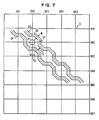
- Fig. 7 shows two of the conductors D3 and D4 typical of one of the two oblique planes 30 and 40.
- Fig. 7 is drawn for a "worst case" situation in which the wire width W, required clearance from connection sites, and grid spacing (between adjacent connection sites) are such that the conductive pattern cannot run obliquely between adjacent connection sites C.
- the connection site diameter C D plus the wire width W, plus twice the required connection site clearance is equal to the distance between adjacent connection sites C. This is the minimum condition needed for the usual orthogonal wiring with one line per wiring channel.
- connection possibilities including Euclidean or straight line length (referred to as EUCL), a minimum-Manhattan length e.g. along orthogonal axes in a Cartesian coordinate system (represented as MANH), the minimum connection length for the shortest route lying along the principal wiring directions used in accordance with the present invention, but ignoring the additional length required for jogs or meander (represented as L45) and the actual connection length for the same route including jogs or meanders (represented as L45J).
- EUCL Euclidean or straight line length
- MANH minimum-Manhattan length e.g. along orthogonal axes in a Cartesian coordinate system
- L45 the minimum connection length for the shortest route lying along the principal wiring directions used in accordance with the present invention, but ignoring the additional length required for jogs or meander
- L45J the actual connection length for the same route including jogs or meanders
- next ratio indicates that employing the present invention reduces the required wiring by about 17% compared to the minimum Manhattan length (ignoring the length required for meanders and jogs).
- the last ratio indicates that even if we include the additional wiring length caused by the need for meanders or jogs, we are still 10% below the minimum Manhattan length.
- ratios 4, 5, 9, 10, 14 and 15 were achieved without requiring any change in wire width W and minimum wiring spacing S or the grid spacing of connection sites. This is achieved by choosing the jog segments of each of the oblique running wires to lie at 0° and 90° to the theoretical orthogonal lines at the intersections of which the connection sites lie. For example, the segment SX is perpendicular to the theoretical line OV2 and the segment SY is perpendicular to the line OH2, etc. The distance of closest approach between a wire segment and a connection site is therefore the same as in the usual X-Y wiring case. If the grid spacing is even slightly larger than minimum, additional performance and wire length improvements are realized by running the jog segments at angles closer to 45°. In a limit at which no jogs are required, a 17% reduction below minimum Manhattan length would result (ratio 4).
- the minimum spacing between adjacent diagonal wire segments within a plane must be consistent with fabrication tolerances in order to avoid creating electrical shorts. In units of the grid spacing (of Fig. 6), the minimum interwire spacing is 0.414 - W.
- the total connection length (ignoring jogs) is reduced by approximately 17% when four different principal wiring directions (x, y, 45°, 135°) are used in accordance with the present invention, as compared with minimum manhattan length. This total connection length, ignoring jogs, determines how much of the wiring tracks is occupied by wire, and leads to an approximately 17% reduction in the required number of wiring planes.
- the second effect which reduces the necessary number of wiring planes is the fact that diagonal or oblique wiring provides for a wire track capacity (between adjacent connection sites C) which is 1.414 times that for wiring planes whose principal wiring direction is along the Cartesian coordinate axes.
- the wiring plane whose principal wiring direction was parallel to one of the Cartesian coordinate axes of a module of side length M would carry a length of wire equal to M2, where the spacing between adjacent wiring tracks is one unit of length.
- an oblique plane (with the principal wiring direction at 45° to the Cartesian coordinate axes) would carry 1.414 M2 length of wire (ignoring the wire length required by jogs or meanders).
Landscapes
- Engineering & Computer Science (AREA)
- Microelectronics & Electronic Packaging (AREA)
- Design And Manufacture Of Integrated Circuits (AREA)
- Structure Of Printed Boards (AREA)
- Production Of Multi-Layered Print Wiring Board (AREA)
Applications Claiming Priority (2)
| Application Number | Priority Date | Filing Date | Title |
|---|---|---|---|
| US101228 | 1987-09-25 | ||
| US07/101,228 US4782193A (en) | 1987-09-25 | 1987-09-25 | Polygonal wiring for improved package performance |
Publications (3)
| Publication Number | Publication Date |
|---|---|
| EP0308714A2 true EP0308714A2 (de) | 1989-03-29 |
| EP0308714A3 EP0308714A3 (en) | 1989-08-09 |
| EP0308714B1 EP0308714B1 (de) | 1992-11-25 |
Family
ID=22283602
Family Applications (1)
| Application Number | Title | Priority Date | Filing Date |
|---|---|---|---|
| EP88114456A Expired EP0308714B1 (de) | 1987-09-25 | 1988-09-05 | Verdrahtungssystem für die Verbindung von mehreren elektrischen oder elektronischen Anordnungen |
Country Status (4)
| Country | Link |
|---|---|
| US (1) | US4782193A (de) |
| EP (1) | EP0308714B1 (de) |
| JP (1) | JPH0196953A (de) |
| DE (1) | DE3876195T2 (de) |
Cited By (7)
| Publication number | Priority date | Publication date | Assignee | Title |
|---|---|---|---|---|
| EP0353114A1 (de) * | 1988-07-13 | 1990-01-31 | Thomson-Csf | Verbindungsvorrichtung zwischen einer integrierten Schaltung und einer elektrischen Schaltung und Herstellungsverfahren derselben |
| EP0405755A3 (en) * | 1989-05-31 | 1992-08-26 | Fujitsu Limited | Pin grid array packaging structure |
| FR2702595A1 (fr) * | 1993-03-11 | 1994-09-16 | Toshiba Kk | Structure de câblage multicouche. |
| EP0614220A3 (de) * | 1993-03-01 | 1995-03-01 | Univ Arkansas | Mehrchipmodul. |
| EP0883182A3 (de) * | 1997-06-05 | 1999-06-16 | Shinko Electric Industries Co. Ltd. | Gitteranordnung der Elektroden auf einer Mehrlagenleiterplatte |
| EP0928029A3 (de) * | 1997-12-22 | 1999-12-22 | Shinko Electric Industries Co. Ltd. | Mehrlagenschaltungs-Design |
| EP0921567A3 (de) * | 1997-11-19 | 2000-05-10 | Shinko Electric Industries Co. Ltd. | Mehrschicht-Schaltungsplatte |
Families Citing this family (71)
| Publication number | Priority date | Publication date | Assignee | Title |
|---|---|---|---|---|
| JPH0714024B2 (ja) * | 1990-11-29 | 1995-02-15 | 川崎製鉄株式会社 | マルチチップモジュール |
| US5341310A (en) * | 1991-12-17 | 1994-08-23 | International Business Machines Corporation | Wiring layout design method and system for integrated circuits |
| JP2759573B2 (ja) * | 1992-01-23 | 1998-05-28 | 株式会社日立製作所 | 回路基板の配線パターン決定方法 |
| US5360948A (en) * | 1992-08-14 | 1994-11-01 | Ncr Corporation | Via programming for multichip modules |
| DE19652258A1 (de) * | 1996-12-16 | 1998-06-18 | Ibm | Verbesserte Verdrahtungsstruktur für Hochleistungschips |
| JP3184796B2 (ja) * | 1998-03-19 | 2001-07-09 | インターナショナル・ビジネス・マシーンズ・コーポレ−ション | 配線設計装置およびその方法 |
| US6483714B1 (en) | 1999-02-24 | 2002-11-19 | Kyocera Corporation | Multilayered wiring board |
| US6898773B1 (en) | 2002-01-22 | 2005-05-24 | Cadence Design Systems, Inc. | Method and apparatus for producing multi-layer topological routes |
| US6889372B1 (en) | 2000-07-15 | 2005-05-03 | Cadence Design Systems Inc. | Method and apparatus for routing |
| US6957410B2 (en) | 2000-12-07 | 2005-10-18 | Cadence Design Systems, Inc. | Method and apparatus for adaptively selecting the wiring model for a design region |
| US7003754B2 (en) | 2000-12-07 | 2006-02-21 | Cadence Design Systems, Inc. | Routing method and apparatus that use of diagonal routes |
| US7073150B2 (en) | 2000-12-07 | 2006-07-04 | Cadence Design Systems, Inc. | Hierarchical routing method and apparatus that use diagonal routes |
| US6900540B1 (en) * | 2000-12-07 | 2005-05-31 | Cadence Design Systems, Inc. | Simulating diagonal wiring directions using Manhattan directional wires |
| US6858928B1 (en) * | 2000-12-07 | 2005-02-22 | Cadence Design Systems, Inc. | Multi-directional wiring on a single metal layer |
| US6915501B2 (en) | 2001-01-19 | 2005-07-05 | Cadence Design Systems, Inc. | LP method and apparatus for identifying routes |
| US6883154B2 (en) | 2001-01-19 | 2005-04-19 | Cadence Design Systems, Inc. | LP method and apparatus for identifying route propagations |
| US6895569B1 (en) | 2001-06-03 | 2005-05-17 | Candence Design Systems, Inc. | IC layout with non-quadrilateral Steiner points |
| US7107564B1 (en) | 2001-06-03 | 2006-09-12 | Cadence Design Systems, Inc. | Method and apparatus for routing a set of nets |
| US6859916B1 (en) | 2001-06-03 | 2005-02-22 | Cadence Design Systems, Inc. | Polygonal vias |
| US7310793B1 (en) | 2001-06-03 | 2007-12-18 | Cadence Design Systems, Inc. | Interconnect lines with non-rectilinear terminations |
| US6877146B1 (en) | 2001-06-03 | 2005-04-05 | Cadence Design Systems, Inc. | Method and apparatus for routing a set of nets |
| US6976238B1 (en) | 2001-06-03 | 2005-12-13 | Cadence Design Systems, Inc. | Circular vias and interconnect-line ends |
| US6895567B1 (en) * | 2001-06-03 | 2005-05-17 | Cadence Design Systems, Inc. | Method and arrangement for layout of gridless nonManhattan semiconductor integrated circuit designs |
| US6957408B1 (en) | 2002-01-22 | 2005-10-18 | Cadence Design Systems, Inc. | Method and apparatus for routing nets in an integrated circuit layout |
| US6951005B1 (en) | 2001-06-03 | 2005-09-27 | Cadence Design Systems, Inc. | Method and apparatus for selecting a route for a net based on the impact on other nets |
| US6957411B1 (en) | 2001-06-03 | 2005-10-18 | Cadence Design Systems, Inc. | Gridless IC layout and method and apparatus for generating such a layout |
| US6882055B1 (en) | 2001-06-03 | 2005-04-19 | Cadence Design Systems, Inc. | Non-rectilinear polygonal vias |
| US7069530B1 (en) | 2001-06-03 | 2006-06-27 | Cadence Design Systems, Inc. | Method and apparatus for routing groups of paths |
| US6931616B2 (en) * | 2001-08-23 | 2005-08-16 | Cadence Design Systems, Inc. | Routing method and apparatus |
| US7398498B2 (en) | 2001-08-23 | 2008-07-08 | Cadence Design Systems, Inc. | Method and apparatus for storing routes for groups of related net configurations |
| US6795958B2 (en) * | 2001-08-23 | 2004-09-21 | Cadence Design Systems, Inc. | Method and apparatus for generating routes for groups of related node configurations |
| US7143382B2 (en) | 2001-08-23 | 2006-11-28 | Cadence Design Systems, Inc. | Method and apparatus for storing routes |
| US7155697B2 (en) | 2001-08-23 | 2006-12-26 | Cadence Design Systems, Inc. | Routing method and apparatus |
| US6762489B2 (en) * | 2001-11-20 | 2004-07-13 | International Business Machines Corporation | Jogging structure for wiring translation between grids with non-integral pitch ratios in chip carrier modules |
| US6938234B1 (en) | 2002-01-22 | 2005-08-30 | Cadence Design Systems, Inc. | Method and apparatus for defining vias |
| US7096449B1 (en) | 2002-01-22 | 2006-08-22 | Cadence Design Systems, Inc. | Layouts with routes with different widths in different directions on the same layer, and method and apparatus for generating such layouts |
| US7013451B1 (en) | 2002-01-22 | 2006-03-14 | Cadence Design Systems, Inc. | Method and apparatus for performing routability checking |
| US7080329B1 (en) | 2002-01-22 | 2006-07-18 | Cadence Design Systems, Inc. | Method and apparatus for identifying optimized via locations |
| US7089524B1 (en) | 2002-01-22 | 2006-08-08 | Cadence Design Systems, Inc. | Topological vias route wherein the topological via does not have a coordinate within the region |
| US6892371B1 (en) | 2002-01-22 | 2005-05-10 | Cadence Design Systems, Inc. | Method and apparatus for performing geometric routing |
| US6944841B1 (en) | 2002-01-22 | 2005-09-13 | Cadence Design Systems, Inc. | Method and apparatus for proportionate costing of vias |
| US6973634B1 (en) | 2002-01-22 | 2005-12-06 | Cadence Design Systems, Inc. | IC layouts with at least one layer that has more than one preferred interconnect direction, and method and apparatus for generating such a layout |
| US7117468B1 (en) | 2002-01-22 | 2006-10-03 | Cadence Design Systems, Inc. | Layouts with routes with different spacings in different directions on the same layer, and method and apparatus for generating such layouts |
| US6988257B2 (en) * | 2002-11-18 | 2006-01-17 | Cadence Design Systems, Inc. | Method and apparatus for routing |
| US7171635B2 (en) * | 2002-11-18 | 2007-01-30 | Cadence Design Systems, Inc. | Method and apparatus for routing |
| US7093221B2 (en) * | 2002-11-18 | 2006-08-15 | Cadence Design Systems, Inc. | Method and apparatus for identifying a group of routes for a set of nets |
| US7624367B2 (en) | 2002-11-18 | 2009-11-24 | Cadence Design Systems, Inc. | Method and system for routing |
| US7010771B2 (en) * | 2002-11-18 | 2006-03-07 | Cadence Design Systems, Inc. | Method and apparatus for searching for a global path |
| US6996789B2 (en) * | 2002-11-18 | 2006-02-07 | Cadence Design Systems, Inc. | Method and apparatus for performing an exponential path search |
| US7480885B2 (en) | 2002-11-18 | 2009-01-20 | Cadence Design Systems, Inc. | Method and apparatus for routing with independent goals on different layers |
| US6892369B2 (en) * | 2002-11-18 | 2005-05-10 | Cadence Design Systems, Inc. | Method and apparatus for costing routes of nets |
| US7080342B2 (en) * | 2002-11-18 | 2006-07-18 | Cadence Design Systems, Inc | Method and apparatus for computing capacity of a region for non-Manhattan routing |
| US7003752B2 (en) * | 2002-11-18 | 2006-02-21 | Cadence Design Systems, Inc. | Method and apparatus for routing |
| US7216308B2 (en) * | 2002-11-18 | 2007-05-08 | Cadence Design Systems, Inc. | Method and apparatus for solving an optimization problem in an integrated circuit layout |
| US7047513B2 (en) * | 2002-11-18 | 2006-05-16 | Cadence Design Systems, Inc. | Method and apparatus for searching for a three-dimensional global path |
| US7373628B1 (en) | 2004-06-01 | 2008-05-13 | Pulsic Limited | Method of automatically routing nets using a Steiner tree |
| US7131096B1 (en) | 2004-06-01 | 2006-10-31 | Pulsic Limited | Method of automatically routing nets according to current density rules |
| US8095903B2 (en) * | 2004-06-01 | 2012-01-10 | Pulsic Limited | Automatically routing nets with variable spacing |
| US7784010B1 (en) | 2004-06-01 | 2010-08-24 | Pulsic Limited | Automatic routing system with variable width interconnect |
| US7257797B1 (en) | 2004-06-07 | 2007-08-14 | Pulsic Limited | Method of automatic shape-based routing of interconnects in spines for integrated circuit design |
| US7168053B1 (en) | 2004-12-29 | 2007-01-23 | Cadence Design Systems, Inc. | Method and system for implementing an analytical wirelength formulation |
| US7107556B1 (en) * | 2004-12-29 | 2006-09-12 | Cadence Design Systems, Inc. | Method and system for implementing an analytical wirelength formulation for unavailability of routing directions |
| US9245082B2 (en) | 2005-06-21 | 2016-01-26 | Pulsic Limited | High-speed shape-based router |
| US7603644B2 (en) | 2005-06-24 | 2009-10-13 | Pulsic Limited | Integrated circuit routing and compaction |
| US7363607B2 (en) * | 2005-11-08 | 2008-04-22 | Pulsic Limited | Method of automatically routing nets according to parasitic constraint rules |
| US8201128B2 (en) | 2006-06-16 | 2012-06-12 | Cadence Design Systems, Inc. | Method and apparatus for approximating diagonal lines in placement |
| US8250514B1 (en) | 2006-07-13 | 2012-08-21 | Cadence Design Systems, Inc. | Localized routing direction |
| JP2009122474A (ja) | 2007-11-16 | 2009-06-04 | Mitsubishi Electric Corp | 液晶表示装置及びその製造方法 |
| US8011950B2 (en) | 2009-02-18 | 2011-09-06 | Cinch Connectors, Inc. | Electrical connector |
| US8458636B1 (en) | 2009-03-18 | 2013-06-04 | Pulsic Limited | Filling vacant areas of an integrated circuit design |
| KR20220145988A (ko) | 2021-04-22 | 2022-11-01 | 삼성전자주식회사 | 반도체 장치 |
Family Cites Families (8)
| Publication number | Priority date | Publication date | Assignee | Title |
|---|---|---|---|---|
| US3179913A (en) * | 1962-01-25 | 1965-04-20 | Ind Electronic Hardware Corp | Rack with multilayer matrix boards |
| US3470612A (en) * | 1966-11-14 | 1969-10-07 | Texas Instruments Inc | Method of making multilayer circuit boards |
| JPS5530822A (en) * | 1978-08-25 | 1980-03-04 | Fujitsu Ltd | Printed board |
| US4254445A (en) * | 1979-05-07 | 1981-03-03 | International Business Machines Corporation | Discretionary fly wire chip interconnection |
| US4302625A (en) * | 1980-06-30 | 1981-11-24 | International Business Machines Corp. | Multi-layer ceramic substrate |
| JPS5818950A (ja) * | 1981-07-28 | 1983-02-03 | Nec Corp | 多層配線基板 |
| JPS60136294A (ja) * | 1983-12-23 | 1985-07-19 | 株式会社日立製作所 | セラミック多層配線回路板 |
| US4535388A (en) * | 1984-06-29 | 1985-08-13 | International Business Machines Corporation | High density wired module |
-
1987
- 1987-09-25 US US07/101,228 patent/US4782193A/en not_active Expired - Fee Related
-
1988
- 1988-07-20 JP JP63179343A patent/JPH0196953A/ja active Pending
- 1988-09-05 EP EP88114456A patent/EP0308714B1/de not_active Expired
- 1988-09-05 DE DE8888114456T patent/DE3876195T2/de not_active Expired - Fee Related
Cited By (16)
| Publication number | Priority date | Publication date | Assignee | Title |
|---|---|---|---|---|
| EP0353114A1 (de) * | 1988-07-13 | 1990-01-31 | Thomson-Csf | Verbindungsvorrichtung zwischen einer integrierten Schaltung und einer elektrischen Schaltung und Herstellungsverfahren derselben |
| EP0405755A3 (en) * | 1989-05-31 | 1992-08-26 | Fujitsu Limited | Pin grid array packaging structure |
| US6255600B1 (en) | 1993-03-01 | 2001-07-03 | The Board Of Trustees Of The University Of Arkansas | Electronic interconnection medium having offset electrical mesh plane |
| US6388200B2 (en) | 1993-03-01 | 2002-05-14 | The Board Of Trustees Of The University Of Arkansas | Electronic interconnection medium having offset electrical mesh plane |
| EP0614220A3 (de) * | 1993-03-01 | 1995-03-01 | Univ Arkansas | Mehrchipmodul. |
| US6297460B1 (en) | 1993-03-01 | 2001-10-02 | The Board Of Trustees Of The University Of Arkansas | Multichip module and method of forming same |
| US5723908A (en) * | 1993-03-11 | 1998-03-03 | Kabushiki Kaisha Toshiba | Multilayer wiring structure |
| FR2702595A1 (fr) * | 1993-03-11 | 1994-09-16 | Toshiba Kk | Structure de câblage multicouche. |
| US6229099B1 (en) | 1997-06-05 | 2001-05-08 | Shinko Electric Industries Co., Ltd. | Multi-layer circuit board with particular pad spacing |
| EP0883182A3 (de) * | 1997-06-05 | 1999-06-16 | Shinko Electric Industries Co. Ltd. | Gitteranordnung der Elektroden auf einer Mehrlagenleiterplatte |
| US6452115B2 (en) | 1997-06-05 | 2002-09-17 | Shinko Electric Industries Co., Ltd | Circuit pattern for multi-layer circuit board for mounting electronic parts |
| EP0921567A3 (de) * | 1997-11-19 | 2000-05-10 | Shinko Electric Industries Co. Ltd. | Mehrschicht-Schaltungsplatte |
| US6271478B1 (en) | 1997-11-19 | 2001-08-07 | Shinko Electric Industries Co., Ltd. | Multi-layer circuit board |
| US6194668B1 (en) | 1997-12-22 | 2001-02-27 | Shinko Electric Industries Co., Ltd. | Multi-layer circuit board |
| EP0928029A3 (de) * | 1997-12-22 | 1999-12-22 | Shinko Electric Industries Co. Ltd. | Mehrlagenschaltungs-Design |
| KR100309961B1 (ko) * | 1997-12-22 | 2001-11-17 | 모기 쥰이찌 | 다층 회로 기판 |
Also Published As
| Publication number | Publication date |
|---|---|
| US4782193A (en) | 1988-11-01 |
| EP0308714B1 (de) | 1992-11-25 |
| JPH0196953A (ja) | 1989-04-14 |
| DE3876195T2 (de) | 1993-06-03 |
| EP0308714A3 (en) | 1989-08-09 |
| DE3876195D1 (de) | 1993-01-07 |
Similar Documents
| Publication | Publication Date | Title |
|---|---|---|
| EP0308714B1 (de) | Verdrahtungssystem für die Verbindung von mehreren elektrischen oder elektronischen Anordnungen | |
| EP0644596B1 (de) | Auslegungsmethode für mehrlagige gedruckte Schaltung | |
| EP0083406B1 (de) | Modul zum Tragen elektrischer Bausteine | |
| US6150729A (en) | Routing density enhancement for semiconductor BGA packages and printed wiring boards | |
| US4254445A (en) | Discretionary fly wire chip interconnection | |
| US5155577A (en) | Integrated circuit carriers and a method for making engineering changes in said carriers | |
| US4689441A (en) | Routing method and pattern for reducing cross talk noise problems on printed interconnection boards | |
| US6416333B1 (en) | Extension boards and method of extending boards | |
| US5397861A (en) | Electrical interconnection board | |
| JPH0750817B2 (ja) | 配線相互接続構造体 | |
| US4535388A (en) | High density wired module | |
| US4004196A (en) | Multi-layer panel board with single-in-line package for high speed switching logic | |
| US6703706B2 (en) | Concurrent electrical signal wiring optimization for an electronic package | |
| US6382983B2 (en) | Module mounting system | |
| US6956286B2 (en) | Integrated circuit package with overlapping bond fingers | |
| US6662250B1 (en) | Optimized routing strategy for multiple synchronous bus groups | |
| TW569362B (en) | Wiring designing method and semiconductor device | |
| EP0624055B1 (de) | Energiezuführungsstruktur für ein Multichip | |
| US8125087B2 (en) | High-density flip-chip interconnect | |
| US6218865B1 (en) | Semiconductor device having function blocks with obliquely arranged signal terminals connected through two-dimensionally extensible signal lines | |
| JP2947219B2 (ja) | スタンダードセル方式の半導体集積回路の配線構造 | |
| JP3600159B2 (ja) | Icチップ | |
| JPS6064448A (ja) | 半導体装置 | |
| JP2004259293A (ja) | 配線設計装置 | |
| CN121310396A (zh) | 硅基板信号优化布线结构及电子设备 |
Legal Events
| Date | Code | Title | Description |
|---|---|---|---|
| PUAI | Public reference made under article 153(3) epc to a published international application that has entered the european phase |
Free format text: ORIGINAL CODE: 0009012 |
|
| AK | Designated contracting states |
Kind code of ref document: A2 Designated state(s): DE FR GB |
|
| PUAL | Search report despatched |
Free format text: ORIGINAL CODE: 0009013 |
|
| AK | Designated contracting states |
Kind code of ref document: A3 Designated state(s): DE FR GB |
|
| 17P | Request for examination filed |
Effective date: 19890720 |
|
| 17Q | First examination report despatched |
Effective date: 19910403 |
|
| GRAA | (expected) grant |
Free format text: ORIGINAL CODE: 0009210 |
|
| AK | Designated contracting states |
Kind code of ref document: B1 Designated state(s): DE FR GB |
|
| PG25 | Lapsed in a contracting state [announced via postgrant information from national office to epo] |
Ref country code: FR Free format text: THE PATENT HAS BEEN ANNULLED BY A DECISION OF A NATIONAL AUTHORITY Effective date: 19921125 |
|
| REF | Corresponds to: |
Ref document number: 3876195 Country of ref document: DE Date of ref document: 19930107 |
|
| ET | Fr: translation filed | ||
| PG25 | Lapsed in a contracting state [announced via postgrant information from national office to epo] |
Ref country code: GB Effective date: 19930905 |
|
| PLBE | No opposition filed within time limit |
Free format text: ORIGINAL CODE: 0009261 |
|
| STAA | Information on the status of an ep patent application or granted ep patent |
Free format text: STATUS: NO OPPOSITION FILED WITHIN TIME LIMIT |
|
| 26N | No opposition filed | ||
| GBPC | Gb: european patent ceased through non-payment of renewal fee |
Effective date: 19930905 |
|
| PG25 | Lapsed in a contracting state [announced via postgrant information from national office to epo] |
Ref country code: DE Effective date: 19940601 |
|
| REG | Reference to a national code |
Ref country code: FR Ref legal event code: ST |