EP0306981B1 - Dauermagnet zur Beschleunigung von korpuskularen Strahlen - Google Patents
Dauermagnet zur Beschleunigung von korpuskularen Strahlen Download PDFInfo
- Publication number
- EP0306981B1 EP0306981B1 EP88114799A EP88114799A EP0306981B1 EP 0306981 B1 EP0306981 B1 EP 0306981B1 EP 88114799 A EP88114799 A EP 88114799A EP 88114799 A EP88114799 A EP 88114799A EP 0306981 B1 EP0306981 B1 EP 0306981B1
- Authority
- EP
- European Patent Office
- Prior art keywords
- permanent magnet
- accelerating
- corpuscular beam
- beam according
- ray
- Prior art date
- Legal status (The legal status is an assumption and is not a legal conclusion. Google has not performed a legal analysis and makes no representation as to the accuracy of the status listed.)
- Expired - Lifetime
Links
Images

Classifications
-
- H—ELECTRICITY
- H01—ELECTRIC ELEMENTS
- H01F—MAGNETS; INDUCTANCES; TRANSFORMERS; SELECTION OF MATERIALS FOR THEIR MAGNETIC PROPERTIES
- H01F1/00—Magnets or magnetic bodies characterised by the magnetic materials therefor; Selection of materials for their magnetic properties
- H01F1/01—Magnets or magnetic bodies characterised by the magnetic materials therefor; Selection of materials for their magnetic properties of inorganic materials
- H01F1/03—Magnets or magnetic bodies characterised by the magnetic materials therefor; Selection of materials for their magnetic properties of inorganic materials characterised by their coercivity
- H01F1/032—Magnets or magnetic bodies characterised by the magnetic materials therefor; Selection of materials for their magnetic properties of inorganic materials characterised by their coercivity of hard-magnetic materials
- H01F1/04—Magnets or magnetic bodies characterised by the magnetic materials therefor; Selection of materials for their magnetic properties of inorganic materials characterised by their coercivity of hard-magnetic materials metals or alloys
- H01F1/047—Alloys characterised by their composition
- H01F1/053—Alloys characterised by their composition containing rare earth metals
- H01F1/055—Alloys characterised by their composition containing rare earth metals and magnetic transition metals, e.g. SmCo5
- H01F1/057—Alloys characterised by their composition containing rare earth metals and magnetic transition metals, e.g. SmCo5 and IIIa elements, e.g. Nd2Fe14B
Definitions
- the present invention relates to a permanent magnet for accelerating corpuscular beam used in a wiggler, undulator, traveling-wave tube, magnetron, cyclotron, etc., and is particularly characterized by a magnet of fine-grain type which is able to resist damage caused by radioactive rays.
- a permanent magnet for accelerating a corpuscular beam is required to generate a strong magnetic field in a space (space magnetic field) and to resist damage caused by any radioactive rays generated or leaked.
- R-Co type magnets composed of a rare earth element (referred to as "R” hereinafter) and cobalt have generally been used as permanent magnets capable of generating strong space magnetic fields.
- R rare earth element
- cobalt cobalt
- the strength of the space magnetic field generated by such a permanent magnet depends upon the quality of the magnetic circuit design, and is only about 2000 gauss.
- Nd-Fe-B type magnets which generate stronger space magnetic fields than with a conventional R-Co type magnet have appeared (refer to Japanese Patent Laid-Open No. 46008/1984).
- Nd-Fe-B type magnet it may be considered that it is desirable to use such a Nd-Fe-B type magnet because it generates a strong space magnetic field and has resistance to damage caused by radioactive rays owing to the fact that only a small amount of Co is contained therein.
- Undulator apparatus generate very high-frequency X rays with wave length of 0.1 to 10 nm when an electron beam is accelerated and deflected by a series of permanent magnets and is used in lithographic apparatus for semiconductors.
- Wigglers are basically similar to such undulators but differ from them in the point that they generate beam with a wavelength as short as 0.1 to 0.001 nm.
- the wiggler is an apparatus which generates free electron laser.
- Nd-Fe-B magnets are sintered magnets produced by a powder metallurgy method and so-called nucleation-type permanent magnets (European Patent Laid-Open Publication No. 0101552).
- Such types of permanent magnet manifest their magnetism by virtue of a rich Nd phase surrounding a principal phase represented by Nd2Fe14B, and they attain sufficient coercive force only when the grains for constituting the magnet are ground to a size near the critical radius of a single magnetic domain (about 0.3 ⁇ m). It is thought to be ideal for the principal phases to be separated from each other by R-rich non-magnetic phases containing large amounts of R.
- a permanent magnet is of the nucleation type and if the composition thereof is changed, the permanent magnet is fundamentally incapable of avoiding radiation damage, which consequently limits its use as an accelerator for corpuscular beam.
- the inventors conceived an Nd-Fe-B type permanent magnet having a pinning type which is different from the conventional Nd-Fe-B type magnet and found that addition of Ga had the effect of providing the magnet with resistance to radiation damage and improving coercive force, leading to the improvement of the problems of conventional magnets.
- the present invention provides a permanent magnet for accelerating corpuscular beam which is represented by the composition formula R a Fe bal.
- R denotes at least one element selected from the group consisting of Nd, Pr, Dy, Tb, Ho and Ce
- the M denotes at least one element selected from the group consisting of Al, Si, Nb, Ta, Ti, Zr, Hf and W, with the proviso that 12 ⁇ a ⁇ 18, 0 ⁇ b ⁇ 30, 4 ⁇ c ⁇ 10, 0.01 ⁇ d ⁇ 3 and 0 ⁇ e ⁇ 2 in terms of atomic %
- said permanent magnet comprising fine crystal grains provided with magnetic anisotropy.
- EP-A-0 216 254 discloses a similar composition, it does not suggest a pinning type magnet having fine crystal grains which are provided with magnetic anisotropy, as specified in claim 1. The same is true of the disclosure in Patent Abstracts of Japan, Vol. II, No. 117 (E-498) (2564), April 11, 1987, which discloses the use of certain metals, including Ga and Al, as a baking aid in forming an R-Fe-B magnet.
- very fine crystal grains having grain sizes of 0.01 to 0.5 ⁇ m which are very much smaller than the 0.3 to 80 ⁇ m dimension of the grains obtained by a conventional powder metallurgy method can be obtained from an alloy melt having the above composition formula by a rapid quenching method.
- the flakes and powder obtained by the rapid quenching method are consolidated by means of a hot press and the like and then subjected to plastic deformation so as to provide magnetic anisotropy.
- the ratio of plastic working h0/h is defined by the ratio of the height h0 of a specimen before plastic working (for example, upsetting) to the height h of the specimen after plastic working (for example, upsetting), and it is preferable in cases of obtaining Br of 11 kG or more that the ratio of h0/h is 2 or more.
- Br is set at 11 kG or more because the value cannot be achieved by a sintering method using a longitudinal magnetic press and can be achieved for the first time by the present invention.
- Ce is contained in an inexpensive material such as didymium. If the amount of Ce added is small (Ce/R ⁇ 0.1), the magnetic characteristics of a resultant magnet are not adversely affected.
- Dy, Tb and Ho serve to effectively improve the coercive force.
- (Tb + Dy)/R ⁇ 0.3 must be satisfied in order to achieve the condition of Br being 11 kG or more.
- Co replaces Fe to increase the Curie point of the magnetic phase.
- Addition of Co together with Ga improves both the temperature coefficient of Br and the irreversible demagnetizing factor at high temperatures.
- the amount of B is less than 4 at%, the R2Fe14B phase is not sufficiently formed as a principal phase, while if the amount exceeds 11 at%, the value of Br is reduced due to the occurrence of phases that are undesirable with respect to the magnetic characteristics.
- Ga has a significant effect in terms of improving the coercive force and resistance to radiation damage. However, if the amount of Ga is less than 0.01 at%, there is no effect. If the amount exceeds 3 at%, the coercive force is, on the contrary, reduced.
- M serves to effectively improve the coercive force.
- Zn, Al and Si are capable of improving the coercive force, and the reduction in the value of Br will be small when the amount of these elements added is not more than 2 at%.
- Nb, Ta, Ti, Zr, Hf and W are capable of suppressing the growth of crystal grains and improving the coercive force, they impair workability with the result that they are preferably added in an amount of no more than 2 at%, more preferably 1 at% or less.
- the most desirable type of plastic working employed in the present invention is warm upsetting in which so-called near net shaping can be performed by using a mold having the final shape.
- near net shaping can be performed by using a mold having the final shape.
- extrusion, rolling and other types of working can also be employed.
- a green compact has very great deformation resistance when a deformation temperature is lower than 600°C and thus is not easily subjected to working, and the Br value of a resultant magnet is low. On the other hand, if the deformation temperature is over 800°C, the coercive force is reduced to a value less than 12 kOe due to the growth of crystal grains.
- the strain rate is 1 x 10 ⁇ 4 sec ⁇ 1 or less, the coercive force is reduced due to the long period of the working time, and the production efficiency is thus low. Such a strain rate is therefore undesirable.
- the strain rate is 1 x 10 ⁇ 1 sec ⁇ 1 or more, this would be too high in rate to allow sufficient plastic flow to be obtained during working, while anisotropy cannot be sufficiently provided, and cracks easily occur.
- the permanent magnet of the present invention is not limited to wiggler and undulator apparatus and can be widely used as a permanent magnet for accelerating corpuscular beam for a traveling wave tube mounted on a satellite, a magnetron, a cyclotron or a quadrupole magnet.
- Such quadrupole magnets are also called Quads and are used for generating strong magnetic fields.
- Each of the flakes was roughly ground into fine grains of 32 mesh or less which were then subjected to cold molding in a mold at a molding pressure of 3.0 ton/cm2 to form a green compact.
- This green compact was then heated by a high-frequency heater, was densified in a metal mold by applying pressure of 1.5 ton/cm2 thereto and was then subjected to upsetting at 750°C.
- the strain rate during upsetting was 2.5 x 10 ⁇ 2 sec ⁇ 1.
- a sample measuring 5 x 5 x 7 mm t was cut off from the obtained material so as to be used in experiments.
- alloys respectively having the compositions Nd14Fe 79.5 B6Ga 0.5 and Nd 15.5 Fe78B6Ga 0.5 were formed into ingots by arc melting.
- Each of the thus obtained ingots was finely ground into grains with an average grain size of 4 ⁇ m or less, was formed in a magnetic field and was sintered for 1 hour at 1080°C in vacuum.
- samples each measuring 5 x 5 x 7 mm t were cut off from the sintered compacts to thereby obtain comparative samples.
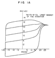
- the present invention enables a high degree of coercive force to be obtained, as compared with the sintered magnets. It is also seen that the sintered magnet of Comparative Example 1 which has the same composition as that of the upset magnet of the present invention fails to exhibit properties necessary for a permanent magnet because the Nd-rich grain boundary phases necessary for generating coercive force are not formed in the sintered magnet. It is also found from the recoil curves shown in Figs. 1A and 1B that the upset magnet of the present invention has a mechanism of generating coercive force which mechanism is of a pinning type different from that of the sintered magnet of Comparison Sample 2.
- Example 1 Each of the sample formed in Example 1 and the Comparison Sample 2 formed therein were continuously irradiated with ⁇ rays, and the magnetic characteristics thereof were measured after 100 hours, 500 hours, 1000 hours and 5000 hours had elapsed.
- the quenched-and-upset magnet of the present invention exhibits no deterioration in the magnetic characteristics thereof by irradiation of ⁇ rays.
- the quenched-and-upset magnet of the present invention exhibits no reduction in the coercive force by the irradiation of neutron rays.
Landscapes
- Chemical & Material Sciences (AREA)
- Crystallography & Structural Chemistry (AREA)
- Inorganic Chemistry (AREA)
- Engineering & Computer Science (AREA)
- Power Engineering (AREA)
- Hard Magnetic Materials (AREA)
- Particle Accelerators (AREA)
Claims (10)
- Dauermagnet zur Beschleunigung eines Korpuskularstrahls, mit einer Zusammensetzung der Formel RaFeRestCobBcGadMe in der R mindestens eines der Elemente Nd, Pr, Dy, Tb, Ho und Ce; und M mindestens eines der Elemente Al, Si, Nb, Ta, Ti, Zr, Hf und W bezeichnet und die Bedingungen 12 ≦ a ≦ 18; 0 ≦ b ≦ 30; 4 ≦ c ≦ 10; 0,01 ≦ d ≦ 3; und 0 ≦ e ≦ 2 (angegeben in Atomprozent) erfüllt sind, dadurch gekennzeichnet, daß der Dauermagnet ein Pinning-Magnet ist, der mit magnetischer Anisotropie versehene feinkristalline Körner enthält.
- Dauermagnet zur Beschleunigung eines Korpuskularstrahls nach Anspruch 1, wobei die mittlere Korngröße der feinkristallinen Körner 0,01 bis 0,5 µm beträgt.
- Dauermagnet zur Beschleunigung eines Korpuskularstrahls nach Anspruch 1 oder 2, wobei die magnetische Anisotropie durch plastische Verformung erzeugt ist.
- Dauermagnet zur Beschleunigung eines Korpuskularstrahls nach Anspruch 3, wobei das Verhältnis ho/h der plastischen Verformung 2 oder mehr beträgt.
- Dauermagnet zur Beschleunigung eines Korpuskularstrahls nach Anspruch 3, wobei ein der plastischen Verformung zu unterwerfender Feststoff nach einem Abschreckverfahren hergestellt ist.
- Dauermagnet zur Beschleunigung eines Korpuskularstrahls nach Anspruch 3, wobei die plastische Verformung Heißstauchen und/oder Warmextrudieren ist.
- Dauermagnet zur Beschleunigung eines Korpuskularstrahls nach Anspruch 6, wobei das Heißstrauchen in einem Temperaturbereich von 600 bis 800 °C und einer Dehnungsgeschwindigkeit von 1 x 10⁻⁴ bis 1 x 10⁻¹ s⁻¹ erfolgt.
- Dauermagnet zur Beschleunigung eines Korpuskularstrahls nach einem der Ansprüche 1 bis 7, wobei der Korpuskularstrahl ein radioaktiver Strahl, ein Elektronenstrahl oder ein Protonenstrahl ist.
- Dauermagnet zur Beschleunigung eines Korpuskularstrahls nach Anspruch 8, wobei der radioaktive Strahl ein Röntgenstrahl, ein γ-Strahl oder ein α-Strahl ist.
- Dauermagnet zur Beschleunigung eines Korpuskularstrahls nach einem der Ansprüche 1 bis 7, wobei der Korpuskularstrahl eine Mikrowelle, eine Ultrakurzwelle, eine Lichtwelle oder eine elektromagnetische Welle ist.
Applications Claiming Priority (2)
| Application Number | Priority Date | Filing Date | Title |
|---|---|---|---|
| JP62228883A JPS6472502A (en) | 1987-09-11 | 1987-09-11 | Permanent magnet for accelerating particle beam |
| JP228883/87 | 1987-09-11 |
Publications (2)
| Publication Number | Publication Date |
|---|---|
| EP0306981A1 EP0306981A1 (de) | 1989-03-15 |
| EP0306981B1 true EP0306981B1 (de) | 1993-04-28 |
Family
ID=16883354
Family Applications (1)
| Application Number | Title | Priority Date | Filing Date |
|---|---|---|---|
| EP88114799A Expired - Lifetime EP0306981B1 (de) | 1987-09-11 | 1988-09-09 | Dauermagnet zur Beschleunigung von korpuskularen Strahlen |
Country Status (5)
| Country | Link |
|---|---|
| US (1) | US5292380A (de) |
| EP (1) | EP0306981B1 (de) |
| JP (1) | JPS6472502A (de) |
| CA (1) | CA1318835C (de) |
| DE (1) | DE3880595T2 (de) |
Families Citing this family (11)
| Publication number | Priority date | Publication date | Assignee | Title |
|---|---|---|---|---|
| JPH01115104A (ja) * | 1987-10-28 | 1989-05-08 | Matsushita Electric Ind Co Ltd | 希土類磁石の製造法 |
| JPH04321202A (ja) * | 1991-04-19 | 1992-11-11 | Sanyo Special Steel Co Ltd | 異方性永久磁石の製造方法 |
| JP3311907B2 (ja) * | 1994-10-06 | 2002-08-05 | 増本 健 | 永久磁石材料、永久磁石及び永久磁石の製造方法 |
| US6004407A (en) * | 1995-09-22 | 1999-12-21 | Alps Electric Co., Ltd. | Hard magnetic materials and method of producing the same |
| KR100340592B1 (ko) * | 1999-08-11 | 2002-06-15 | 신현준 | 초미세립 희토류 영구자석 조성물 및 이를 이용한 영구자석 제조방법 |
| US6527874B2 (en) * | 2000-07-10 | 2003-03-04 | Sumitomo Special Metals Co., Ltd. | Rare earth magnet and method for making same |
| DE60143830D1 (de) * | 2000-08-11 | 2011-02-24 | Nissan Motor | Anisotroper Magnet und zugehöriges Herstellungsverfahren |
| US6979409B2 (en) * | 2003-02-06 | 2005-12-27 | Magnequench, Inc. | Highly quenchable Fe-based rare earth materials for ferrite replacement |
| US7570142B2 (en) * | 2003-02-27 | 2009-08-04 | Hitachi Metals, Ltd. | Permanent magnet for particle beam accelerator and magnetic field generator |
| JP5573444B2 (ja) * | 2010-07-14 | 2014-08-20 | トヨタ自動車株式会社 | 角形性に優れた希土類磁石の製造方法 |
| JP5472236B2 (ja) | 2011-08-23 | 2014-04-16 | トヨタ自動車株式会社 | 希土類磁石の製造方法、及び希土類磁石 |
Citations (1)
| Publication number | Priority date | Publication date | Assignee | Title |
|---|---|---|---|---|
| EP0216254A1 (de) * | 1985-09-10 | 1987-04-01 | Kabushiki Kaisha Toshiba | Dauermagnet |
Family Cites Families (17)
| Publication number | Priority date | Publication date | Assignee | Title |
|---|---|---|---|---|
| US4225339A (en) * | 1977-12-28 | 1980-09-30 | Tokyo Shibaura Denki Kabushiki Kaisha | Amorphous alloy of high magnetic permeability |
| US4402770A (en) * | 1981-10-23 | 1983-09-06 | The United States Of America As Represented By The Secretary Of The Navy | Hard magnetic alloys of a transition metal and lanthanide |
| CA1316375C (en) * | 1982-08-21 | 1993-04-20 | Masato Sagawa | Magnetic materials and permanent magnets |
| CA1315571C (en) * | 1982-08-21 | 1993-04-06 | Masato Sagawa | Magnetic materials and permanent magnets |
| JPS5946008A (ja) * | 1982-08-21 | 1984-03-15 | Sumitomo Special Metals Co Ltd | 永久磁石 |
| US4601875A (en) * | 1983-05-25 | 1986-07-22 | Sumitomo Special Metals Co., Ltd. | Process for producing magnetic materials |
| CA1236381A (en) * | 1983-08-04 | 1988-05-10 | Robert W. Lee | Iron-rare earth-boron permanent magnets by hot working |
| JPH06942B2 (ja) * | 1984-04-18 | 1994-01-05 | セイコーエプソン株式会社 | 希土類永久磁石 |
| JPH062930B2 (ja) * | 1984-05-14 | 1994-01-12 | セイコーエプソン株式会社 | 希土類永久磁石 |
| JPS60243247A (ja) * | 1984-05-15 | 1985-12-03 | Namiki Precision Jewel Co Ltd | 永久磁石合金 |
| CA1244322A (en) * | 1984-09-14 | 1988-11-08 | Robert W. Lee | Hot pressed permanent magnet having high and low coercivity regions |
| JPS61210862A (ja) * | 1985-03-13 | 1986-09-19 | Hitachi Metals Ltd | ボイスコイル型モ−タ− |
| JP2720027B2 (ja) * | 1985-04-19 | 1998-02-25 | 住友特殊金属株式会社 | 超低温用永久磁石材料 |
| JPS61266056A (ja) * | 1985-05-21 | 1986-11-25 | Seiko Epson Corp | リニアモ−タ |
| KR880000992A (ko) * | 1986-06-12 | 1988-03-30 | 와다리 스기이찌로오 | 영구자석 |
| US4827235A (en) * | 1986-07-18 | 1989-05-02 | Kabushiki Kaisha Toshiba | Magnetic field generator useful for a magnetic resonance imaging instrument |
| EP0258609B1 (de) * | 1986-07-23 | 1993-02-03 | Hitachi Metals, Ltd. | Dauermagnet mit guter thermischer Stabilität |
-
1987
- 1987-09-11 JP JP62228883A patent/JPS6472502A/ja active Pending
-
1988
- 1988-09-09 EP EP88114799A patent/EP0306981B1/de not_active Expired - Lifetime
- 1988-09-09 US US07/242,947 patent/US5292380A/en not_active Expired - Fee Related
- 1988-09-09 CA CA000576909A patent/CA1318835C/en not_active Expired - Fee Related
- 1988-09-09 DE DE8888114799T patent/DE3880595T2/de not_active Expired - Fee Related
Patent Citations (1)
| Publication number | Priority date | Publication date | Assignee | Title |
|---|---|---|---|---|
| EP0216254A1 (de) * | 1985-09-10 | 1987-04-01 | Kabushiki Kaisha Toshiba | Dauermagnet |
Non-Patent Citations (1)
| Title |
|---|
| Patent Abstracts of Japan, Vol. 2, No. 117, (E-498) (2564), April 11, 1987 * |
Also Published As
| Publication number | Publication date |
|---|---|
| US5292380A (en) | 1994-03-08 |
| EP0306981A1 (de) | 1989-03-15 |
| DE3880595T2 (de) | 1993-08-12 |
| DE3880595D1 (de) | 1993-06-03 |
| JPS6472502A (en) | 1989-03-17 |
| CA1318835C (en) | 1993-06-08 |
Similar Documents
| Publication | Publication Date | Title |
|---|---|---|
| EP0302395B1 (de) | Dauermagnete | |
| EP1705669B1 (de) | Seltenerd-Permanentmagnet | |
| EP0177371B1 (de) | Verfahren zur Herstellung eines Permanentmagneten | |
| JPH0531807B2 (de) | ||
| US4081297A (en) | RE-Co-Fe-transition metal permanent magnet and method of making it | |
| EP0306981B1 (de) | Dauermagnet zur Beschleunigung von korpuskularen Strahlen | |
| US4747874A (en) | Rare earth-iron-boron permanent magnets with enhanced coercivity | |
| JPH06275414A (ja) | Nd−Fe−B系永久磁石 | |
| EP0633582B1 (de) | Seltenerd magnetpulver und herstellungsverfahren | |
| JP2000114017A (ja) | 永久磁石材料および永久磁石 | |
| US4369075A (en) | Method of manufacturing permanent magnet alloys | |
| JPS6110209A (ja) | 永久磁石 | |
| EP0476606A2 (de) | Dauermagnetpulver | |
| JPH10106875A (ja) | 希土類磁石の製造方法 | |
| JP3118740B2 (ja) | 希土類磁石材料および希土類ボンド磁石 | |
| US4954186A (en) | Rear earth-iron-boron permanent magnets containing aluminum | |
| JP2000114016A (ja) | 永久磁石およびその製造方法 | |
| US5055129A (en) | Rare earth-iron-boron sintered magnets | |
| EP0539592B1 (de) | Magnetisches material | |
| US4981513A (en) | Mixed particulate composition for preparing rare earth-iron-boron sintered magnets | |
| US4878958A (en) | Method for preparing rare earth-iron-boron permanent magnets | |
| JP3209380B2 (ja) | 希土類焼結磁石およびその製造方法 | |
| JP2598558B2 (ja) | 永久磁石 | |
| EP0597582A1 (de) | Puder-Material für Seltenerd-Magnet | |
| US5015304A (en) | Rare earth-iron-boron sintered magnets |
Legal Events
| Date | Code | Title | Description |
|---|---|---|---|
| PUAI | Public reference made under article 153(3) epc to a published international application that has entered the european phase |
Free format text: ORIGINAL CODE: 0009012 |
|
| AK | Designated contracting states |
Kind code of ref document: A1 Designated state(s): DE FR GB |
|
| 17P | Request for examination filed |
Effective date: 19890427 |
|
| 17Q | First examination report despatched |
Effective date: 19920130 |
|
| GRAA | (expected) grant |
Free format text: ORIGINAL CODE: 0009210 |
|
| AK | Designated contracting states |
Kind code of ref document: B1 Designated state(s): DE FR GB |
|
| REF | Corresponds to: |
Ref document number: 3880595 Country of ref document: DE Date of ref document: 19930603 |
|
| ET | Fr: translation filed | ||
| PLBE | No opposition filed within time limit |
Free format text: ORIGINAL CODE: 0009261 |
|
| STAA | Information on the status of an ep patent application or granted ep patent |
Free format text: STATUS: NO OPPOSITION FILED WITHIN TIME LIMIT |
|
| 26N | No opposition filed | ||
| PGFP | Annual fee paid to national office [announced via postgrant information from national office to epo] |
Ref country code: GB Payment date: 19950829 Year of fee payment: 8 |
|
| PGFP | Annual fee paid to national office [announced via postgrant information from national office to epo] |
Ref country code: FR Payment date: 19950911 Year of fee payment: 8 |
|
| PGFP | Annual fee paid to national office [announced via postgrant information from national office to epo] |
Ref country code: DE Payment date: 19950918 Year of fee payment: 8 |
|
| PG25 | Lapsed in a contracting state [announced via postgrant information from national office to epo] |
Ref country code: GB Effective date: 19960909 |
|
| PG25 | Lapsed in a contracting state [announced via postgrant information from national office to epo] |
Ref country code: FR Effective date: 19960930 |
|
| GBPC | Gb: european patent ceased through non-payment of renewal fee |
Effective date: 19960909 |
|
| PG25 | Lapsed in a contracting state [announced via postgrant information from national office to epo] |
Ref country code: DE Effective date: 19970603 |
|
| REG | Reference to a national code |
Ref country code: FR Ref legal event code: ST |
|
| REG | Reference to a national code |
Ref country code: FR Ref legal event code: ST |