EP0306746A1 - Akkumulatorenbatterie - Google Patents
Akkumulatorenbatterie Download PDFInfo
- Publication number
- EP0306746A1 EP0306746A1 EP88113476A EP88113476A EP0306746A1 EP 0306746 A1 EP0306746 A1 EP 0306746A1 EP 88113476 A EP88113476 A EP 88113476A EP 88113476 A EP88113476 A EP 88113476A EP 0306746 A1 EP0306746 A1 EP 0306746A1
- Authority
- EP
- European Patent Office
- Prior art keywords
- cover plate
- cover
- block cover
- block
- cover part
- Prior art date
- Legal status (The legal status is an assumption and is not a legal conclusion. Google has not performed a legal analysis and makes no representation as to the accuracy of the status listed.)
- Granted
Links
Images
Classifications
-
- H—ELECTRICITY
- H01—ELECTRIC ELEMENTS
- H01M—PROCESSES OR MEANS, e.g. BATTERIES, FOR THE DIRECT CONVERSION OF CHEMICAL ENERGY INTO ELECTRICAL ENERGY
- H01M50/00—Constructional details or processes of manufacture of the non-active parts of electrochemical cells other than fuel cells, e.g. hybrid cells
- H01M50/10—Primary casings; Jackets or wrappings
- H01M50/147—Lids or covers
-
- H—ELECTRICITY
- H01—ELECTRIC ELEMENTS
- H01M—PROCESSES OR MEANS, e.g. BATTERIES, FOR THE DIRECT CONVERSION OF CHEMICAL ENERGY INTO ELECTRICAL ENERGY
- H01M50/00—Constructional details or processes of manufacture of the non-active parts of electrochemical cells other than fuel cells, e.g. hybrid cells
- H01M50/30—Arrangements for facilitating escape of gases
-
- Y—GENERAL TAGGING OF NEW TECHNOLOGICAL DEVELOPMENTS; GENERAL TAGGING OF CROSS-SECTIONAL TECHNOLOGIES SPANNING OVER SEVERAL SECTIONS OF THE IPC; TECHNICAL SUBJECTS COVERED BY FORMER USPC CROSS-REFERENCE ART COLLECTIONS [XRACs] AND DIGESTS
- Y02—TECHNOLOGIES OR APPLICATIONS FOR MITIGATION OR ADAPTATION AGAINST CLIMATE CHANGE
- Y02E—REDUCTION OF GREENHOUSE GAS [GHG] EMISSIONS, RELATED TO ENERGY GENERATION, TRANSMISSION OR DISTRIBUTION
- Y02E60/00—Enabling technologies; Technologies with a potential or indirect contribution to GHG emissions mitigation
- Y02E60/10—Energy storage using batteries
Definitions
- the invention relates to an accumulator battery, in particular a motor vehicle battery, the block cover of which has a hood-like part which extends over all cells and in which filling openings are optionally arranged, while the pole connections lie at opposite ends of a stepped block cover part.
- a battery with such a cover construction is known for example from GB-PS 1 548 129. It has proven to be very useful, particularly in the case of multi-cell accumulators which have a central degassing device. In this case, the gases generated during charging do not escape to the outside through ventilation openings in the sealing plugs, but are led to the outside through a channel running below the cover, with which all the gas spaces of the cells communicate.
- the central opening of this channel is usually on one of the narrow sides of the battery. It is often expanded or provided with a pipe extension, so that the battery gases loaded with acid mists can be released further away from corrosion-sensitive parts by pushing on a hose.
- lid types of the type mentioned at the outset were developed with a raised portion in the area of the filling openings because the additional space required by the degassing device was taken into account had to be worn and in many cases it proved to be very advantageous to integrate the channel system for the central degassing into this part of the cover by spraying appropriate walls or guide strips on the underside of the cover.
- the invention is therefore based on the object to design the lid of a battery according to the generic term mentioned in such a way that the top of the lid is formed by a smooth, easy-to-clean surface which extends over the entire battery outline, so that it covers all the outstanding parts and at the same time forms a Insulation against unintentional contact guaranteed.
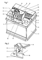
- a block cover 3 is welded onto the block box 2 of the lead battery 1 in FIG. 1 by conventional methods (for example mirror welding).
- the housing material is preferably made of polypropylene.
- the block cover is raised up to two smaller, opposing areas through which the pole connections 4 are passed, and has within this part the filling openings 5 arranged in a row of six, two of which are made visible by a tear of the cover plate.
- the closure plugs 6 of the filler openings are sunk so far that they are flush with the lid surface.
- the configuration of the battery according to the invention now consists in the fact that a flat plastic plate 8 covers the entire front part of the block box cover up to and including the sealing plug and also covers the exposed poles.
- the cover plate is hooked with its rear tapered edge into a suitable butt joint 9 on the rear part of the block cover, which is excluded from the roofing, and immovably fixed at the front to the raised block cover section 10, which protrudes like a bow to the front center of the block box. Details of this attachment are shown in Figure 2.
- the cover plate according to the invention is thus supported on the one hand by the larger part of the raised block cover extending to the butt joint 9 and on the other hand is flush with the remaining part behind the butt joint.
- the cover plate which is releasably attached to the block cover, only has to be removed for refilling the acid and for general maintenance work.
- the pole connections are separately accessible by folding up the protective front corner regions 11 of the plate.
- the cover plate in the cover plate shortly behind the transition stage from the lower to the higher part of the block cover from both narrow sides in the longitudinal direction of the battery cut-in slots 12, the length of the slots corresponding approximately to the smallest width of one of the lower block cover areas.
- the cover plate is notched on the underside. Due to the lower material thickness of the plate there, the notches 13 represent flexible hinges.
- the opposite ends 11 thereby have the function of flaps.
- the top of the cover plate runs out into a narrow ridge 14 projecting over the slot, which has a counterpart 15, but with an inverse bevel, on each of the flaps.
- the two ridges overlap in such a way that the ridge 14 overlaps the ridge 15 of the flap and thus holds the flap on the raised part of the block cover, shortly before the gradation to the lower area around the poles.
- the flaps can only be opened and closed in this way only against the force of a residual elasticity inherent in the ridges, which must be used to overcome the overlap.
- a nose 16 is injection molded under the front part of the cover plate 8, which rests on the bay-like protruding block cover section 10 after the final assembly (a second nose arranged symmetrically to this is not shown).
- a matching opening 17 in the cover section 10 correlates with each nose and receives the nose when the cover plate is placed on the block cover.
- Burr-like projections 18 are formed from the side walls of the openings, which exert a frictional contact with the lugs and thereby hold the cover plate on the block cover even when the battery is strongly shaken.
Landscapes
- Chemical & Material Sciences (AREA)
- Chemical Kinetics & Catalysis (AREA)
- Electrochemistry (AREA)
- General Chemical & Material Sciences (AREA)
- Battery Mounting, Suspending (AREA)
- Connection Of Batteries Or Terminals (AREA)
- Sealing Battery Cases Or Jackets (AREA)
- Gas Exhaust Devices For Batteries (AREA)
- Casings For Electric Apparatus (AREA)
Abstract
Description
- Die Erfindung betrifft eine Akkumulatorenbatterie, insbesondere Kraftfahrzeugbatterie, deren Blockdeckel eine sich über alle Zellen erstreckenden haubenförmig erhöhten Teil besitzt, in welchem gegebenenfalls Einfüllöffnungen angeordnet sind, während die Polanschlüsse an gegenüberliegenden Enden eines abgesetzten Blockdeckelteils liegen.
- Eine Batterie mit einer derartigen Deckelkonstruktion ist beispielsweise aus der GB-PS 1 548 129 bekannt. Sie hat sich insbesondere bei solchen mehrzelligen Akkumulatoren als sehr zweckmäßig erwiesen, die eine zentrale Entgasungseinrichtung besitzen. In diesem Fall gelangen die beim Laden entstehenden Gase nicht durch Belüftungsöffnungen in den Verschlußstöpseln ins Freie, sondern werden durch einen unterhalb des Deckels verlaufenden Kanal, mit dem alle Gasräume der Zellen kommunizieren, nach außen geführt. Die zentrale Öffnung dieses Kanals befindet sich meist an einer der Schmalseiten der Batterie. Häufig ist sie ausgeweitet oder mit einem Rohransatz versehen, so daß durch Aufschieben eines Schlauches die mit Säurenebeln beladenen Akkumulatorgase von korrosionsempfindlichen Teilen weiter entfernt in Freiheit gesetzt werden können.
- Durch die Einführung eines zentralen Entgasungssystems, bei dem ein Kanal alle Einfüllöffnungen verbindet und entweder in Reihe mit diesen oder parallel zu denselben verläuft, wurden Deckelformen er eingangs genannten Art mit einem haubenförmig erhöhten Teil im Bereich der Einfüllöffnungen entwickelt, weil dem zusätzlichen Raumbedarf der Entgasungseinrichtung Rechnung getragen werden mußte und es sich in vielen Fällen als sehr vorteilhaft erwies, das Kanalsystem für die zentrale Entgasung in diesen Teil des Deckels durch Anspritzen entsprechender Wände oder Führungsleisten an die Deckelunterseite zu integrieren.
- Während durch diese bekannte Ausbildung des Batteriedeckels, nachdem die Einfüllöffnungen noch mit dichtschließenden Verschlußstöpseln versehen worden sind, Beschädigungen am Fahrzeug infolge austretender Elektrolytteilchen wirksam verhindert werden, sind die an gegenüberliegenden abgesetzten Teilen des Deckels angeordneten Polanschlüsse gegen Verschmutzung durch Säure, die bei unachtsamem Füllen von den höher gelegenen Einfüllöffnungen leicht zu diesen hinfließen kann, nicht geschützt. Da ferner der erhöhte Teil des Batteriedeckels sich mit dem überwiegenden Teil des Deckelumrisses deckt und eine zusammenhängende Fläche zur vorübergehenden Ablage von Gegenständen, z.B. Werkzeugen, anbietet, besteht für die freiliegenden, etwa gleichhohen Polköpfe die Gefahr, daß sie zur Unterstützung der abgelegten Gegenstände mit herangezogen werden, wobei sich Kurzschlüsse ergeben können.
- Der Erfindung liegt daher die Aufgabe zugrunde, die Verdeckelung einer Batterie nach dem eingangs genannten Gattungsbegriff so zu gestalten, daß die Deckeloberseite von einer glatten, gut zu reinigenden und über den gesamten Batterieumriß ausgedehnten Oberfläche gebildet ist, daß sie sämtliche herausragenden Teile überdeckt und gleichzeitig eine Isolation gegen unbeabsichtigtes Berühren gewährleistet.
- Die Aufgabe wird erfindungsgemäß mit den im kennzeichnenden Teil von Anspruch 1 angegebenen Mitteln gelöst.
- Anhand zweier Figurendarstellungen werden Einzelheiten, Merkmale und Vorteile der Erfindung verdeutlicht.
- Figur 1 zeigt eine 6-zellige Bleibatterie (12V, 36 Ah) gemäß Neuerung
- Figur 2 zeigt die Arretierung der erfindungsgemäßen Abdeckplatte am Blockkastendeckel im Detail (eingekreister Ausschnitt in der Figur 1).
- Auf den Blockkasten 2 der Bleibatterie 1 in Figur 1 ist ein Blockdeckel 3 nach üblichen Verfahren (z.B. Spiegelschweißen) aufgeschweißt. Das Gehäusematerial besteht vorzugsweise aus Polypropylen.
- Der Blockdeckel ist bis auf zwei kleinere, einander gegenüberliegende Bereiche, durch welche die Polanschlüsse 4 hindurchgeführt sind, haubenförmig erhöht und weist innerhalb dieses Teils die in einer Sechserreihe angeordneten Einfüllöffnungen 5 auf, von denen zwei durch einen Aufriß der Abdeckplatte sichtbar gemacht sind. Die Verschlußstöpsel 6 der Einfüllöffnungen sind so weit versenkt, daß sie mit der Deckeloberfläche bündig abschließen.
- An der rechten Schmalseite des Blockdeckels befindet sich ferner die Austrittsöffnung 7 eines Entgasungskanals.
- Die erfindungsgemäße Ausgestaltung der Batterie besteht nun darin, daß eine flache Kunststoffplatte 8 den gesamten vorderen Teil des Blockkastendeckels bis einschließlich der Verschlußstöpsel abdeckt und dabei auch die freiliegenden Pole überdacht. Die Abdeckplatte ist mit ihrer hinteren zugespitzten Kante in eine passende Stoßfuge 9 am hinteren, von der Überdachung ausgenommenen Teil des Blockdeckels eingehakt und vorne an dem erkerartig bis zur vorderen Mitte des Blockkastens vorspringenden erhöhten Blockdeckelabschnitt 10 unverrückbar fixiert. Einzelheiten dieser Befestigung sind in Figur 2 dargestellt.
- Die erfindungsgemäße Abdeckplatte ist damit einerseits von dem größeren, sich bis zur Stoßfuge 9 erstreckenden Teil des erhöhten Blockdeckels abgestützt und schließt mit dem hinter der Stoßfuge befindlichen Restteil andererseits bündig ab. Auf diese Weise ergibt sich eine Verdeckelung mit einer dem Batterieumriß angepaßten, absolut ebenen Abdeckfläche, die nicht nur unempfindlich gegen Verschmutzung bzw. leicht sauber zu halten ist, sondern sich auch für dekorative Beschriftungen, Anbringung von Firmenzeichen, Typen-Nummern oder dergl. gut eignet.
- Als ein weiterer Vorteil der Erfindung kommt hinzu, daß die lösbar am Blockdeckel befestigte Abdeckplatte nur zum Nachfüllen der Säure und bei allgemeinen Wartungsarbeiten abgenommen werden muß. Dagegen sind die Polanschlüsse durch Hochklappen der diese schützenden vorderen Eckbereiche 11 der Platte gesondert zugänglich. Zu diesem Zweck sind in die Abdeckplatte kurz hinter der Übergangsstufe vom niederen zum höheren Teil des Blockdeckels von beiden Schmalseiten her in Längsrichtung der Batterie Trennschlitze 12 eingearbeitet, wobei die Länge der Schlitze etwa der kleinsten Breite eines der niederen Blockdeckelbereiche entspricht. In senkrechter Richtung zu den Schlitzen, entlang einer Linie, die von den Enden der Schlitze bis zur Vorderkante der Abdeckplatte verläuft, ist die Abdeckplatte auf der Unterseite gekerbt. Infolge der dort geringeren Materialstärke der Platte stellen die Kerben 13 flexible Scharniere dar. Die gegenüberliegenden Enden 11 erhalten dadurch die Funktion von Klappen. Am vorderen Ende eines Schlitzes läuft die Oberseite der Abdeckplatte zu einem schmalen, über den Schlitz vorspringenden Grat 14 aus, welcher ein Gegenstück 15, jedoch mit invers gerichteter Abschrägung, an jeder der Klappen besitzt. In der Schließposition der Klappen überlappen sich die beiden Grate derart, daß der Grat 14 den Grat 15 der Klappe übergreift und die Klappe damit am erhöhten Teil des Blockdeckels, kurz vor der Abstufung zu dem niederen Bereich um die Pole, festhält. Die Klappen lassen sich auf diese Weise stets nur gegen die Kraft einer den Graten innewohnenden Restelastizität, die zum Überwin den der Überlappung aufgewendet werden muß, öffnen und schließen.
- Nach Figur 2 ist unter dem vorderen Teil der Abdeckplatte 8, welcher nach der Fertigmontage dem erkerartig vorspringenden Blockdeckelabschnitt 10 aufliegt, eine Nase 16 angespritzt (eine symmetrisch zu dieser angeordnete zweite Nase ist nicht dargestellt). Mit jeder Nase korreliert eine passende Öffnung 17 in dem Deckelabschnitt 10, welche die Nase beim Aufsetzen der Abdeckplatte auf den Blockdeckel aufnimmt. Aus den Seitenwänden der Öffnungen sind gratähnliche Vorsprünge 18 ausgeformt, die eine Reibungskontakt mit den Nasen ausüben und die Abdeckplatte dadurch auch bei starken Ershütterungen der Batterie am Blockdeckel festhalten.
Claims (4)
Priority Applications (1)
| Application Number | Priority Date | Filing Date | Title |
|---|---|---|---|
| AT88113476T ATE69669T1 (de) | 1987-09-03 | 1988-08-19 | Akkumulatorenbatterie. |
Applications Claiming Priority (2)
| Application Number | Priority Date | Filing Date | Title |
|---|---|---|---|
| DE3729523 | 1987-09-03 | ||
| DE19873729523 DE3729523A1 (de) | 1987-09-03 | 1987-09-03 | Akkumulatorenbatterie |
Publications (2)
| Publication Number | Publication Date |
|---|---|
| EP0306746A1 true EP0306746A1 (de) | 1989-03-15 |
| EP0306746B1 EP0306746B1 (de) | 1991-11-21 |
Family
ID=6335172
Family Applications (1)
| Application Number | Title | Priority Date | Filing Date |
|---|---|---|---|
| EP88113476A Expired - Lifetime EP0306746B1 (de) | 1987-09-03 | 1988-08-19 | Akkumulatorenbatterie |
Country Status (4)
| Country | Link |
|---|---|
| EP (1) | EP0306746B1 (de) |
| AT (1) | ATE69669T1 (de) |
| DE (2) | DE3729523A1 (de) |
| ES (1) | ES2027355T3 (de) |
Cited By (2)
| Publication number | Priority date | Publication date | Assignee | Title |
|---|---|---|---|---|
| EP0606850A3 (en) * | 1993-01-12 | 1997-01-29 | Hagen Batterie Ag | Battery with detachable cover plate covering the terminals. |
| EP0915525A1 (de) * | 1997-11-04 | 1999-05-12 | Olimpio Stocchiero | Polabdeckung auf einen Batteriedeckel |
Families Citing this family (2)
| Publication number | Priority date | Publication date | Assignee | Title |
|---|---|---|---|---|
| JP2001332235A (ja) * | 2000-05-25 | 2001-11-30 | Yazaki Corp | バッテリカバー |
| DE102021118631A1 (de) | 2021-07-19 | 2023-01-19 | Webasto SE | Batteriegehäuse und Verfahren zur Herstellung eines Batteriegehäuses |
Citations (2)
| Publication number | Priority date | Publication date | Assignee | Title |
|---|---|---|---|---|
| GB1548129A (en) * | 1978-02-17 | 1979-07-04 | Chloride Group Ltd | Electric storage battery lids |
| DE3544003A1 (de) * | 1985-12-13 | 1987-06-19 | Bosch Gmbh Robert | Batteriedeckel |
-
1987
- 1987-09-03 DE DE19873729523 patent/DE3729523A1/de not_active Withdrawn
-
1988
- 1988-08-19 ES ES198888113476T patent/ES2027355T3/es not_active Expired - Lifetime
- 1988-08-19 EP EP88113476A patent/EP0306746B1/de not_active Expired - Lifetime
- 1988-08-19 AT AT88113476T patent/ATE69669T1/de not_active IP Right Cessation
- 1988-08-19 DE DE8888113476T patent/DE3866316D1/de not_active Expired - Lifetime
Patent Citations (2)
| Publication number | Priority date | Publication date | Assignee | Title |
|---|---|---|---|---|
| GB1548129A (en) * | 1978-02-17 | 1979-07-04 | Chloride Group Ltd | Electric storage battery lids |
| DE3544003A1 (de) * | 1985-12-13 | 1987-06-19 | Bosch Gmbh Robert | Batteriedeckel |
Cited By (3)
| Publication number | Priority date | Publication date | Assignee | Title |
|---|---|---|---|---|
| EP0606850A3 (en) * | 1993-01-12 | 1997-01-29 | Hagen Batterie Ag | Battery with detachable cover plate covering the terminals. |
| EP0915525A1 (de) * | 1997-11-04 | 1999-05-12 | Olimpio Stocchiero | Polabdeckung auf einen Batteriedeckel |
| US6124055A (en) * | 1997-11-04 | 2000-09-26 | Stocchiero; Olimpio | Cover for polar element for the lid of a battery |
Also Published As
| Publication number | Publication date |
|---|---|
| DE3729523A1 (de) | 1989-03-16 |
| DE3866316D1 (de) | 1992-01-02 |
| EP0306746B1 (de) | 1991-11-21 |
| ATE69669T1 (de) | 1991-12-15 |
| ES2027355T3 (es) | 1992-06-01 |
Similar Documents
| Publication | Publication Date | Title |
|---|---|---|
| DE2241540A1 (de) | Schutzbehaelter fuer eine bandkassette mit zwei naben | |
| EP0306746B1 (de) | Akkumulatorenbatterie | |
| DE2854333C2 (de) | Behälterdeckel mit einem Kunstharz-Verschlußglied für die Ausgabeöffnung | |
| DE8500180U1 (de) | Kasten oder Koffer für Computer | |
| DE7833886U1 (de) | Einbaugehäuse aus Kunststoff | |
| DE19635712A1 (de) | Deckel zum Verschließen von Kästen | |
| EP0330833A2 (de) | Schachtel für einen Flüssigkeitsbehälter | |
| DD131235B1 (de) | Werkzeug-oder geraetekasten mit herausschwenkbaren eins | |
| DE69707217T2 (de) | Elektronische Verbindungsleiste zum Befestigung an einem Träger, insbesondere für autonome Notbeleuchtungsanlage | |
| EP0045001B1 (de) | Steckdosenanordnung mit Fehlerstromschutzschalter | |
| DE2615457A1 (de) | Magazin | |
| DE3326906C2 (de) | Weidezaungerät | |
| DE19717279B4 (de) | Einheit aus zwei miteinander in Verbindung stehenden Behältnissen | |
| DE19546693C1 (de) | Aufnahmetüte für Raucher- und/oder Kaugummiabfälle | |
| DE2507620A1 (de) | Kassettenbehaelter | |
| DE2914415A1 (de) | Cassettenbehaelter | |
| DE29607464U1 (de) | Verpackung für Elektrogeräte | |
| DE202006010818U1 (de) | Gerätebecher | |
| EP0822618B1 (de) | Gehäuse für Faltstecker mit Deckelauflageplattform | |
| DE3631203A1 (de) | Trockenelementebatterie mit sauerstoffdepolarisation | |
| DE8331193U1 (de) | Leuchte, insbesondere handleuchte | |
| DE2041026A1 (de) | Schachtelartige Verpackung,insbesondere fuer Zigaretten | |
| DE202013102770U1 (de) | Aufsatzelement für eine stapelbare Systembox | |
| EP0971466A1 (de) | Einbaudose zur Verwendung in Kabelkanälen, wie Brüstungskanälen | |
| DE2741414A1 (de) | Sicherungsunterteil |
Legal Events
| Date | Code | Title | Description |
|---|---|---|---|
| PUAI | Public reference made under article 153(3) epc to a published international application that has entered the european phase |
Free format text: ORIGINAL CODE: 0009012 |
|
| AK | Designated contracting states |
Kind code of ref document: A1 Designated state(s): AT BE DE ES FR GB IT NL SE |
|
| 17P | Request for examination filed |
Effective date: 19890222 |
|
| 17Q | First examination report despatched |
Effective date: 19910301 |
|
| GRAA | (expected) grant |
Free format text: ORIGINAL CODE: 0009210 |
|
| AK | Designated contracting states |
Kind code of ref document: B1 Designated state(s): AT BE DE ES FR GB IT NL SE |
|
| REF | Corresponds to: |
Ref document number: 69669 Country of ref document: AT Date of ref document: 19911215 Kind code of ref document: T |
|
| ITF | It: translation for a ep patent filed | ||
| GBT | Gb: translation of ep patent filed (gb section 77(6)(a)/1977) | ||
| REF | Corresponds to: |
Ref document number: 3866316 Country of ref document: DE Date of ref document: 19920102 |
|
| ET | Fr: translation filed | ||
| PLBE | No opposition filed within time limit |
Free format text: ORIGINAL CODE: 0009261 |
|
| STAA | Information on the status of an ep patent application or granted ep patent |
Free format text: STATUS: NO OPPOSITION FILED WITHIN TIME LIMIT |
|
| 26N | No opposition filed | ||
| REG | Reference to a national code |
Ref country code: GB Ref legal event code: 732E |
|
| REG | Reference to a national code |
Ref country code: FR Ref legal event code: TP |
|
| REG | Reference to a national code |
Ref country code: ES Ref legal event code: PC2A Owner name: VB AUTOBATTERIE GMBH. |
|
| NLS | Nl: assignments of ep-patents |
Owner name: VB AUTOBATTERIE GMBH TE HANNOVER, BONDSREPUBLIEK D |
|
| EAL | Se: european patent in force in sweden |
Ref document number: 88113476.1 |
|
| PGFP | Annual fee paid to national office [announced via postgrant information from national office to epo] |
Ref country code: BE Payment date: 20010606 Year of fee payment: 14 |
|
| PGFP | Annual fee paid to national office [announced via postgrant information from national office to epo] |
Ref country code: ES Payment date: 20010801 Year of fee payment: 14 |
|
| PGFP | Annual fee paid to national office [announced via postgrant information from national office to epo] |
Ref country code: DE Payment date: 20010803 Year of fee payment: 14 |
|
| PGFP | Annual fee paid to national office [announced via postgrant information from national office to epo] |
Ref country code: SE Payment date: 20010806 Year of fee payment: 14 |
|
| PGFP | Annual fee paid to national office [announced via postgrant information from national office to epo] |
Ref country code: GB Payment date: 20010815 Year of fee payment: 14 |
|
| PGFP | Annual fee paid to national office [announced via postgrant information from national office to epo] |
Ref country code: AT Payment date: 20010824 Year of fee payment: 14 |
|
| PGFP | Annual fee paid to national office [announced via postgrant information from national office to epo] |
Ref country code: FR Payment date: 20010830 Year of fee payment: 14 |
|
| PGFP | Annual fee paid to national office [announced via postgrant information from national office to epo] |
Ref country code: NL Payment date: 20010831 Year of fee payment: 14 |
|
| REG | Reference to a national code |
Ref country code: GB Ref legal event code: IF02 |
|
| PG25 | Lapsed in a contracting state [announced via postgrant information from national office to epo] |
Ref country code: GB Free format text: LAPSE BECAUSE OF NON-PAYMENT OF DUE FEES Effective date: 20020819 Ref country code: AT Free format text: LAPSE BECAUSE OF NON-PAYMENT OF DUE FEES Effective date: 20020819 |
|
| PG25 | Lapsed in a contracting state [announced via postgrant information from national office to epo] |
Ref country code: SE Free format text: LAPSE BECAUSE OF NON-PAYMENT OF DUE FEES Effective date: 20020820 Ref country code: ES Free format text: LAPSE BECAUSE OF NON-PAYMENT OF DUE FEES Effective date: 20020820 |
|
| PG25 | Lapsed in a contracting state [announced via postgrant information from national office to epo] |
Ref country code: BE Free format text: LAPSE BECAUSE OF NON-PAYMENT OF DUE FEES Effective date: 20020831 |
|
| BERE | Be: lapsed |
Owner name: *VB AUTOBATTERIE G.M.B.H. Effective date: 20020831 |
|
| PG25 | Lapsed in a contracting state [announced via postgrant information from national office to epo] |
Ref country code: NL Free format text: LAPSE BECAUSE OF NON-PAYMENT OF DUE FEES Effective date: 20030301 Ref country code: DE Free format text: LAPSE BECAUSE OF NON-PAYMENT OF DUE FEES Effective date: 20030301 |
|
| EUG | Se: european patent has lapsed | ||
| GBPC | Gb: european patent ceased through non-payment of renewal fee |
Effective date: 20020819 |
|
| PG25 | Lapsed in a contracting state [announced via postgrant information from national office to epo] |
Ref country code: FR Free format text: LAPSE BECAUSE OF NON-PAYMENT OF DUE FEES Effective date: 20030430 |
|
| NLV4 | Nl: lapsed or anulled due to non-payment of the annual fee |
Effective date: 20030301 |
|
| REG | Reference to a national code |
Ref country code: FR Ref legal event code: ST |
|
| REG | Reference to a national code |
Ref country code: ES Ref legal event code: FD2A Effective date: 20030912 |
|
| PG25 | Lapsed in a contracting state [announced via postgrant information from national office to epo] |
Ref country code: IT Free format text: LAPSE BECAUSE OF NON-PAYMENT OF DUE FEES;WARNING: LAPSES OF ITALIAN PATENTS WITH EFFECTIVE DATE BEFORE 2007 MAY HAVE OCCURRED AT ANY TIME BEFORE 2007. THE CORRECT EFFECTIVE DATE MAY BE DIFFERENT FROM THE ONE RECORDED. Effective date: 20050819 |