EP0306049A2 - Vorrichtung zur Partikel-Verbrennung in der Abgasanlage eines Dieselmotors - Google Patents
Vorrichtung zur Partikel-Verbrennung in der Abgasanlage eines Dieselmotors Download PDFInfo
- Publication number
- EP0306049A2 EP0306049A2 EP88114384A EP88114384A EP0306049A2 EP 0306049 A2 EP0306049 A2 EP 0306049A2 EP 88114384 A EP88114384 A EP 88114384A EP 88114384 A EP88114384 A EP 88114384A EP 0306049 A2 EP0306049 A2 EP 0306049A2
- Authority
- EP
- European Patent Office
- Prior art keywords
- wire mesh
- particles
- hollow cylinder
- flow channel
- flow
- Prior art date
- Legal status (The legal status is an assumption and is not a legal conclusion. Google has not performed a legal analysis and makes no representation as to the accuracy of the status listed.)
- Withdrawn
Links
Images

Classifications
-
- F—MECHANICAL ENGINEERING; LIGHTING; HEATING; WEAPONS; BLASTING
- F01—MACHINES OR ENGINES IN GENERAL; ENGINE PLANTS IN GENERAL; STEAM ENGINES
- F01N—GAS-FLOW SILENCERS OR EXHAUST APPARATUS FOR MACHINES OR ENGINES IN GENERAL; GAS-FLOW SILENCERS OR EXHAUST APPARATUS FOR INTERNAL-COMBUSTION ENGINES
- F01N3/00—Exhaust or silencing apparatus having means for purifying, rendering innocuous, or otherwise treating exhaust
- F01N3/02—Exhaust or silencing apparatus having means for purifying, rendering innocuous, or otherwise treating exhaust for cooling, or for removing solid constituents of, exhaust
- F01N3/021—Exhaust or silencing apparatus having means for purifying, rendering innocuous, or otherwise treating exhaust for cooling, or for removing solid constituents of, exhaust by means of filters
- F01N3/033—Exhaust or silencing apparatus having means for purifying, rendering innocuous, or otherwise treating exhaust for cooling, or for removing solid constituents of, exhaust by means of filters in combination with other devices
- F01N3/035—Exhaust or silencing apparatus having means for purifying, rendering innocuous, or otherwise treating exhaust for cooling, or for removing solid constituents of, exhaust by means of filters in combination with other devices with catalytic reactors
-
- F—MECHANICAL ENGINEERING; LIGHTING; HEATING; WEAPONS; BLASTING
- F01—MACHINES OR ENGINES IN GENERAL; ENGINE PLANTS IN GENERAL; STEAM ENGINES
- F01N—GAS-FLOW SILENCERS OR EXHAUST APPARATUS FOR MACHINES OR ENGINES IN GENERAL; GAS-FLOW SILENCERS OR EXHAUST APPARATUS FOR INTERNAL-COMBUSTION ENGINES
- F01N13/00—Exhaust or silencing apparatus characterised by constructional features
- F01N13/009—Exhaust or silencing apparatus characterised by constructional features having two or more separate purifying devices arranged in series
-
- F—MECHANICAL ENGINEERING; LIGHTING; HEATING; WEAPONS; BLASTING
- F01—MACHINES OR ENGINES IN GENERAL; ENGINE PLANTS IN GENERAL; STEAM ENGINES
- F01N—GAS-FLOW SILENCERS OR EXHAUST APPARATUS FOR MACHINES OR ENGINES IN GENERAL; GAS-FLOW SILENCERS OR EXHAUST APPARATUS FOR INTERNAL-COMBUSTION ENGINES
- F01N3/00—Exhaust or silencing apparatus having means for purifying, rendering innocuous, or otherwise treating exhaust
- F01N3/02—Exhaust or silencing apparatus having means for purifying, rendering innocuous, or otherwise treating exhaust for cooling, or for removing solid constituents of, exhaust
- F01N3/021—Exhaust or silencing apparatus having means for purifying, rendering innocuous, or otherwise treating exhaust for cooling, or for removing solid constituents of, exhaust by means of filters
- F01N3/0217—Exhaust or silencing apparatus having means for purifying, rendering innocuous, or otherwise treating exhaust for cooling, or for removing solid constituents of, exhaust by means of filters the filtering elements having the form of hollow cylindrical bodies
-
- F—MECHANICAL ENGINEERING; LIGHTING; HEATING; WEAPONS; BLASTING
- F01—MACHINES OR ENGINES IN GENERAL; ENGINE PLANTS IN GENERAL; STEAM ENGINES
- F01N—GAS-FLOW SILENCERS OR EXHAUST APPARATUS FOR MACHINES OR ENGINES IN GENERAL; GAS-FLOW SILENCERS OR EXHAUST APPARATUS FOR INTERNAL-COMBUSTION ENGINES
- F01N3/00—Exhaust or silencing apparatus having means for purifying, rendering innocuous, or otherwise treating exhaust
- F01N3/02—Exhaust or silencing apparatus having means for purifying, rendering innocuous, or otherwise treating exhaust for cooling, or for removing solid constituents of, exhaust
- F01N3/021—Exhaust or silencing apparatus having means for purifying, rendering innocuous, or otherwise treating exhaust for cooling, or for removing solid constituents of, exhaust by means of filters
- F01N3/023—Exhaust or silencing apparatus having means for purifying, rendering innocuous, or otherwise treating exhaust for cooling, or for removing solid constituents of, exhaust by means of filters using means for regenerating the filters, e.g. by burning trapped particles
-
- F—MECHANICAL ENGINEERING; LIGHTING; HEATING; WEAPONS; BLASTING
- F01—MACHINES OR ENGINES IN GENERAL; ENGINE PLANTS IN GENERAL; STEAM ENGINES
- F01N—GAS-FLOW SILENCERS OR EXHAUST APPARATUS FOR MACHINES OR ENGINES IN GENERAL; GAS-FLOW SILENCERS OR EXHAUST APPARATUS FOR INTERNAL-COMBUSTION ENGINES
- F01N3/00—Exhaust or silencing apparatus having means for purifying, rendering innocuous, or otherwise treating exhaust
- F01N3/08—Exhaust or silencing apparatus having means for purifying, rendering innocuous, or otherwise treating exhaust for rendering innocuous
- F01N3/10—Exhaust or silencing apparatus having means for purifying, rendering innocuous, or otherwise treating exhaust for rendering innocuous by thermal or catalytic conversion of noxious components of exhaust
- F01N3/24—Exhaust or silencing apparatus having means for purifying, rendering innocuous, or otherwise treating exhaust for rendering innocuous by thermal or catalytic conversion of noxious components of exhaust characterised by constructional aspects of converting apparatus
- F01N3/28—Construction of catalytic reactors
- F01N3/2882—Catalytic reactors combined or associated with other devices, e.g. exhaust silencers or other exhaust purification devices
-
- F—MECHANICAL ENGINEERING; LIGHTING; HEATING; WEAPONS; BLASTING
- F01—MACHINES OR ENGINES IN GENERAL; ENGINE PLANTS IN GENERAL; STEAM ENGINES
- F01N—GAS-FLOW SILENCERS OR EXHAUST APPARATUS FOR MACHINES OR ENGINES IN GENERAL; GAS-FLOW SILENCERS OR EXHAUST APPARATUS FOR INTERNAL-COMBUSTION ENGINES
- F01N2250/00—Combinations of different methods of purification
- F01N2250/02—Combinations of different methods of purification filtering and catalytic conversion
-
- F—MECHANICAL ENGINEERING; LIGHTING; HEATING; WEAPONS; BLASTING
- F02—COMBUSTION ENGINES; HOT-GAS OR COMBUSTION-PRODUCT ENGINE PLANTS
- F02B—INTERNAL-COMBUSTION PISTON ENGINES; COMBUSTION ENGINES IN GENERAL
- F02B3/00—Engines characterised by air compression and subsequent fuel addition
- F02B3/06—Engines characterised by air compression and subsequent fuel addition with compression ignition
Definitions
- the invention relates to a device for soot particle combustion in the exhaust system of a diesel engine.
- the exhaust gases from diesel engines contain, in addition to the gaseous pollutants, such as carbon monoxide, hydrocarbon compounds and nitrogen oxides, also organic and inorganic particles. These particles consist essentially of carbon, condensable and carbon-bonded hydrocarbon compounds, sulfur compounds and other particles. For reasons of environmental protection, attempts are made to retain the highest possible proportion of these particles contained in the exhaust gas stream. For this purpose, filter systems are used, in which the particles are to accumulate up to a certain degree of loading and which are then separated by a so-called. Filter regeneration be brought back into a condition necessary for the correct operation of the engine.
- the gaseous pollutants such as carbon monoxide, hydrocarbon compounds and nitrogen oxides
- organic and inorganic particles consist essentially of carbon, condensable and carbon-bonded hydrocarbon compounds, sulfur compounds and other particles.
- filter systems are used, in which the particles are to accumulate up to a certain degree of loading and which are then separated by a so-called. Filter regeneration be brought back into a condition necessary for the correct operation of the engine.
- This regeneration must be carried out at the latest when the permissible exhaust gas back pressure is reached.
- several methods are known in which the oxidizable particle load is burned. If the exhaust gases are at a sufficiently high temperature when they exit the engine, this can be done by self-ignition. Another measure is to carry out additional external heating or spark ignition. Particle combustion can also be achieved by lowering the autoignition temperature by catalysis or by adding Oxidation promoting agents take place. This measure is carried out in view of the fact that the ignition temperature of the soot itself is relatively high. Under favorable conditions, however, the catalytic coating already leads to burning at temperatures below this range, so that an external ignition aid can be dispensed with.
- the temperature of the exhaust gases is still below the ignition temperature.
- the invention has for its object to provide a device for soot particle combustion of the type mentioned, with which the temperature of the particles is increased in a simple manner.
- a basic idea of the invention is to be seen in the fact that the kinetic energy of the particles emerging from the engine at high speed is converted into thermal energy by friction, which leads to an increase in the particle temperature. Depending on the flow rate, it is possible to increase the particle temperature up to 80 ° C.
- the invention has the advantage that soot particles are burned by self-ignition even if the exhaust gas temperature is below the ignition point when exiting the engine.
- Another advantage can be seen in the fact that soot particles accumulate in the wire knit in the starting phase meln, and that these are subsequently burned when the wire mesh is heated sufficiently by the frictional heat.
- Another advantage is that a front silencer can be omitted. An additional fuel consumption or a loss of performance is avoided.
- the radial guide device consists of a spiral housing.
- the radial guide device can also be expedient for the radial guide device to consist of guide vanes which are oriented tangentially or radially.
- the guide device consists of a thick-walled hollow cylinder made of catalytically coated material with a plurality of through openings, that this hollow cylinder is wrapped with the wire mesh, and that an annular space is present around the wire mesh for the circulation of the particles.
- this hollow cylinder can also be formed from a foam ceramic.
- the wire mesh may be surrounded with a perforated sheet metal jacket. In this way it is prevented that the particles emerging from the motor at high speed remove wire mesh or porous material.
- the wire mesh can also be advantageous to coat the wire mesh with catalytic material.
- the highly porous hollow cylinder can be downsized or saved.
- the radial guide device it is possible to arrange the wire mesh in the form of a hollow cylinder between the cylindrical outlet space and an outer annular space and to produce the inner and outer cylinder jacket from perforated sheet metal.
- the combustion is further promoted in that the flow channel is provided with an oxygen supply.
- the feed preferably comprises a heat exchanger on the motor housing and / or on the exhaust system.
- the guide device consists of radially, tangentially or spirally oriented guide surfaces
- a paddle wheel driven by the exhaust gases is arranged in the cylindrical outlet space. The deflection and outflow of the exhaust gas in the axial direction is facilitated by this measure.
- auxiliary energy can be tapped from the shaft of the paddle wheel.
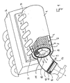
- FIG. 1 illustrates a cylindrical housing 1 made of rustproof stainless steel in the immediate vicinity of an engine block 2 of a diesel engine, to which it is connected via an exhaust gas outlet 3.
- the exhaust gases are introduced tangentially into an annular flow channel 4, in which they flow according to arrows 5 around a layered hollow cylinder 6. In this way, the particles contained in the exhaust gas come into contact over a large area with the outer surface of the hollow cylinder 6 and its layers.
- the hollow cylinder 6 consists of a perforated sheet jacket 7, a winding of wire mesh 8 and a catalytically coated material 9 provided with interconnecting pores.
- the hollow cylinder 6 encloses a cylindrical outlet space 10 with an axial outlet 11, which is connected to an outlet tube 12 connected is.
- the perforated sheet jacket 7 is preferably made of stainless steel. In this construction, the exhaust gases and the particles contained therein are guided radially from the outside through the hollow cylinder 6 and then exit axially into the outlet pipe 12.
- the particles on the perforated sheet jacket 7 and in particular on the wire mesh 8 generate frictional heat, which leads to heating of the particles, the perforated sheet jacket 7 and the wire mesh 8.
- the wire mesh With sufficient cynetic energy, the wire mesh is made to glow. This temperature increase and the catalytic addition lead to the auto-ignition temperature of the soot particles being reached.
- the soot particles When passing through the hollow cylinder 6, the soot particles are burned.
- the wire mesh 8 has the function of a heat store. At the same time, it also serves as an elastic mounting for the catalytic material 9, which is mechanically relatively sensitive when it is designed as a porous foam ceramic.
- the wire mesh 8 can be wrapped around the catalytic material 9 in a single layer or in several layers. In principle, it is also possible to use 8 steel wool instead of the wire mesh.
- the wire mesh 8 can also be coated with catalytic material.
- an insert of further wire mesh 13 is arranged in the outlet pipe 12 transversely to the direction of flow and is surrounded in a cage made of rust-free mesh sieves 14 or perforated sheet metal.
- a further insert arranged transversely to the direction of flow, made of highly porous catalytic material 16 or of a catalytically coated honeycomb body.
- the further wire mesh 13, which can be coated with catalytic material, serves like the wire mesh 8 as a heat accumulator and incandescent body, which promote the soot particle combustion.
- the flow channel 4 runs in a spiral, the housing 1 being designed as a spiral housing.
- a loose layer of wire mesh 8, which is coated with catalytic material, is inserted into the spiral.
- the combustion of the soot particles in the exhaust gas of the diesel engine is in turn promoted by the fact that due to the particle friction on the wire mesh 8, frictional heat is generated which brings the soot particles into the self-ignition temperature range.
- This area is reduced by adding the catalytic material.
- the surface of the housing 1 can also be roughened.
- a shaft 17 is arranged coaxially to the housing 1 in the outlet space 10. It carries a paddle wheel 18 which is driven by the exhaust gas emerging from the volute casing. The pitch of the impeller 18 is selected so that the exhaust gases are blown out of the outlet space 10 into the outlet pipe 12.
- a drive disk 20 is attached to a shaft end 19 in a rotationally fixed manner and can serve as an auxiliary drive.
- FIG 3 shows a view of the paddle wheel 18 in the axial direction.
- FIG. 2 further illustrates an oxygen supply into the outlet connection 3, with which the exhaust gas is enriched with oxygen before it enters the housing 1 to support the combustion process.
- the oxygen supply comprises a distributor 25 and a first and second feed line 21, 22.
- the first feed line 21 leads from a first heat exchanger 23 directly on the engine block 2 to a second heat exchanger 24, which is arranged in the form of a spiral downstream after the insert 16 in the outlet pipe 12 is. From there, the preheated oxygen is fed into the distributor 25 via the second feed line 22.
- the temperature of the supplied oxygen is thus increased on the one hand by the engine heat and on the other hand by the exhaust gas heat.
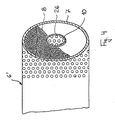
- Figure 4 shows an alternative embodiment of the hollow cylinder 6 ', as shown in Fig. 1. It consists of an outer perforated sheet jacket 7 and a perforated sheet inner jacket 26, both preferably made of stainless steel. In between is wire mesh 8, which can be wound in several layers. The wire mesh 8 is coated with catalytic material to lower the self-ignition temperature of the soot particles.
- This hollow cylinder 6 also has the function of a guide device which directs the particles circulating around the hollow cylinder 6 at high speed radially from the outside inwards into the outlet space 10, which is delimited by the perforated sheet metal inner jacket 26.
Landscapes
- Engineering & Computer Science (AREA)
- Chemical & Material Sciences (AREA)
- Combustion & Propulsion (AREA)
- Mechanical Engineering (AREA)
- General Engineering & Computer Science (AREA)
- Chemical Kinetics & Catalysis (AREA)
- Health & Medical Sciences (AREA)
- Toxicology (AREA)
- Processes For Solid Components From Exhaust (AREA)
- Exhaust Gas After Treatment (AREA)
Abstract
Description
- Die Erfindung betrifft eine Vorrichtung zur Rußpartikel-Verbrennung in der Abgasanlage eines Dieselmotors.
- Bekanntlich enthalten die Abgase von Dieselmotoren neben den gasförmigen Schadstoffen, wie Kohlenmonoxid, Kohlenwasserstoff-Verbindungen und Stickoxiden, auch organische und anorganische Partikeln. Diese Partikeln bestehen im wesentlichen aus Kohlenstoff, kondensierbaren und an Kohlenstoff angelagerten Kohlenwasserstoff-Verbindungen, Schwefel-Verbindungen sowie sonstigen Teilchen. Aus Gründen des Umweltschutzes versucht man, einen möglichst hohen Anteil dieser im Abgasstrom enthaltenen Partikeln zurückzuhalten. Hierzu werden Filtersysteme eingesetzt, in welchen sich die Partikeln bis zu einem bestimmten Beladungsgrad ansammeln sollen und welche danach durch eine sogen. Filterregeneration wieder in einen für den einwandfreien Betrieb des Motors erforderlichen Zustand gebracht werden.
- Diese Regeneration muß spätestens beim Erreichen des zulässigen Abgas-Gegendruckes durchgeführt werden. Bekannt sind hierfür mehrere Methoden, bei welchen die oxidierbare Partikelbeladung verbrannt wird. Falls die Abgase beim Austritt aus dem Motor eine ausreichend hohe Temperatur aufweisen, kann dies durch Selbstentzündung erfolgen. Eine andere Maßnahme besteht darin, eine zusätzliche externe Beheizung oder eine Fremdzündung vorzunehmen. Des weiteren kann eine Partikeln-Verbrennung durch Senkung der Selbstentzündungstemperatur durch Katalyse oder Zugabe von oxidationsfördernden Mitteln erfolgen. Diese Maßnahme wird im Hinblick darauf ausgeführt, daß die Zündtemperatur des Rußes an sich relativ hoch liegt. Die katalytische Beschichtung führt unter günstigen Bedingungen aber bereits zu einem Abbrand bei Temperaturen unterhalb dieses Bereichs, so daß auf eine externe Zündhilfe verzichtet werden kann.
- Bei verschiedenen Betriebszuständen eines Dieselmotors liegt die Temperatur der Abgase trotzdem noch immer unterhalb der Zündtemperatur.
- Der Erfindung liegt die Aufgabe zugrunde, eine Vorrichtung zur Rußpartikelverbrennung der eingangs genannten Art anzugeben, mit welcher die Temperatur der Partikeln auf einfache Weise erhöht wird.
- Diese Aufgabe wird dadurch gelöst, daß ein ringförmiger Strömungskanal mit einem tangentialen Eintritt und mit einer radialen Leiteinrichtung vorhanden ist, daß der Leiteinrichtung in Strömungsrichtung ein zylinderförmiger Austrittsraum mit einem axialen Austritt nachgeschaltet ist, und daß im Strömungskanal Drahtgestrick angeordnet ist, das Reibungswiderstand für die durchströmenden Partikeln erzeugt.
- Ein Grundgedanke der Erfindung ist darin zu sehen, daß die kinetische Energie der mit hoher Geschwindigkeit aus dem Motor austretenden Partikeln durch Reibung in Wärmeenergie umgewandelt wird, die zu einer Erhöhung der Partikeltemperatur führt. Abhängig von der Strömungsgeschwindigkeit ist es hierbei möglich, die Partikelntemperatur bis zu 80 °C zu erhöhen. Die Erfindung hat den Vorteil, daß Rußpartikeln auch dann durch Selbstentzündung verbrannt werden, wenn die Abgastemperatur beim Austritt aus dem Motor unter dem Zündpunkt liegt. Ein weiterer Vorteil ist darin zu sehen, daß sich in der Startphase Rußpartikeln im Drahtstrick ansam meln können, und daß diese nachfolgend verbrannt werden, wenn das Drahtgestrick durch die Reibungwärme genügend aufgeheizt ist. Ein anderer Vorteil besteht darin, daß ein Vorschalldämpfer entfallen kann. Ein Kraftstoffmehrverbrauch oder ein Leistungsverlust wird vermieden.
- Eine bevorzugte Ausgestaltung der Erfindung besteht darin, daß die radiale Leiteinrichtung aus einem Spiralgehäuse besteht. Alternativ dazu kann es auch zweckmäßig sein, daß die radiale Leiteinrichtung aus Leitlamellen besteht, die tangential oder radial ausgerichtet sind.
- Es kann auch zweckmäßig sein, daß die Leiteinrichtung aus einem dickwandigen, mit einer Vielzahl von Durchtrittsöffnungen versehenen Hohlzylinder aus katalytisch beschichtetem Material besteht, daß dieser Hohlzylinder mit dem Drahtgestrick umwickelt ist, und daß um das Drahtgestrick ein Ringraum zur Zirkulation der Partikeln vorhanden ist. Alternativ kann dieser Hohlzylinder auch aus einer Schaumkeramik ausgebildet sein.
- Zur mechanischen Stabilisierung des Drahtgestricks und des hochporösen Hohlzylinders kann es zweckmäßig sein, daß das Drahtgestrick mit einem Lochblechmantel umgeben ist. Auf diese Weise wird verhindert, daß die mit hoher Geschwindigkeit aus dem Motor austretenden Partikeln Drahtgestrick oder poröses Material abtragen.
- Es kann auch vorteilhaft sein, das Drahtgestrick mit katalytischem Material zu beschichten. Auf diese Weise kann der hochporöse Hohlzylinder verkleinert oder eingespart werden. Als weitere Alternative für die radiale Leiteinrichtung ist es möglich, zwischen dem zylinderförmigen Austrittsraum und einem äußeren Ringraum das Drahtgestrick in der Form eines Hohlzylinders anzuordnen und den inneren und äußeren Zylindermantel aus Lochblech herzustellen.
- Es kann auch vorteilhaft sein, daß nach dem Austritt ein weiteres Drahtgestrick quer zur Strömungsrichtung ange ordnet ist, in welchem eventuell noch unverbrannte Partikeln oxidiert werden.
- Die Verbrennung wird ferner dadurch gefördert, daß der Strömungskanal mit einer Sauerstoffzuführung versehen ist. Vorzugsweise umfaßt die Zuführung einen Wärmetauscher am Motorgehäuse und/oder an der Abgasanlage.
- Für den Fall, daß die Leiteinrichtung aus radial, tangential oder spiralförmig ausgerichteten Leitflächen besteht, ist es besonders vorteilhaft, daß im zylinderförmigen Austrittsraum ein von den Abgasen angetriebenes Schaufelrad angeordnet ist. Durch diese Maßnahme wird das Umlenken und Ausströmen des Abgases in axialer Richtung erleichtert. Zusätzlich kann an der Welle des Schaufelrades eine Hilfsenergie abgegriffen werden.
- Nachfolgend wird die Erfindung anhand von zwei in der Zeichnung dargestellten Ausführungsbeispielen weiter beschrieben.
- Figur 1, 2 u. 4 zeigen jeweils in einer teilweise angeschnittenen perspektivischen Ansicht schematisch eine Vorrichtung zur Rußpartikelverbrennung in der Abgasanlage eines Dieselmotors.
- Fig. 3 zeigt eine Einzelheit der Vorrichtung gem. Fig. 2.
- Die Figur 1 veranschaulicht ein zylinderförmiges Gehäuse 1 aus rostfreiem Edelstahl in unmittelbarer Nachbarschaft zu einem Motorblock 2 eines Dieselmotors, mit welchem es über Abgas-Austrittsstutzen 3 verbunden ist. Die Abgase werden tangential in einen ringförmigen Strömungskanal 4 eingeleitet, in welchem sie gemäß Pfeilen 5 um einen schichtweise aufgebauten Hohlzylinder 6 strömen. Auf diese Weise gelangen die im Abgas enthaltenen Partikel großflächig in Kontakt mit der Manteloberfläche des Hohlzylinders 6 und dessen Schichten.
- Der Hohlzylinder 6 besteht von außen nach innen aus einem Lochblechmantel 7, einer Wicklung aus Drahtgestrick 8 und aus einem mit interkonnektierenden Poren versehenen, katalytisch beschichteten Material 9. Der Hohlzylinder 6 umschließt einen zylinderförmigen Austrittsraum 10 mit einem axialen Austritt 11, der mit einem Ausgangsrohr 12 verbunden ist. Der Lochblechmantel 7 ist bevorzugt aus rostfreiem Stahl gefertigt. Bei dieser Konstruktion werden die Abgase und die darin enthaltenen Partikeln radial von außen durch den Hohlzylinder 6 geleitet und treten dann axial in das Ausgangsrohr 12 aus.
- Bei ihrer Zirkulation um den Hohlzylinder 6 erzeugen die Partikeln am Lochblechmantel 7 und insbesondere am Drahtgestrick 8 Reibungswärme, die zu einer Aufheizung der Partikeln, des Lochblechmantels 7 und des Drahtgestricks 8 führt. Bei genügender kynetischer Energie wird das Drahtgestrick zum Glühen gebracht. Diese Temperaturerhöhung und der katalytische Zusatz führen dazu, daß die Selbstentzündungstemperatur der Rußpartikeln erreicht wird. Beim Durchtritt durch den Hohlzylinder 6 werden also die Rußpartikel verbrannt.
- Das Drahtgestrick 8 hat die Funktion eines Wärmespeichers . Zugleich dient es auch als elastische Lagerung für das katalytische Material 9, welches mechanisch relativ empfindlich ist, wenn es als poröse Schaumkeramik ausgeführt ist.
- Das Drahtgestrick 8 kann in einer einzigen Lage oder in mehreren Lagen um das katalytische Material 9 gewickelt sein. Grundsätzlich ist auch möglich, anstelle des Drahtgestricks 8 Stahlwolle zu verwenden.
- Zur Förderung des katalytischen Effekts kann das Drahtgestrick 8 auch mit katalytischem Material beschichtet sein.
- Zur Nachreinigung der Abgase und zur Nachverbrennung von eventuell noch vorhandenen Rußpartikeln ist im Ausgangsrohr 12 quer zur Strömungsrichtung eine Einlage aus weiterem Drahtgestrick 13 angeordnet, das in einem Käfig aus rostfreien Gittersieben 14 oder Lochblech umgeben ist. Daran schließt sich nach einem Zwischenraum 15 eine weitere, quer zur Strömungsrichtung angeordnete Einlage aus hochporösem katalytischem Material 16 oder aus einem katalytisch beschichteten Wabenkörper an. Das weitere Drahtgestrick 13, welches mit katalytischem Material beschichtet sein kann, dient wie das Drahtgestrick 8 als Wärmespeicher und Glühkörper, welche die Rußpartikelverbrennung begünstigen.
- In Figur 2 sind gleiche Teile wie in Figur 1 mit gleichen Bezugszeichen versehen, so daß diese Teile im einzelnen nicht weiter erläutert werden. Bei diesem Ausführungsbeispiel verläuft der Strömungskanal 4 spiralförmig, wobei das Gehäuse 1 als Spiralgehäuse ausgebildet ist. In die Spirale ist eine lose Schicht aus Drahtgestrick 8 eingelegt, welches mit katalytischem Material beschichtet ist. Die Verbrennung der Rußpartikeln im Abgas des Dieselmotors wird wiederum dadurch gefördert, daß aufgrund der Teilchenreibung am Drahtgestrick 8 Reibungshitze entsteht, welche die Rußpartikeln in den Selbstentzündungstemperaturbereich bringt. Durch Zusatz des katalytischen Materials wird dieser Bereich abgesenkt. Um Reibungswärme zu erzeugen, kann die Oberfläche des Gehäuses 1 auch angerauht sein. Im Austrittsraum 10 ist eine Welle 17 koaxial zum Gehäuse 1 angeordnet. Sie trägt ein Schaufelrad 18, welches von dem aus dem Spiralgehäuse austretenden Abgas angetrieben wird. Die Steigung des Schaufelrades 18 ist so gewählt, daß die Abgase aus dem Austrittsraum 10 in das Ausgangsrohr 12 geblasen werden.
- Zusätzlich ist an einem Wellenende 19 eine Antriebsscheibe 20 drehfest angebracht, die als Hilfsantrieb dienen kann.
- Eine Ansicht des Schaufelrades 18 in Achsrichtung zeigt Figur 3.
- Die Figur 2 veranschaulicht ferner eine Sauerstoffzuführung in die Austrittsstutzen 3, mit welchen eine Sauerstoffanreicherung des Abgases vor dem Eintritt in das Gehäuse 1 zur Unterstützung des Verbrennungsvorgangs vorgenommen wird. Die Sauerstoffzuführung umfaßt einen Verteiler 25 sowie eine erste und zweite Zuleitung 21, 22. Die erste Zuleitung 21 führt von einem ersten Wärmetauscher 23 unmittelbar am Motorblock 2 zu einem zweiten Wärmetauscher 24, der in Form einer Spirale stromabwärts nach dem Einsatz 16 im Ausgangsrohr 12 angeordnet ist. Von dort wird der vorgewärmte Sauerstoff über die zweite Zuführleitung 22 in den Verteiler 25 geleitet. Die Temperatur des zugeführten Sauerstoffs wird somit einerseits durch die Motorwärme und andererseits durch die Abgaswärme erhöht.
- Die Figur 4 zeigt eine alternative Ausbildungsform des Hohlzylinders 6′, wie er in Fig. 1 dargestellt ist. Er besteht hierbei aus einem äußeren Lochblechmantel 7 und einem Lochblech-Innenmantel 26, beide bevorzugt aus rostfreiem Edelstahl. Dazwischen befindet sich Drahtgestrick 8, das in mehreren Lagen aufgewickelt sein kann. Das Drahtgestrick 8 ist mit katalytischem Material zur Senkung der Selbstentzündungstemperatur der Rußpartikel beschichtet. Auch dieser Hohlzylinder 6 hat die Funktion einer Leiteinrichtung, welche die um den Hohlzylinder 6 mit hoher Geschwindigkeit zirkulierenden Partikeln radial von außen nach innen in den Austrittsraum 10 lenkt, der vom Lochblech-Innenmantel 26 begrenzt ist.
Claims (11)
dadurch gekennzeichnet, daß ein ringförmiger Strömungskanal (4) mit einem tangentialen Eintritt und mit einer radialen Leiteinrichtung vorhanden ist, daß der Leiteinrichtung in Strömungsrichtung ein zylinderförmiger Austrittsraum (10) mit einem axialen Austritt (11) nachgeschaltet ist und daß im Strömungskanal (4) Drahtgestrick (8) angeordnet ist, das Reibungswiderstand für die durchströmenden Partikeln erzeugt.
dadurch gekennzeichnet, daß die radiale Leiteinrichtung aus einem Spiralgehäuse besteht.
dadurch gekennzeichnet, daß die radiale Leiteinrichtung aus Leitlamellen besteht, die tangential oder radial ausgerichtet sind.
dadurch gekennzeichnet, daß die Leiteinrichtung aus einem dickwandigen, mit einer Vielzahl von Durchtrittsöffnungen versehenen Hohlzylinder aus katalytisch beschichtetem Material (9), insbesondere aus einer Schaumkeramik besteht, daß dieser Hohlzylinder mit dem Drahtgestrick (8) umwickelt ist, und daß um das Drahtgestrick (8) ein Ringraum zur Zirkulation der Partikeln vorhanden ist.
dadurch gekennzeichnet, daß das Drahtgestrick (8) mit einem Lochblech-Mantel (7) umgeben ist.
dadurch gekennzeichnet, daß die Leiteinrichtung aus einem inneren und äußeren Lochblech-Mantel (7,26) besteht, zwischen welchen das Drahtgestrick (8) angeordnet ist.
dadurch gekennzeichnet, daß nach dem Austritt (11) ein weiteres Drahtgestrick (13) quer zur Strömungsrichtung angeordnet ist.
dadurch gekennzeichnet, daß das Drahtgestrick (8) und/oder das weitere Drahtgestrick (13) mit katalytischem Material beschichtet ist.
dadurch gekennzeichnet, daß eine Sauerstoff-Zuführung für den Strömungskanal (4) vorhanden ist.
dadurch gekennzeichnet, daß die Sauerstoff-Zuführung einen Wärmetauscher (23, 24) am Motorgehäuse und/oder an der Abgasanlage umfaßt.
dadurch gekennzeichnet, daß im zylinderförmigen Austrittsraum (10) ein von den Abgasen angetriebenes Schaufelrad (18) angeordnet ist.
Applications Claiming Priority (2)
| Application Number | Priority Date | Filing Date | Title |
|---|---|---|---|
| DE3729367 | 1987-09-02 | ||
| DE19873729367 DE3729367A1 (de) | 1987-09-02 | 1987-09-02 | Vorrichtung zur partikel-verbrennung in der abgasanlage eines dieselmotors |
Publications (2)
| Publication Number | Publication Date |
|---|---|
| EP0306049A2 true EP0306049A2 (de) | 1989-03-08 |
| EP0306049A3 EP0306049A3 (de) | 1990-04-25 |
Family
ID=6335085
Family Applications (1)
| Application Number | Title | Priority Date | Filing Date |
|---|---|---|---|
| EP88114384A Withdrawn EP0306049A3 (de) | 1987-09-02 | 1988-09-02 | Vorrichtung zur Partikel-Verbrennung in der Abgasanlage eines Dieselmotors |
Country Status (2)
| Country | Link |
|---|---|
| EP (1) | EP0306049A3 (de) |
| DE (1) | DE3729367A1 (de) |
Families Citing this family (1)
| Publication number | Priority date | Publication date | Assignee | Title |
|---|---|---|---|---|
| DE4109847C2 (de) * | 1991-03-26 | 1993-12-09 | Daimler Benz Ag | Anordnung eines Rußfilters an einem Dieselmotor |
Family Cites Families (12)
| Publication number | Priority date | Publication date | Assignee | Title |
|---|---|---|---|---|
| DE1194640B (de) * | 1960-05-11 | 1965-06-10 | Atomkraftwerk Rheinsberg Mit B | Abscheider mit rotierenden Teilen zum Abscheiden von Schwebstoffen aus gasfoermigen Medien, insbesondere zum Reinigen von Kraftfahrzeugabgasen |
| US3485593A (en) * | 1967-06-09 | 1969-12-23 | Ethyl Corp | Exhaust treating device |
| US4104360A (en) * | 1973-02-05 | 1978-08-01 | Standard Oil Company | Process for reducing oxides nitrogen in the exhaust gas from internal combustion engines |
| GB1462993A (en) * | 1973-04-11 | 1977-01-26 | Bayerische Motoren Werke Ag | Exhaust gas filter |
| US3927525A (en) * | 1973-05-25 | 1975-12-23 | Gen Motors Corp | Engine with exhaust manifold converter-reactor |
| DE2428965A1 (de) * | 1974-06-15 | 1976-01-02 | Bosch Gmbh Robert | Abgasreaktor |
| DE2750960A1 (de) * | 1977-11-15 | 1979-05-17 | Daimler Benz Ag | Russfilter im abgasstrom von luftverdichtenden brennkraftmaschinen |
| DE3027499A1 (de) * | 1980-07-19 | 1982-02-18 | Knecht Filterwerke Gmbh, 7000 Stuttgart | Abgasfilter fuer verbrennungsmotoren |
| DE3228325A1 (de) * | 1982-07-29 | 1984-02-02 | Fa. J. Eberspächer, 7300 Esslingen | Filter- und nachverbrennungseinrichtung fuer abgase |
| DE3537976C1 (en) * | 1985-10-25 | 1987-04-23 | Didier Werke Ag | Filter device for soot particle filtration |
| DE3538105A1 (de) * | 1985-10-26 | 1987-04-30 | Man Technologie Gmbh | Filter fuer den abgasstrom einer brennkraftmaschine |
| DE8620832U1 (de) * | 1986-08-02 | 1986-09-18 | Drache Keramikfilter Produktions-GmbH, 6252 Diez | Staub- oder Rußfilter |
-
1987
- 1987-09-02 DE DE19873729367 patent/DE3729367A1/de not_active Ceased
-
1988
- 1988-09-02 EP EP88114384A patent/EP0306049A3/de not_active Withdrawn
Also Published As
| Publication number | Publication date |
|---|---|
| EP0306049A3 (de) | 1990-04-25 |
| DE3729367A1 (de) | 1989-03-16 |
Similar Documents
| Publication | Publication Date | Title |
|---|---|---|
| EP1440226B1 (de) | Offener partikelfilter mit heizelement | |
| DE60016218T2 (de) | Vorrichtung und verfahren zum entfernen von russpartikeln aus abgasen von verbrennungsprozessen | |
| EP0504719B1 (de) | Abgasfilter und/oder Katalysator | |
| EP1866591B1 (de) | Abgaswärmeübertrager, insbesondere abgaskühler für abgasrückführung in kraftfahrzeugen | |
| DE102014110592B4 (de) | Nachbehandlungskomponente | |
| EP0148358A2 (de) | Katalysator zur Verbrennung und Umwandlung von Gasen und höheren Kohlenwasserstoffen, sowie Vorrichtung zur Reduktion von Stickoxiden und Abgasnachverbrenner mit einem solchen Katalysator | |
| EP1479883A1 (de) | Verfahren und Vorrichtung zur Reinigung von Abgasen | |
| DE102006049005B4 (de) | Fluidmitnahmevorrichtung sowie damit ausgestattetes Abgassystem | |
| DE102015105559A1 (de) | Integriertes mischsystem für ein abgasnachbehandlungssystem | |
| WO2005001252A1 (de) | Abgasnachbehandlungsanlage mit einem gegenstromgehäuse, sowie entsprechendes verfahren zur abgasnachbehandlung | |
| EP3348905B1 (de) | Brennkammerbaugruppe | |
| DE102014105836A1 (de) | Verbrennungsmotor und Abgasnachbehandlungssystem | |
| WO2020260331A1 (de) | Vorrichtung zur abgasnachbehandlung | |
| EP0233860A2 (de) | Abgasreinigungseinrichtung | |
| DE19855092B4 (de) | Vorrichtung und Verfahren zum Reinigen des Abgases einer Brennkraftmaschine | |
| DE102004018393A1 (de) | Abgasnachbehandlungseinrichtung | |
| DE4210358C2 (de) | Vorrichtung zur Vergrößerung von kleinen klebrigen Partikeln | |
| EP4155513B1 (de) | Abgasführungsgehäuse | |
| DE102020129001A1 (de) | Abgasanlage mit Abgasturbolader, Ejektor und Abgaskatalysator | |
| DE3729367A1 (de) | Vorrichtung zur partikel-verbrennung in der abgasanlage eines dieselmotors | |
| WO2002102493A2 (de) | Mit russabbrennung arbeitender partikelfilter für dieselmotoren | |
| DE10300408A1 (de) | Verfahren zur Behandlung eines Fluids und Wabenkörper | |
| EP1101019A1 (de) | Vorrichtung und verfahren zur nachbehandlung der motorabgase einer brennkraftmaschine | |
| DE2248442A1 (de) | Katalysator zur katalytischen reinigung von abgasen | |
| DE2341265A1 (de) | Einrichtung zur katalytischen abgasreinigung |
Legal Events
| Date | Code | Title | Description |
|---|---|---|---|
| PUAI | Public reference made under article 153(3) epc to a published international application that has entered the european phase |
Free format text: ORIGINAL CODE: 0009012 |
|
| AK | Designated contracting states |
Kind code of ref document: A2 Designated state(s): AT BE CH DE ES FR GB GR IT LI LU NL SE |
|
| PUAL | Search report despatched |
Free format text: ORIGINAL CODE: 0009013 |
|
| AK | Designated contracting states |
Kind code of ref document: A3 Designated state(s): AT BE CH DE ES FR GB GR IT LI LU NL SE |
|
| 17P | Request for examination filed |
Effective date: 19900517 |
|
| 17Q | First examination report despatched |
Effective date: 19900905 |
|
| STAA | Information on the status of an ep patent application or granted ep patent |
Free format text: STATUS: THE APPLICATION IS DEEMED TO BE WITHDRAWN |
|
| 18D | Application deemed to be withdrawn |
Effective date: 19910116 |