EP0306028B1 - Vantail de portail ou vantail de porte composé d'un ou de plusieurs parties et muni d'une serrure à barre - Google Patents
Vantail de portail ou vantail de porte composé d'un ou de plusieurs parties et muni d'une serrure à barre Download PDFInfo
- Publication number
- EP0306028B1 EP0306028B1 EP88114299A EP88114299A EP0306028B1 EP 0306028 B1 EP0306028 B1 EP 0306028B1 EP 88114299 A EP88114299 A EP 88114299A EP 88114299 A EP88114299 A EP 88114299A EP 0306028 B1 EP0306028 B1 EP 0306028B1
- Authority
- EP
- European Patent Office
- Prior art keywords
- door leaf
- locking
- leaf
- door
- lock
- Prior art date
- Legal status (The legal status is an assumption and is not a legal conclusion. Google has not performed a legal analysis and makes no representation as to the accuracy of the status listed.)
- Expired - Lifetime
Links
Images


Classifications
-
- E—FIXED CONSTRUCTIONS
- E06—DOORS, WINDOWS, SHUTTERS, OR ROLLER BLINDS IN GENERAL; LADDERS
- E06B—FIXED OR MOVABLE CLOSURES FOR OPENINGS IN BUILDINGS, VEHICLES, FENCES OR LIKE ENCLOSURES IN GENERAL, e.g. DOORS, WINDOWS, BLINDS, GATES
- E06B3/00—Window sashes, door leaves, or like elements for closing wall or like openings; Layout of fixed or moving closures, e.g. windows in wall or like openings; Features of rigidly-mounted outer frames relating to the mounting of wing frames
- E06B3/70—Door leaves
- E06B3/82—Flush doors, i.e. with completely flat surface
- E06B3/822—Flush doors, i.e. with completely flat surface with an internal foursided frame
-
- E—FIXED CONSTRUCTIONS
- E05—LOCKS; KEYS; WINDOW OR DOOR FITTINGS; SAFES
- E05B—LOCKS; ACCESSORIES THEREFOR; HANDCUFFS
- E05B63/00—Locks or fastenings with special structural characteristics
- E05B63/18—Locks or fastenings with special structural characteristics with arrangements independent of the locking mechanism for retaining the bolt or latch in the retracted position
- E05B63/20—Locks or fastenings with special structural characteristics with arrangements independent of the locking mechanism for retaining the bolt or latch in the retracted position released automatically when the wing is closed
-
- E—FIXED CONSTRUCTIONS
- E05—LOCKS; KEYS; WINDOW OR DOOR FITTINGS; SAFES
- E05C—BOLTS OR FASTENING DEVICES FOR WINGS, SPECIALLY FOR DOORS OR WINDOWS
- E05C9/00—Arrangements of simultaneously actuated bolts or other securing devices at well-separated positions on the same wing
- E05C9/04—Arrangements of simultaneously actuated bolts or other securing devices at well-separated positions on the same wing with two sliding bars moved in opposite directions when fastening or unfastening
-
- E—FIXED CONSTRUCTIONS
- E06—DOORS, WINDOWS, SHUTTERS, OR ROLLER BLINDS IN GENERAL; LADDERS
- E06B—FIXED OR MOVABLE CLOSURES FOR OPENINGS IN BUILDINGS, VEHICLES, FENCES OR LIKE ENCLOSURES IN GENERAL, e.g. DOORS, WINDOWS, BLINDS, GATES
- E06B3/00—Window sashes, door leaves, or like elements for closing wall or like openings; Layout of fixed or moving closures, e.g. windows in wall or like openings; Features of rigidly-mounted outer frames relating to the mounting of wing frames
- E06B3/70—Door leaves
- E06B2003/7046—Door leaves with provisions for locks, hinges or other fittings
Definitions
- the invention relates to a single or multi-part door or door leaf with the features of the preamble of claim 1.
- a known door leaf of the type mentioned - DE-U-7804269 - shows a lock with flush to the longitudinal center of the lock case adjoining, up and down acting locking bars, so that the latter seen relatively far in view of the inclusion of the lock from the front face of the door leaf close to the lock are arranged inside the door leaf.
- the lock case is to be received in a U-shaped frame profile which is open towards this end face of the door leaf.
- a locking device that holds the locking bars in the open position until the closed position of the door leaf is reached is not provided.
- the invention has for its object to make a door leaf of the type mentioned in terms of the arrangement of the rod lock much easier to handle both for assembly and in particular for repair, and also with regard to a possibly provided locking device or its replica and maintenance.
- the locking bar device is freely accessible from the outside, and it is also easily possible to lock the lock in the web area of this profile area of the door to be arranged so that it can be removed from its lock pocket.
- all parts of the bar lock are not only easy to assemble, they are also accessible for repairs and maintenance work without effort and without removing the door leaf or leaf.
- the end-side receiving space for the rods can be closed off by a sealing bead, as is customary in gates of this type, so that there is also no particular risk of contamination or the like.
- a locking device for holding the locking bar device in an opening position previously brought about with the aid of the lock actuation until the door leaf or gate leaf is in the closed position is easy to monitor and can also be retrofitted at least as part of the locking engagement on one of the locking bars.
- the door leaf or the door leaf wing 1 - for example, as a closing part of a multi-part door leaf - according to the exemplary embodiment is provided all around with an outwardly opening U-profile-shaped design 4 of the end face 2, which in the present case particularly applies to the door leaf 1 in the closing direction front edge area 3 is important.
- a U-shaped rail 4 is used, the web area 5 of which is arranged facing the door leaf interior 12, while the legs 6 of the U-shaped rail 4 protrude outwards and with the end regions of the adjoining them on the outside, inside and outside door leaf cover plates 7 are each folded back onto themselves so that bead-shaped edge areas 9 projecting on the end face are formed.
- a sealing bead 8 is provided with rear grip lugs 10 with which it grips the edge regions 9 from the profile interior 15 and is thus held on the profile rail 4 so as to protrude towards the front.
- a lock 11 is arranged with a lock case engaging in the door leaf interior 12 in connection to the web area 5 of the U-profile 4, engages - as can be seen particularly in FIGS. 3 and 4 - a corresponding recess 32 in the web area 5 of the U-profile 4 and is fixed with the aid of a conventional lock case shield 31 on its outwardly directed web side.
- a conventional lock case shield 31 on its outwardly directed web side.
- two locking bars 13 and 14 are embedded and guided in the longitudinal direction of the profile, as shown in FIGS. 1 and 2 with respect to the upward and downward end region the locking bars 13 and 14 show at 29.
- the exemplary embodiment accordingly shows a locking bar device which has a locking action both upwards and downwards.
- the mutually facing ends of the locking bar 13 and 14 are each held by a connecting element 17 and 18, respectively are angular.
- Each of the connecting elements 17 and 18 engages in one of the tubular ends near the lock of the associated locking bar 13 or 14 and is fixed there in a manner not shown in more detail.
- the angularly striving other end region of the connecting elements 17 and 18 engages in the interior of the lock 11 and is connected there in a manner not shown with a lock locking mechanism which, in any manner known per se, makes a progressive, approximately linear displacement movement on the locking rods 13 and 14 transmitted via the connecting elements 17 and 18 when an opening-rotating movement is transmitted to the lock nut having the square opening 19 by means of a pivoting actuation of a door handle which is applied in a counterclockwise direction parallel to the door leaf plane, and vice versa.
- This also ensures a longitudinal displacement guidance of the locking bars 13 and 14 to the extent necessary for the locking arrangement to be described later.
- the locking bars are made of solid material in their engagement area and, as viewed towards the lock 11, are subsequently formed as actuating tubes.
- the locking bars 13 and 14 are by appropriate rotation of the lock nut 19 for the opening process of the door leaf - Fig. 1 - retracted to the lock 11, so are located outside the locking engagement points 27 of the upper frame profile 26 and the lower stop profile 33. In In this retracted position, the locking bars 13 and 14 are held against the force of the tension springs 16 assigned to them in the lock area even when the not shown Door handle and thus the lock nut 19 are no longer applied in the opening direction.
- the locking bar 13 working upwards is namely gripped in its upward end region by a latching device 20 or its latch 21, in particular in a force-locking manner, and held in the open position as long as a scanner in the form of a scanning trap signals the open position of the door leaf 1, as is shown in FIG 1 is shown, ie the scanning trap 23 projects with a part of its scanning inclined surface 28 beyond the upper frame profile 26.
- the scanning trap 23 is acted upon in this “open signal position” by a compression spring 22, which is arranged between a bracket 30 held fixed to the door leaf and a shoulder of the scanning trap 23 facing it.
- the catch 21, which engages at the upper end region of the upwardly locking locking bar 13, is pivotably mounted at 24 door leaf and, in the manner of a one-armed lever in the central region thereof, is held at an angle by the compression spring 22 relative to the shoulder of the scanning latch 23 in the open position and engages in this position in a blocking manner on the locking bar 13.
- Fig. 2 shows the situation when the door leaf or the folding leaf 1 comes into the closed position.
- the downward-acting locking bar 14 is positively connected by its coupling, which is effective in both directions of movement, in the lock area with the upward-working locking bar 13, so that the locking device 20 acting on the upward-acting locking bar 13 acts in the same way on the downward-acting locking bar in the open position stops and releases in the closed position.
- This clutch can also include the door handle of the lock 11 in a simple manner, but it can also act on the locking mechanism of the lock in the manner of a one-way clutch only for the opening process.
- the spring loading of the locking bars can also be accomplished differently than with individual tension springs 16, in particular by means of a compression spring which is supported between the locking bars and with one end thereof.
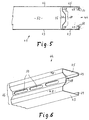
- FIGS. 5 and 6 show a profile rail with a modified profile cross section, which due to its stability can take the place of the profile rail 4 according to FIGS. 1-4.
- Both profile rails are distinguished by special strength properties which allow the wall thickness of the profile rails to be made relatively thin, for example approximately like that of the cover plates of the leaf wing.
- the reproduced edge region of a door or door leaf wing 41 shows two broken-off reproduced cover plates 42 and 43, which accommodate a frame part made of a ⁇ -shaped profile 44 between them.
- the arrangement is such that the freely projecting legs 45 of the profile 44 run in parallel to the freely projecting edge regions of the cover plates 42 and 43.
- a trapezoidal bulge 47 is provided centrally between the legs 45 and is arranged slightly protruding into the space between the legs 45.
- web areas 48 are provided which run at right angles to the legs 45.
- the freely projecting edges of the legs 45 of the profile 44 are provided with bevels 49 which are directed towards one another.
- the cover plates 42 and 43 are provided with bends which initially protrude freely at right angles for assembly and then assume a U-shaped shape when the press is closed.
- These U-shaped bends 51 also include the folds 49 at the ends of the legs 45, as shown in FIG. 5.
- the end regions of the bends 51 of the cover plates 42 and 43 thus point approximately parallel to the legs 45 and run freely into the interior between the legs 45 of the profile 44.
- a row of elongated holes 50 is provided in the bulging part of the trapezoidal bulge 47, that is to say in the smaller trapezoidal area, which extend in the longitudinal direction of the profile and are at a relatively small distance from one another .
- These elongated holes 50 serve to interrupt the heat transfer.
- the cover plates 42 and 43 between them and closed at the end by the profiles 44 form a cavity 52 between them, which is sealed in that the elongated holes 50 are glued as seen from the inside of the door leaf. The thermal bridge interruption is thus retained.
- the dimensional stability of the door leaf wing is particularly increased in that the cavity 52 formed by the frame parts and the two cover plates is completely filled with a plastic compound, namely by a foaming compound which has adhesive properties.
- a plastic compound namely by a foaming compound which has adhesive properties.
- the procedure is such that the foamable plastic mass is introduced as a pulp into a cavity 52 which is still open upwards through a lower cover plate and the profiles 44, if appropriate after sealing them.
- the upper cover plate 42 is then applied.
- the foam foams accordingly delayed, so that it is possible to either immediately close a press that holds the cover plates at a predetermined distance from each other, so that a precisely fitting wing structure is created under the foaming plastic, and then bending the cover plate edges around the free legs of the To make profiles around.
Landscapes
- Engineering & Computer Science (AREA)
- Structural Engineering (AREA)
- Civil Engineering (AREA)
- Extensible Doors And Revolving Doors (AREA)
- Gates (AREA)
Claims (17)
- Vantail de porte ou de portail (1) en une ou plusieurs parties, dont le bord (3) situé en avant dans le sens de fermeture porte une serrure à tiges de verrouillage agissant vers le haut et/ou vers le bas, en particulier vantail de fermeture d'une porte réglable, d'une porte coulissante ou analogue, dans lequel :- un système de tiges de verrouillage comportant au moins une tige guidée pouvant coulisser parallèlement au plan du vantail et perpendiculairement à la direction de déplacement du vantail, est soumis, en position de verrouillage, à l'action de ressorts,- une serrure (11) située dans la zone de manoeuvre du vantail, a sa poignée de manoeuvre à la main reliée en entraînement au système de tiges de verrouillage et est équipée d'un dispositif de fermeture,- le vantail (1), sur la face frontale (2) de son bord (3) situé en avant dans le sens de fermeture est équipé d'un profilé présentant perpendiculaire à la direction de déplacement du vantail (1) une section (4) sensiblement en U ou en sigma, dont la base (5) est située vers l'intérieur (12) du vantail et dont les ailes, sont parallèles aux parois internes et externes (7) du vantail et dépassent frontalement vers l'avant, en particulier en alignement avec une de ces parois (7),- le (ou les) barre(s) de verrouillage (13, 14) est (sont) montée(s) coulissante(s) longitudinalement dans le volume interne (15) du profilé, entre les ailes (6), cette (ou ces) barre(s)s étant reliée(s) au mécanisme de verrouillage situé à l'intérieur de la serrure, par des éléments de liaison (17, 18),caractérisé en ce que,- le profilé (4) occupe toute la face frontale du vantail (1) située à l'opposé de l'articulation de ce vantail,- la serrure (11) est montée le long de la face tournée vers l'intérieur du vantail, de la base (5) du profilé (4),- la (ou les) tiges(s) de verrouillage (13, 14) est (sont) décalée(s) par rapport au boitier de serrure,- le vantail est équipé d'un dispositif d'arrêt (20) muni d'un arrêtoir (21) qui maintient la ou les tiges (13, 14) en position d'ouverture et qui est relié à un détecteur (23), ayant en particulier la forme d'un pêne qui détecte la position de fermeture du vantail (1) en opérant le long de celui-ci, et qui, observé depuis la ou les tiges (13, 14) en direction du côté opposé à l'extrémité de fermeture du vantail, est proche de la (ou des) tige(s), l'arrêtoir (21) en position de fermeture du vantail libérant la (ou les) tige(s) de verrouillage précontrainte(s) élastiquement, le dispositif d'arrêt (20) étant situé près de l'extrémité supérieure de la (ou des) tige(s) (13, 14).
- Vantail selon la revendication 1, caractérisé en ce que les deux tiges de verrouillage (13, 14) sont reliées, dans chaque position, par le mécanisme de la serrure de manière qu'un seul dispositif d'arrêt (20), dispose notamment à la partie supérieur du vantail, maintienne les deux tiges (13, 14) en position d'ouverture et les libère en position de verrouillage.
- Vantail selon une des revendications 1 ou 2, caractérisé en ce que la serrure (11) est équipée d'un poussoir de porte que l'on peut déplacer en la faisant basculer parallèlement au plan du vantail.
- Vantail selon la revendication 1, caractérisé en ce que le poussoir de porte est en prise par l'intermédiaire d'un accouplement unidirectionnel, avec la liaison d'entraînement des deux tiges de verrouillage.
- Vantail selon une des revendications 1 à 4, caractérisé en ce que le détecteur (23) comporte une face plane oblique (28) qui dans la direction du mouvement de fermeture du vantail (1) constitué d'un battant est orientée perpendiculairement à la direction longitudinale de l'huisserie (26), en particulier de sa partie supérieure.
- Vantail selon une des revendications 1 à 4, caractérisé en ce que le détecteur comporte une surface d'arrêt oblique, qui, dans la direction du mouvement de fermeture du vantail constitué par un panneau coulissant, est dirigé selon la direction longitudinale de l'huisserie portant le point de prise de verrouillage de la tige correspondante.
- Vantail selon une des revendications 1 à 6, caractérisé en ce que le système de tiges de verrouillage (13, 14) est soumis, en position de fermeture, à la précontrainte élastique d'un dispositif à ressorts (16), situé en particulier à l'intérieur de la serrure.
- Vantail selon une des revendication 1 à 6, caractérisé en ce que le système des tiges de verrouillage est soumis, en position de fermeture, à la précontrainte élastique d'un dispositif à ressorts qui, dans le cas de deux tiges de verrouillage, est situé en particulier entre ces tiges ou entre des éléments de liaison de ces tiges.
- Vantail selon une des revendications 1 à 8, caractérisé en ce que le volume enfermé entre les ailes (6) du profilé (4) est couvert par un joint d'étanchéité (8) en forme de boudin situé en avant du vantail par rapport au sens de deplacement de celui-ci et qui est maintenu en particulier au niveau des bords des ailes (9) par des prises (10) qu'il exerce en arrière de replis des tôles de la porte, caractérisé en ce que le profil (44) des parties de cadre présente une section en forme approximative d'un sigma (Σ).
- Vantail selon une des revendications 1 à 9, caractérisé en ce que la base (46) du profilé (44) à section en forme de sigma présente en section un bombement (47) de forme trapézoïdale avançant légèrement à l'intérieur des ailes (45).
- Vantail selon la revendication 10, caractérisé en ce qu'entre le bombement (47) trapézoïdal et chacune des ailes (45) la base comporte une zone (48) perpendiculaire aux ailes (45).
- Vantail selon une des revendications 1 à 11, caractérisé en ce que les bords libres des ailes (45) du profilé (44) a section en forme de sigma présentent des rabats (49), dirigés l'un vers l'autre.
- Vantail selon une des revendications 1 à 12, caractérisé en ce que l'épaisseur de la paroi du profilé (44) à section en forme de sigma correspond à celle des tôles de recouvrement (42, 43), qui est de préférence de l'ordre de 0,5 mm.
- Vantail selon une des revendication 10 à 13, caractérisé en ce que la zone du bombement trapézoïdal (47) située en avant est percée de boutonnières (50) peu espacées, alignées selon la direction longitudinale du profilé.
- Vantail selon une des revendications 1 à 14, caractérisé en ce que les rabats (51) des tôles de recouvrement (42, 43) enveloppent les bords libres et les replis éventuels (49) des ailes (45) du profilé (44), à section en forme de sigma, en dessinant un U.
- Vantail selon une des revendications 10 à 15, caractérisé en ce que le volume creux (52), délimité par les tôles de recouvrement s (42, 43) dépourvues d'ouvertures et par les parties du cadre, fermées ou rendues étanches par obturation des boutonnières du profilé (44), est entièrement rempli par une mousse obtenue par durcissement d'une matière plastique.
- Vantail selon la revendication 16, caractérisé en ce que les tôles de recouvrement (42, 43) et les parties du cadre en profilé (44) sont collées les unes aux autres par la matière plastique cellulaire.
Applications Claiming Priority (4)
| Application Number | Priority Date | Filing Date | Title |
|---|---|---|---|
| DE3729366 | 1987-09-02 | ||
| DE19873729366 DE3729366A1 (de) | 1987-09-02 | 1987-09-02 | Ein- oder mehrteiliges tor- oder tuerblatt mit einem stangenschloss |
| DE3801567A DE3801567A1 (de) | 1987-09-02 | 1988-01-20 | Ein- oder mehrteiliges tor- oder tuerblatt mit einem stangenschloss |
| DE3801567 | 1988-01-20 |
Publications (3)
| Publication Number | Publication Date |
|---|---|
| EP0306028A2 EP0306028A2 (fr) | 1989-03-08 |
| EP0306028A3 EP0306028A3 (en) | 1990-08-22 |
| EP0306028B1 true EP0306028B1 (fr) | 1995-03-08 |
Family
ID=25859326
Family Applications (1)
| Application Number | Title | Priority Date | Filing Date |
|---|---|---|---|
| EP88114299A Expired - Lifetime EP0306028B1 (fr) | 1987-09-02 | 1988-09-01 | Vantail de portail ou vantail de porte composé d'un ou de plusieurs parties et muni d'une serrure à barre |
Country Status (2)
| Country | Link |
|---|---|
| EP (1) | EP0306028B1 (fr) |
| DE (2) | DE3801567A1 (fr) |
Families Citing this family (6)
| Publication number | Priority date | Publication date | Assignee | Title |
|---|---|---|---|---|
| US5289655A (en) * | 1990-02-08 | 1994-03-01 | Fausto Marmora | Safety release security grille |
| FI86907C (fi) * | 1990-09-26 | 1992-10-26 | Temet Oy | Regelanordning |
| FR2918696B1 (fr) * | 2007-07-12 | 2009-10-09 | Blindages De France Sarl | Porte blindee perfectionnee. |
| IT1398494B1 (it) * | 2010-03-11 | 2013-03-01 | Benussi | Profilo per serramenti in particolare del tipo tagliafuoco o similari nonche' serramento che include tale profilo |
| RU2535459C1 (ru) * | 2013-04-12 | 2014-12-10 | Закрытое акционерное общество "Континент ЭТС" | Противопожарное дверное полотно |
| RU2535286C1 (ru) * | 2013-04-12 | 2014-12-10 | Закрытое акционерное общество "Континент ЭТС" | Ворота противопожарные двухстворчатые (варианты) |
Family Cites Families (5)
| Publication number | Priority date | Publication date | Assignee | Title |
|---|---|---|---|---|
| DE2758824C2 (de) * | 1977-12-30 | 1982-08-12 | Naamloze Vennootschap Hörmann-Belgie, 3600 Winterslag-Genk | Torblatt für ein Falt- oder Rolltor |
| DE7804269U1 (de) * | 1978-02-14 | 1981-03-26 | Donges Stahlbau GmbH, 64293 Darmstadt | Stangenschloss fuer den gehfluegel eines mehrfluegeligen tores |
| DE2934062A1 (de) * | 1979-08-23 | 1981-03-26 | Peter 93086 Wörth Brunner | Tuerblatt und verfahren zu seiner herstellung |
| DE3142959C2 (de) * | 1981-08-04 | 1985-06-05 | BKS Sicherheitstechnik GmbH, 5040 Brühl | Treibstangenverschluß für Türen |
| DE8133873U1 (de) * | 1981-11-20 | 1982-04-08 | PREFAB Graeff & Hölzemann GmbH, 6800 Mannheim | Metalltuere |
-
1988
- 1988-01-20 DE DE3801567A patent/DE3801567A1/de not_active Ceased
- 1988-09-01 DE DE3853239T patent/DE3853239D1/de not_active Expired - Fee Related
- 1988-09-01 EP EP88114299A patent/EP0306028B1/fr not_active Expired - Lifetime
Also Published As
| Publication number | Publication date |
|---|---|
| EP0306028A3 (en) | 1990-08-22 |
| DE3853239D1 (de) | 1995-04-20 |
| EP0306028A2 (fr) | 1989-03-08 |
| DE3801567A1 (de) | 1989-08-03 |
Similar Documents
| Publication | Publication Date | Title |
|---|---|---|
| EP0666396A1 (fr) | Porte de sécurité | |
| EP2649259B2 (fr) | Ferrure facile d'utilisation pour ouvrant à déplacement parallèle | |
| EP2947239B1 (fr) | Système d'actionnement pour une fermeture de bâtiment et fermeture de bâtiment dotée d'un système d'actionnement | |
| EP2088275B1 (fr) | Profilé d'étanchéité de côtés, notamment pour profilés de cadre et installations de portes coulissantes en étant équipées | |
| EP1354545B1 (fr) | Joint pour une cloison de séparation de douche | |
| EP0306028B1 (fr) | Vantail de portail ou vantail de porte composé d'un ou de plusieurs parties et muni d'une serrure à barre | |
| DE102010005188A1 (de) | Torblatt für ein Feuerschutzschiebetor mit Schlupftür sowie Herstellverfahren | |
| EP2252751B1 (fr) | Ferrure de tige d entraînement pour une fenêtre ou une porte | |
| DE102007012152A1 (de) | Hebelarm sowie ein Türschließsystem oder Türantriebssystem für Türen mit verdeckter Führungsschiene | |
| EP2947221B1 (fr) | Fenêtre de toit et procédé de montage d'une fenêtre de toit | |
| EP1620619B1 (fr) | Fermeture de porte de vehicule | |
| DE19730033A1 (de) | Blend- und/oder Flügelrahmen eines Fensters/einer Tür | |
| EP2295684B1 (fr) | Butée pour une fenêtre, une porte ou analogue, ainsi que fenêtre, porte ou analogue dotée d'une telle butée | |
| DE3729366A1 (de) | Ein- oder mehrteiliges tor- oder tuerblatt mit einem stangenschloss | |
| DE202016101097U1 (de) | Verriegelungseinrichtung und dazugehörige Schiebetüranlage | |
| DE29709259U1 (de) | Flügeleinheit | |
| DE19938547B4 (de) | Schließvorrichtung und Schließblech | |
| CH655352A5 (de) | Fenster- oder tuerfluegel. | |
| EP2474691B1 (fr) | Porte sectionnelle dotée d'un agencement de verrouillage | |
| DE2461228B2 (de) | Verfahren zum Herstellen eines an eine jeweils vorgegebene Flügelhöhe angepaßten, einbaufertigen Fenster- oder Türverschlusses | |
| DE3008043A1 (de) | Zusatzverriegelung fuer fenster, tueren o.dgl. | |
| DE8800641U1 (de) | Ein- oder mehrteiliges Tor- oder Türblatt mit einem Stangenschloß | |
| EP1414689A1 (fr) | Verrouillage mobile pour parois coulissantes | |
| EP0672811A1 (fr) | Verrouillage de fausse manoeuvre pour une tringle de commande d'une fenêtre, d'une porte ou similaire | |
| WO2023118595A1 (fr) | Profilé de support en t pour vitrage destiné à être monté sur un profilé d'extrusion d'un cadre de porte et/ou d'un cadre de fenêtre |
Legal Events
| Date | Code | Title | Description |
|---|---|---|---|
| PUAI | Public reference made under article 153(3) epc to a published international application that has entered the european phase |
Free format text: ORIGINAL CODE: 0009012 |
|
| AK | Designated contracting states |
Kind code of ref document: A2 Designated state(s): AT BE CH DE ES FR GB GR IT LI LU NL SE |
|
| RBV | Designated contracting states (corrected) |
Designated state(s): BE DE FR NL |
|
| PUAL | Search report despatched |
Free format text: ORIGINAL CODE: 0009013 |
|
| AK | Designated contracting states |
Kind code of ref document: A3 Designated state(s): BE DE FR NL |
|
| 17P | Request for examination filed |
Effective date: 19901220 |
|
| 17Q | First examination report despatched |
Effective date: 19921126 |
|
| RAP1 | Party data changed (applicant data changed or rights of an application transferred) |
Owner name: HOERMANN-GENK NV |
|
| GRAA | (expected) grant |
Free format text: ORIGINAL CODE: 0009210 |
|
| AK | Designated contracting states |
Kind code of ref document: B1 Designated state(s): BE DE FR NL |
|
| ET | Fr: translation filed | ||
| REF | Corresponds to: |
Ref document number: 3853239 Country of ref document: DE Date of ref document: 19950420 |
|
| PGFP | Annual fee paid to national office [announced via postgrant information from national office to epo] |
Ref country code: BE Payment date: 19950724 Year of fee payment: 8 |
|
| PGFP | Annual fee paid to national office [announced via postgrant information from national office to epo] |
Ref country code: NL Payment date: 19950929 Year of fee payment: 8 Ref country code: FR Payment date: 19950929 Year of fee payment: 8 |
|
| PGFP | Annual fee paid to national office [announced via postgrant information from national office to epo] |
Ref country code: DE Payment date: 19951128 Year of fee payment: 8 |
|
| PLBE | No opposition filed within time limit |
Free format text: ORIGINAL CODE: 0009261 |
|
| STAA | Information on the status of an ep patent application or granted ep patent |
Free format text: STATUS: NO OPPOSITION FILED WITHIN TIME LIMIT |
|
| 26N | No opposition filed | ||
| PG25 | Lapsed in a contracting state [announced via postgrant information from national office to epo] |
Ref country code: FR Effective date: 19960930 Ref country code: BE Effective date: 19960930 |
|
| BERE | Be: lapsed |
Owner name: HORMANN-GENK N.V. Effective date: 19960930 |
|
| PG25 | Lapsed in a contracting state [announced via postgrant information from national office to epo] |
Ref country code: NL Effective date: 19970401 |
|
| NLV4 | Nl: lapsed or anulled due to non-payment of the annual fee |
Effective date: 19970401 |
|
| PG25 | Lapsed in a contracting state [announced via postgrant information from national office to epo] |
Ref country code: DE Effective date: 19970603 |
|
| REG | Reference to a national code |
Ref country code: FR Ref legal event code: ST |
|
| REG | Reference to a national code |
Ref country code: FR Ref legal event code: ST |