EP0305956A2 - Device for packaging cylindrical strands composed of a plurality of discoid pieces - Google Patents
Device for packaging cylindrical strands composed of a plurality of discoid pieces Download PDFInfo
- Publication number
- EP0305956A2 EP0305956A2 EP88114083A EP88114083A EP0305956A2 EP 0305956 A2 EP0305956 A2 EP 0305956A2 EP 88114083 A EP88114083 A EP 88114083A EP 88114083 A EP88114083 A EP 88114083A EP 0305956 A2 EP0305956 A2 EP 0305956A2
- Authority
- EP
- European Patent Office
- Prior art keywords
- strand
- wrapping
- wrapping station
- strands
- paper
- Prior art date
- Legal status (The legal status is an assumption and is not a legal conclusion. Google has not performed a legal analysis and makes no representation as to the accuracy of the status listed.)
- Withdrawn
Links
Images


Classifications
-
- B—PERFORMING OPERATIONS; TRANSPORTING
- B65—CONVEYING; PACKING; STORING; HANDLING THIN OR FILAMENTARY MATERIAL
- B65B—MACHINES, APPARATUS OR DEVICES FOR, OR METHODS OF, PACKAGING ARTICLES OR MATERIALS; UNPACKING
- B65B11/00—Wrapping, e.g. partially or wholly enclosing, articles or quantities of material, in strips, sheets or blanks, of flexible material
- B65B11/04—Wrapping, e.g. partially or wholly enclosing, articles or quantities of material, in strips, sheets or blanks, of flexible material the articles being rotated
-
- B—PERFORMING OPERATIONS; TRANSPORTING
- B65—CONVEYING; PACKING; STORING; HANDLING THIN OR FILAMENTARY MATERIAL
- B65B—MACHINES, APPARATUS OR DEVICES FOR, OR METHODS OF, PACKAGING ARTICLES OR MATERIALS; UNPACKING
- B65B35/00—Supplying, feeding, arranging or orientating articles to be packaged
- B65B35/30—Arranging and feeding articles in groups
- B65B35/54—Feeding articles along multiple paths to a single packaging position
-
- B—PERFORMING OPERATIONS; TRANSPORTING
- B65—CONVEYING; PACKING; STORING; HANDLING THIN OR FILAMENTARY MATERIAL
- B65B—MACHINES, APPARATUS OR DEVICES FOR, OR METHODS OF, PACKAGING ARTICLES OR MATERIALS; UNPACKING
- B65B51/00—Devices for, or methods of, sealing or securing package folds or closures; Devices for gathering or twisting wrappers, or necks of bags
- B65B51/04—Applying separate sealing or securing members, e.g. clips
- B65B51/06—Applying adhesive tape
Definitions
- the invention relates to a device for packaging cylindrical strands from a number of cattle, preferably in each case the same number of disc-shaped workpieces arranged next to one another, in particular a lid made of metal, in a wrapping made of paper, to which the workpieces are fed from an upstream counting device via one or two conveyor troughs and the a wrapping station to the side of the or the conveyor troughs, a device for unrolling, feeding and cutting and gluing the wrapping paper, a device for transferring the strand or strands into the wrapping station and for closing the wrapping at the end, a folding device and a device for applying a sealing tape to the has folded end faces of the envelope.
- Movable table is provided in the longitudinal direction of the strand, on which the cover strands are transferred from the conveying direction by means of a slide-guided gripping and clamping device.
- the movable table with the cover strand held thereon is moved against a hanging apron of the wrapping paper and a fixed table of the device and, with partial wrapping in the paper wrapping, is pushed onto the stationary table of the device, a section for wrapping the strand is cut off the web and with the help of pressure elements, which partly encompass the strand, are wrapped in the paper wrapping after the one end section of the wrapping paper has been provided with a glue strip via a glue strip.
- the strands encased in this way are transported further transversely to their longitudinal direction by the subsequent strand pushed into the wrapping station and thereby come under the influence of folding elements which act on the end face and fold the protruding sections of the paper wrapping in the manner of a cross-shaped base before, in the course of the further, transversely to the longitudinal direction of the strands-running feed the strands come between stationary pressure rails, which at the same time form the guide of a sealing adhesive tape on their sides facing the end faces of the strands, which adhesive tape is glued to the ends of the strands and is cut between adjacent strands with a knife.
- the known device builds relatively wide by the laterally displaceable table and the laterally protruding stationary table for receiving the strands advanced transversely to their longitudinal direction until the envelope is completed, so that their placement in the course of the conveying paths, in particular of metallic lids, due to the space requirement leads to considerable difficulties.
- the strands of the counted lids are sometimes so different in length that one of the two rails which engage on the end face and the associated folding elements cannot be used. If the second face cannot be folded automatically, the excess paper must be folded over manually.
- the invention is based on the object, the device mentioned in the introduction so that it can be arranged with a very narrow design in the course of the conveyor troughs for the workpieces to be packed without any significant change in the conveying path of the workpieces and even with larger differences in length of the cylindrical strands a uniform Packing density of the workpieces is achieved within the strands.
- the receptacles provided for accommodating the cylindrical strands in the device enable the strands to be transferred easily into the effective area of the clamping rails, which, by virtue of their arrangement which can be raised and lowered and laterally displaced in the raised position, make it possible to first convert a strand supplied to the device into a Transfer waiting position and clear the receiving channel or channels of the device for the next line.
- fluctuations in the supply of the workpieces to the device in particular a temporarily higher or faster supply of the workpieces, can be accepted without having to adapt the working speed of the device to the supply of the workpieces to be packaged.
- the device Since the strands are wrapped directly to the side of the respective receiving channels, the device is of narrow construction, so that it is used in the course of conveyor systems for such disc-shaped workpieces can be incorporated.
- a uniform packing density of the workpieces within the strand is achieved by means of the pressure limiting buttons which can be moved towards the strand in the wrapping station.
- the pressure limiting buttons which can be moved towards the strand in the wrapping station.
- different longitudinal dimensions of the strands result with the same packing density.
- the provided device which can be moved in the direction parallel to the longitudinal direction of the strand, for trimming the edge of the wrapping paper, its dimensions are adapted to the respective strand length in such a way that constant closure rosettes are produced on both sides of the strand.
- These closure rosettes can be formed with the help of the folding fingers during the rotation of the strand with its covering in the wrapping station and can also be fixed in the wrapping station.
- the entire arrangement is practically a single-station machine, in which the strand transferred to the drivable support rollers for wrapping is maintained while maintaining an adjustable axial pressure which is the same for all strands until the wrapping, including the closure rosettes, and their fixing is completed.
- a particularly favorable and space-saving design is achieved by training with the features of claim 2.
- the deep arrangement in the device makes it easier to insert the relatively heavy new supply rolls.
- the gluing device and the unrolling device are easily accessible from the outside, as is the device provided below the wrapping station for applying and cutting off the sealing tape.
- the device for trimming the edge of the wrapping paper is equipped with a cutting knife perforating the wrapping paper at a distance and parallel to the edge.
- the wrapping paper is perforated at a distance from one end of the strand around the strand, so that when the sheath is subsequently removed for further processing of the workpieces, the tearing of the sheath along the perforation is made considerably easier.
- Claims 10 to 12 describe the design of a device with a lowerable pressure bar provided above the wrapping station and its design. With this solution, the packaging is completely finished including the application of the fastener tapes in the wrapping station.
- the device is designed so that the closure tape ends are pressed above the wrapping station, so that a new strand can be transferred to the wrapping station while the closure tape ends are being pressed, thereby increasing the cycle times of the device.
- the drawing shows exemplary embodiments of the invention.
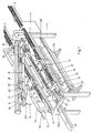
- the device shown in FIG. 1 is intended for connection to two conveyor troughs 1 and 2 arranged parallel to one another, each with a counting device 3 and 4 for the disks to be transferred along the conveyor troughs 1 and 2 into the device shaped workpieces are equipped.
- the disk-shaped workpieces are lids which are divided into strands of the same number and are to be wrapped in a wrapping of paper with an end closure of this wrapping in the device according to FIG. 1.
- the device according to FIG. 1 has a frame-shaped or table-shaped frame 5, on which receptacles 6 and 7, which run in the longitudinal direction of the frame 5, are provided in the respective extension of the conveyor troughs 1 and 2 for feeding the cover to be wrapped.
- a height-pivotable pressure beam 8 is articulated on a transverse side of the frame 5, which extends longitudinally centrally between the receiving grooves 6 and 7 and which in the direction of the double arrow 9 from the position shown in FIG lowered position parallel to the receptacles can be transferred.
- the wrapping station designated overall by 10
- the wrapping station in which the cover strands respectively removed from the receptacles 6 and 7 are wrapped in the covering. 1, a cover strand 11 can be seen in the wrapping station.
- the wrapping station 10 has two support rollers 12 and 13 which can be driven about its longitudinal axis and which, apart from the rotary movement, are held stationary in the frame 5.
- To transfer the cover strands from the receptacles 6 and 7 to the drivable Support rolls 12 and 13 of the wrapping station 10 are assigned to the receptacles on both sides of the respective strand, mutually movable clamping rails 14 and 15.
- the clamping rails 14 and 15 are each connected to actuating devices 16 and 17, with the aid of which they are moved into the clamping and release position and into a position above the receiving grooves 6 and 7 and from this raised position in the direction of the wrapping station 10 and there up to the drivable support rollers 11 and 12 can be lowered.
- the individual strands 11 can thus be removed from the receptacles, temporarily into a raised parking or Waiting position and be transferred from this to the drivable support rollers 12 and 13 of the wrapping station 10.
- the actuating devices 16 and 17 are equipped in a manner known per se with pneumatically actuatable drive elements which bring about the lifting and lateral displacement movement of the clamping rails 14 and 15.
- the sides of the clamping rails 14, 15 facing the respective cover strand 11 are expediently equipped with a non-slip and elastic coating in order to securely grasp all the covers of a strand and to be able to transfer them to the wrapping station 10 while maintaining the mutual position of the covers.
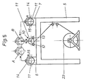
- the cover strand 11 gripped by the clamping rails 14 and 15 in the left part of FIG. 5 is first transferred to the raised position A. This position is at the same time an intermediate and waiting position, during which the associated receiving channel 6 is already free for receiving a next strand of cover.
- the cover strand 11 can then be transferred from position A to position B above the wrapping station before the lowering onto the drivable support rollers 12 and 13 takes place.
- the sequence of movements is indicated by arrows in FIG. 5.
- the return movement of the clamping rails 14 and 15 is reversed.
- the movement of the clamping rails 14 and 15 shown in the right-hand part of FIG. 5 is carried out analogously, so that the cover strands 11 can be removed from the receptacles 6 and 7 and transferred to the wrapping station 10 in the current change or in any sequence.
- the pressure bar 8 is equipped on its underside with paper guide plates 18 running in its longitudinal direction, between which at least one pressure roller 19 also running in the longitudinal direction of the pressure bar 8 is provided. In the lowered position of the pressure bar 8, the pressure roller 19 extends parallel to the drivable support rollers 12 and 13.
- a slide 20 which can be moved along this bar and which is equipped with folding fingers 21 which can be moved into a closed and a spreading position.
- a lockable abutment 22 is provided on an end face of the frame 5 see which is also equipped with folding fingers 21 like the slide 20.
- the folding fingers 21 are used in a manner yet to be described to form closure rosettes which arise towards the end of the wrapping process by transferring the folding fingers 21 into the closed position while simultaneously rotating the strand 11 already in the wrapping.
- a supply roll 23 of the web-shaped wrapping paper 24 is held in an unwinding device, generally designated 25.
- the web-shaped paper 24 is drawn off from the supply roll 23 by means of take-off rolls which are not shown in FIG. 1 and is guided between the drivable pressure rolls 12 and 13 with the aid of a feed device to be described later and under the action of the paper guide plates 18 and the pressure roll 19 around the respective one Strand 11 wrapped around in the wrapping station.
- a longitudinal cutting device 26 is provided, which is shown only schematically in FIG. 1 as a cutting wheel which can be moved transversely to the paper web 24.
- a gluing device 27 is provided to form the closure of the paper web wound around the respective strand 11, which in the example shown is designed as a nozzle bar 27 that can be moved back and forth across the paper web 24.
- the frame 5 In the area of the movable carriage 20 provided on the pressure beam 8, the frame 5 is in the directly below the drivable support rollers 12 and 13, a further slide 28 is held on a corresponding guide 28a running along the frame 5, which can be coupled to the slide 20 guided thereon in the lowered position of the pressure bar 8.
- the carriage 20 is equipped with a coupling pin 29 which engages in a corresponding bore 30 in the carriage 28.
- the carriage 28 is equipped with a device (not shown in FIG. 1 for the sake of clarity) for trimming the edge of the wrapping paper 24 and with an overall device 31 for applying the sealing tape and an associated cutting device.
- a device not shown in FIG. 1 for the sake of clarity
- an overall device 31 for applying the sealing tape and an associated cutting device.
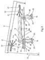
- FIG. 2 The devices for applying the sealing adhesive tape with the associated cutting devices can be seen from FIG. 2 in a schematic representation.
- the parts corresponding to FIG. 1 are also provided with the same reference numerals.
- Fig. 2 is indicated by the piston-cylinder arrangement 32 only in principle that the pressure bar 8 is transferred along the double arrow 9 in the raised or lowered position and can be brought into effect with a predetermined pressure on the lid stack 11 to be wrapped.
- FIG. 2 shows that a downward-pointing guide rod 33 is held on the slide 28 below the wrapping station 10 and holds a liftable and lowerable carrier 34 for an adhesive sealing tape roll 35.
- An adhesive tape holding plate 36 extends from the carrier 34 and runs parallel to the guide rod 33, which can be transferred with the carrier 34 when it is displaced along the guide rod 33 into a position directly in front of the end face 11a of the cover strand 11 which has already been wrapped and provided with a rosette, and back into the position shown in Fig. 2 is retractable.
- a device consisting of the same parts 33 to 36 is provided for applying the sealing adhesive tape, the downwardly projecting guide rod 33 with a guide piece for the slide 28, which is held stationary during operation of the device on the guide 28a 37 is connected.
- the cutting devices provided for cutting off the sealing adhesive tape are only indicated as knives 38 which can be moved transversely to the adhesive tape 39.
- FIG. 2 also shows that the carriage 28 is equipped with a device for trimming the edge of the paper web 24 on the carriage side.
- a co-rotating cutting knife 40 is provided in the carriage 28 on a drivable shaft 59 running along the carriage.
- a perforation knife 41 which rotates with this shaft is arranged on the shaft 59 and cuts an all-round perforation 42 into the paper web wound on the strand 11 at a distance and parallel to the trimmed edge of the paper web 24.
- Fig. 2 shows that both in the carriage 20 held longitudinally on the pressure beam 8 and in the abutment 22 each have a pressure limiting button 43, the pressure limiting button 43 in the carriage 20 pushing the carriage 20 against each other the drivable support rollers 12 and 13 located lid stack 11 determined.
- the pressure limiting button 43 of the fixed abutment 22 is subjected to a higher pressure than the pressure limiting button 43 of the slide 20, so that it acts practically like a stationary abutment.
- the pressure limit button 43 in the slide 20 exerts the same pressure on the lid stack 11 regardless of its length, so that the lid stacks to be wrapped each have the same packing density and, with larger thickness tolerances, the lid 11 is correspondingly longer or shorter.
- the cutting device in the carriage 28 ensures that, irrespective of the length of the respective stacks, the edge of the paper web 24 lying in the region of the carriage 28 is trimmed to such an extent that rosette formation is still possible.
- the perforation line 42 is also incised at the same distance from the end of the stack of covers.
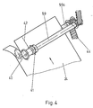
- the cutting device for trimming the edge of the paper web 24 is shown in an enlarged view in FIG. 4, but without the carriage 28 surrounding it or receiving it. Again, the same parts are provided with the same reference numerals.
- the paper web 24 is passed between two driven shafts 59 and 59a, a toothed belt drive 44 being used to drive the shafts 59 and 59a.
- the associated drive motor can be provided on or in the slide 28, for example in the form of a hydraulic motor.
- the feeding of the paper web 24 from the supply roll 23 to the lid stack 11 is shown schematically in enlarged form in FIG. 3.
- the web 24 is guided over a deflection roller 45 and between driven cooperating pull rollers 46 and 47 and further rollers 46a and 47a. Baffles not shown in the drawing are provided between the aforementioned pairs of rollers.
- the cutting device provided for cutting off the web sections has a cutting bar 48 which interacts with the cutting wheel 26.
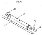
- the respective cover strands 11 transferred into the wrapping station 10 are after their transfer into the wrapping station 10 is acted upon by blow nozzles on its end faces until the pressure limiting buttons 43 come into contact, as is shown in FIG. 6 for a strand 11 located on the drivable support rollers 12 and 13 through the nozzles 65.
- the nozzles 65 can be held longitudinally displaceably on the pressure bar in order to adjust them to the respective length of the strand 11.
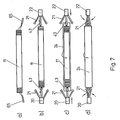
- FIG. 7 represents the individual phases of wrapping in a purely schematic manner.
- the cover strand 11 is acted on by the nozzles 65 on the end faces, as shown in FIG. 6, in such a way that the ends of the cover cannot fall over.
- the slide 20 with its folded fingers 21 advanced with its advanced pressure limiting button 43 against the strand 11 and pressed it against the pressure limiting button 43 of the abutment 22, so that it transferred into the correct position with respect to the paper web 24 and while maintaining an axial pressure is wrapped by feeding the paper web 24, as shown in phase c.
- the folding fingers 21 are now transferred into the closed position in accordance with phase d, the folding fingers interacting with the end projection of the covering in such a way that a rosette is folded.
- the pressure limiting buttons 43 are moved back into their starting position.
- sealing tape 39 is shown in the form of a partial illustration from FIG. 2 in an enlarged view and for two different positions of the adhesive tape holding plates 36 in FIGS. 8 and 9.
- FIG. 8 and 9 show the device for applying the sealing adhesive tape 39 in the area of the abutment 22 in FIG. 2.
- the adhesive tape holding plate 36 is shown in its lower starting position.
- the adhesive tape holding plate 36 has nozzle openings 36a, which are connected to a collecting channel 36b, which in turn is connected to a line 36c, via which a compressed air or suction air source can be connected.
- the nozzle openings 36a are suctioned, so that the section of the sealing tape 39 located in front of the holding plate 36 is pressed against the holding plate 36.
- the sealing tape 39 is coated on its side facing away from the holding plate 36 with adhesive.
- the section of the sealing tape 39 extending above the holding plate 36 adheres with its adhesive layer to the front rosette of the wrapping of the cover stack 11.
- the cover strand 11 provided with the covering is at rest, ie it is no longer set in rotation by the drivable support rollers 12 and 13.
- the sealing adhesive tape 39 has been applied to the front ends of the wrapped lid stacks 11, the respectively finished lid stack is pushed out of the wrapping station 10 in the longitudinal direction from the device according to FIG. 1 and thereby reaches a discharge channel 66 according to FIG. 1.
- the adhesive tape holding plate 36 is transferred from the position shown in FIG. 8 while maintaining the suction at the nozzle openings 36a into the position shown in FIG. 9 and In this position, compressed air is then applied instead of the suction of the nozzle openings 36a, as is indicated by the arrows in FIG. 9. In this way, the section of the sealing tape 39 located in front of the holding plate 36 is pressed against the rosette and fixes it. The upper end of the adhesive tape section 39 is already folded over in the direction of the cover strand. 8, a further section of the adhesive tape 39 is pulled off the roll 35 and the section in front of the holding plate 36 is again acted upon by suction air via the nozzle openings 36a, as is the case in connection with 8 has already been described.
- the pressure bar 8 or the movable carriage 20 can pivot from top to bottom 10 can be provided with rollers 68 which can be moved diametrically over the strand ends and which are held on a carriage 69 which in turn can be moved back and forth along the support 67.
- phase a namely the starting position of the resilient pressure rollers 68
- phase b is shown in the lower part, in which the pressure rollers 68 roll the protruding ends of the sealing adhesive tape 39 onto the peripheral surface of the wrapping of the strand 11 to have.
- FIG. 11 A schematic representation of how the circumferentially loose covering of the cover strands 11 is achieved, which is desirable in order to be able to remove the cover easily from the cover after opening, is illustrated in FIG. 11.
- phase a in the left part of FIG. 11 the start of the winding of the strand 11 is shown, in the right part phase b immediately before the end of the wrapping process.
- the cover strand 11 lies in the wrapping station 10 on the drivable support rollers 12 and 13, on which it is pressed by the pressure roller 19 of the lowered pressure bar 8.
- the paper web 24 for wrapping the stack 11 is guided along the guide plates 70 and 71 shown in FIG. 11 and through the drivable roller pair 46a and 47a into the gap between the drivable support roller 12 and the stack 11.
- the supplied paper web 24 slides in the area outside the support or pressure rollers 12, 13 and 19 along the inner wall surfaces of the paper guide plates 18, so that a loose wrapping is produced, as shown in phase b in the right part of FIG. 11 .
- a feed device for the strand 11 consisting of the counted lids is controllable by the counting devices 3 and 4 in connection with a facility device for inserting spacers is provided, which is shown schematically in Fig. 12 and partly in Fig. 1.
- the counting device 3 shown there is provided with a feed device 51 which can be controlled by it and which, when the desired number is reached, advances the lid of a stack 11 in the manner indicated, so that a gap 52 is created between the stack 11 and the subsequent lid.
- a feed device 51 which can be controlled by it and which, when the desired number is reached, advances the lid of a stack 11 in the manner indicated, so that a gap 52 is created between the stack 11 and the subsequent lid.
- one or more cylindrical spacers are introduced, which are smaller in diameter than the lid, so that they are not detected when the lid stack 11 is transferred from the receiving channel 6 or 7 into the wrapping station 10.
- the spacers 53 thus remaining in the receiving channel 6 or 7 are returned from the end of the receiving channel 6 or 7 back into the area of the gap 52.
- a pipeline 54 running above and at a distance parallel to the respective receiving channel 6 or 7 is provided, which is connected to connecting shafts 55 and 56.
- the spacers 53 arriving at the end of the receiving channel 6 or 7 are transferred into the pipeline 54 via a piston-cylinder arrangement 57 and conveyed there by a further piston-cylinder arrangement 58 in the direction of the beginning of the receiving channel 6 or 7, as indicated by arrows is.
- Controllable retainers in the form of piston-cylinder arrangements are provided in the connecting shaft 56, which are actuated by the feed device 51, so that one or more spacers 53 are released for falling into the gap 52 after the gap 52 has been formed.
- the device shown schematically in FIG. 2 is also partially recognizable in FIG. 1 above the receiving channel 6.
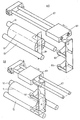
- 14 and 15 show a variant of the arrangement according to FIG. 1, the difference essentially consisting in the fact that in the arrangement according to FIGS. 14 and 15 there is no pressure bar with the elements held thereon. 14 and 15, the parts corresponding to the other figures are also provided with the same reference numerals.
- lifting and lowering support arms 60 are provided in the embodiment according to FIGS. 14 and 15, on which the pressure roller 19 and the paper guide plates 18 are held.
- the support arms 60 are held in the manner of cantilever arms on lifting or guide rods 62 which, in the example shown, are fastened via intermediate pieces 63 to the pipeline 54 running parallel to the receiving channel 6 for the return of the spacers 53.
- the support arms 60 extend in the manner of cantilevers up to the wrapping station 10 and can be moved so far in the direction of the double arrows along the vertical bars or together with them that the pressure roller 19 on the cover strand 11 located in the wrapping station 10 in the lowered position rests and in the raised position the supply of a further strand of cover from one of the receptacles 6 and 7 by means of the mutually movable clamping rails 14 and 15 is not hindered in the manner described above.
- the paper guide plates 18 held on the support beams are simultaneously formed as gripping shells in the device according to FIGS. 14 and 15 and are connected to an actuating device not shown in the figures, so that they come from a position in which they surround the strand to be wrapped at a distance. can be transferred into a clamping position in order to capture the strand which is respectively wrapped in the wrapping station 10 and provided with the fastening tapes applied on the end face and to be transferred to the raised position during the upward movement of the support arms 60. Since in this raised position the sealing tape ends are to be rolled on, in alignment with the strand in its raised position, the longitudinally displaceable resilient rollers 68, which are pivotably held on the pressure bar 8 in FIG. 1, are held in a stationary slide guide 64 and can be held by means of one in the drawing not shown drive in the direction of the double arrows with their resilient rollers 68 in the manner previously described for rolling the sealing tape ends over the strand ends and back.
- the closure tape adhesive tape ends are no longer rolled in the wrapping station 10, but in a position of the wrapped cover strand above this wrapping station.
- the wrapping station can be loaded with a new cover strand while the sealing tape ends are being rolled on.
- swivels are pivotable under the cover strand which is in the raised position Tabs 61 are provided, via which after the release of the cover strand by spreading the paper guide plates 18, the strand can roll laterally and above the wrapping station 66, which deviates from FIG. 1 and from which it is conveyed further by means of an ejection device, not shown.
- the movable slide 20 provided on the pressure bar in FIG. 1 is structurally combined with the slide 28 in the embodiment according to FIGS. 14 and 15 and forms the component 20a shown in FIG. 14, which like the slide 20 with the folding fingers 21 and a pressure limiting button is equipped, as has already been described in connection with the slide 20.
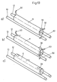
- FIG. 15 shows a schematic representation of the upper position of the support arms 60 as well as the arrangement of the inclined tabs 61 and the discharge channel provided laterally above the wrapping station 10.
- the inclined tabs 61 are articulated on the discharge trough 66. It can be seen from FIG. 15 that when the support arms 60 are in the raised position, the wrapping station 10 can be easily loaded with a new strand from one of the receptacles 6 and 7, respectively.
- the individual movement sequences and their sequence are controlled by electronics not shown in the drawing, piston-cylinder arrangements being predominantly provided for driving the individual elements of the device to be moved, but the device is not restricted to the use of these drive elements.
Abstract
Die Vorrichtung zum Verpacken zylindrischer Stränge (11) aus in gleicher Anzahl nebeneinander angeordneter scheibenförmiger Werkstücke, insbesondere Deckel, in eine Umhüllung aus Papier (24) weist wenigstens eine Aufnahmerinne (6 bzw. 7) für die Stränge und dieser zugeordnete, gegeneinander bewegbare sowie heb- und senkbare und in der angehobenen Stellung seitlich verschiebbare Klemmschienen (14,15) zur Überführung des Stranges (11) in eine seitlich neben der Aufnahmerinne (6 bzw. 7) vorgesehene Einwickelstation (10) mit antreibbaren Stützrollen (12,13) für den Strang auf. Wenigstens eine zu den Stützrollen (12,13) parallel verlaufenden Andruckrolle (19) ist in der Einwickelstation (10) auf den Strang (11) absenkbar und ein längsverschiebbarer Schlitten (20) mit einem Druckbegrenzungstaster zum Andruck des Stranges gegen ein feststehendes Widerlager (22) vorgesehen. Der Schlitten (20) und das Widerlager (22) sind mit Faltfingern zur Bildung von Verschlußrosetten und je einer Einrichtung (31) zum Aufbringen des Verschlußklebebandes auf die Rosetten ausgerüstet. Am Schlitten (20) ist eine mitbewegte Einrichtung zur Randbeschneidung des Einwickelpapieres angeordnet.The device for packing cylindrical strands (11) from the same number of disc-shaped workpieces, in particular lids, arranged side by side in a wrapping made of paper (24) has at least one receiving channel (6 or 7) for the strands and associated, mutually movable and lifting - And lowerable and laterally displaceable in the raised position clamping rails (14, 15) for transferring the strand (11) to a side next to the receiving channel (6 or 7) provided wrapping station (10) with drivable support rollers (12, 13) for the Strand on. At least one pressure roller (19) running parallel to the support rollers (12, 13) can be lowered onto the strand (11) in the wrapping station (10) and a longitudinally displaceable carriage (20) with a pressure limiting button for pressing the strand against a fixed abutment (22 ) intended. The carriage (20) and the abutment (22) are equipped with folding fingers to form closure rosettes and a device (31) for applying the sealing tape to the rosettes. A moving device for trimming the edge of the wrapping paper is arranged on the slide (20).
Description
Die Erfindung betrifft eine Vorrichtung zum Verpacken zylindrischer Stränge aus einer Viehzahl, vorzugsweise jeweils in gleicher Anzahl nebeneinander angeordneter scheibenförmiger Werkstücke, insbesondere Deckel aus Metall, in eine Umhüllung aus Papier, der die Werkstücke aus einer vorgeordneten Zähleinrichtung über eine oder zwei Förderrinnen zugeleitet werden und die eine Einwickelstation seitlich neben der oder den Förderrinnen, eine Einrichtung zum Abrollen, Zuführen sowie Schneiden und Beleimen des Einwickelpapieres, eine Einrichtung zur Überführung des oder der Stränge in die Einwickelstation sowie zum stirnseitigen Verschließen der Umhüllung eine Falteinrichtung und eine Einrichtung zum Aufbringen eines Verschlußklebebandes auf die gefalteten Stirnseiten der Umhüllung aufweist.The invention relates to a device for packaging cylindrical strands from a number of cattle, preferably in each case the same number of disc-shaped workpieces arranged next to one another, in particular a lid made of metal, in a wrapping made of paper, to which the workpieces are fed from an upstream counting device via one or two conveyor troughs and the a wrapping station to the side of the or the conveyor troughs, a device for unrolling, feeding and cutting and gluing the wrapping paper, a device for transferring the strand or strands into the wrapping station and for closing the wrapping at the end, a folding device and a device for applying a sealing tape to the has folded end faces of the envelope.
Bei bekannten Vorrichtungen der beschriebenen Art (EU-Pat.-Anm. 206 374) ist für die Aufnahme und Überführung der einzelnen Stränge ein seitlich quer zur Längsrichtung des Stranges verfahrbarer Tisch vorgesehen, auf welchen die Deckelstränge von der Förderrichtung mittels einer schlittengeführten Greif- und Klemmeinrichtung überführt werden. Der verfahrbare Tisch mit dem darauf gehaltenen Deckelstrang wird gegen eine herabhängende Schürze des Einwickelpapieres und einen feststehenden Tisch der Vorrichtung verfahren sowie unter teilweiser Einwicklung in die Papierumhüllung auf den ortsfesten Tisch der Vorrichtung geschoben, ein Abschnitt zur Umhüllung des Stranges von der Bahn abgeschnitten und mit Hilfe von Andruckelementen, welch sich z.T. umgreifend um den Strang legen, in die Papierumhüllung eingewickelt, nachdem über eine Leimleiste der eine Endabschnitt des Einwickelpapieres mit einem Leimstreifen versehen wurde. Die so umhüllten Stränge werden durch den jeweils nachfolgenden und in die Einwickelstation geschobenen Strang quer zu ihrer Längsrichtung weitertransportiert und gelangen dabei unter den Einfluß stirnseitig angreifender Faltelemente, welche die überstehenden Abschnitte der Papierumhüllung nach Art eines Kreuzbodens falten, ehe im Zuge des weiteren quer zur Längsrichtung der Stränge verlaufenden Vorschubes die Stränge zwischen ortsfeste Andruckschienen gelangen, welche auf ihren den Stirnseiten der Stränge zugekehrten Seiten gleichzeitig die Führung eines Verschlußklebebandes bilden, welches stirnseitig auf die Stränge aufgeklebt und zwischen benachbarten Strängen mit einem Messer durchtrennt wird.In known devices of the type described (EU Pat. Note 206 374) is a laterally transverse to the reception and transfer of the individual strands Movable table is provided in the longitudinal direction of the strand, on which the cover strands are transferred from the conveying direction by means of a slide-guided gripping and clamping device. The movable table with the cover strand held thereon is moved against a hanging apron of the wrapping paper and a fixed table of the device and, with partial wrapping in the paper wrapping, is pushed onto the stationary table of the device, a section for wrapping the strand is cut off the web and with the help of pressure elements, which partly encompass the strand, are wrapped in the paper wrapping after the one end section of the wrapping paper has been provided with a glue strip via a glue strip. The strands encased in this way are transported further transversely to their longitudinal direction by the subsequent strand pushed into the wrapping station and thereby come under the influence of folding elements which act on the end face and fold the protruding sections of the paper wrapping in the manner of a cross-shaped base before, in the course of the further, transversely to the longitudinal direction of the strands-running feed the strands come between stationary pressure rails, which at the same time form the guide of a sealing adhesive tape on their sides facing the end faces of the strands, which adhesive tape is glued to the ends of the strands and is cut between adjacent strands with a knife.
Die bekannte Vorrichtung baut durch den seitlich verschiebbaren Tisch sowie den seitlich ausladenden ortsfesten Tisch für die Aufnahme der quer zu ihrer Längsrichtung vorgeschobenen Stränge bis zur Vervollständigung der Umhüllung relativ breit, so daß ihre Aufstellung im Zuge der Förderwege, insbesondere von metallischen Deckeln, durch den Platzbedarf zu erheblichen Schwierigkeiten führt.The known device builds relatively wide by the laterally displaceable table and the laterally protruding stationary table for receiving the strands advanced transversely to their longitudinal direction until the envelope is completed, so that their placement in the course of the conveying paths, in particular of metallic lids, due to the space requirement leads to considerable difficulties.
Weiterhin sind für die Überführung der Stränge in die Einwickelstation und die seitliche Verschiebung des beweglichen Tisches erhebliche Aufwendungen notwendig.Furthermore, considerable expenditure is necessary for the transfer of the strands into the wrapping station and the lateral displacement of the movable table.
Bei Deckeln mit einem Bördelrand ergeben sich durch Verschleiß der Bördelwerkstoffe und/oder geringe Unterschiede in der Verformbarkeit des Metalles Abweichungen in der Stärke bzw. in der Breite des Deckelrandes, so daß bei der üblichen Anzahl der Deckel je Strang Längenunterschiede der Stränge bis zu einigen cm auftreten können. Bei der bekannten Vorrichtung müssen die für den Faltvorgang der überstehenden Enden der Umhüllung und für die Aufbringung des Verschlußklebebandes vorgesehenen Schienen bzw. Faltelemente so angeordnet werden, daß bei der maximalen Länge der Stränge diese noch zwischen den stirnseitig angreifenden Schienen und Faltelementen hindurchgeschoben werden können. Hierdurch ergeben sich Stränge mit unterschiedlich zusammengepreßten Deckeln und hierdurch bedingt unterschiedlich stramm um die Deckel greifende Umhüllungen. Diese Unterschiede machen sich bei der später für die Weiterverarbeitung der Deckel notwendigen Entnahme aus den Umhüllungen wiederum nachteilig bemerkbar.In the case of lids with a flange edge, wear of the flange materials and / or slight differences in the deformability of the metal result in deviations in the thickness or width of the lid edge, so that with the usual number of lids per strand, length differences of the strands up to a few cm may occur. In the known device, the rails or folding elements provided for the folding process of the protruding ends of the casing and for the application of the sealing adhesive tape must be arranged such that, at the maximum length of the strands, these can still be pushed between the rails and folding elements acting on the end face. This results in strands with differently compressed lids and, as a result, differently tight wrappings around the lids. These differences again have a negative impact on the removal from the wrappings that is later necessary for the further processing of the lids.
Insbesondere bei Aluminium-Deckeln sind die Stränge der abgezählten Deckel teilweise so unterschiedlich lang, daß eine der beiden stirnseitig angreifenden Schienen und die zugehörigen Faltelemente nicht verwendet werden können. Wenn die zweite Stirnseite somit nicht automatisch gefaltet werden können, ist ein manuelles Umlegen des überstehenden Papieres erforderlich.In the case of aluminum lids in particular, the strands of the counted lids are sometimes so different in length that one of the two rails which engage on the end face and the associated folding elements cannot be used. If the second face cannot be folded automatically, the excess paper must be folded over manually.
Der Erfindung liegt die Aufgabe zu Grunde, die einleitend genannte Vorrichtung so auszubilden, daß sie bei sehr schmaler Bauweise im Zuge der Förderrinnen für die zu verpackenden Werkstücke ohne nennenswerte Änderung des Förderweges der Werkstücke angeordnet werden kann und auch bei größeren Längenunterschieden der zylindrischen Stränge eine gleichmäßige Packungsdichte der Werkstücke innerhalb der Stränge erreicht wird.The invention is based on the object, the device mentioned in the introduction so that it can be arranged with a very narrow design in the course of the conveyor troughs for the workpieces to be packed without any significant change in the conveying path of the workpieces and even with larger differences in length of the cylindrical strands a uniform Packing density of the workpieces is achieved within the strands.
Gelöst wird vorstehende Aufgabe durch die im Kennzeichen des Anspruches 1 genannten Merkmale.The above object is achieved by the features mentioned in the characterizing part of claim 1.
Die zur Aufnahme der zylindrischen Stränge in der Vorrichtung vorgesehenen Aufnahmerinnen ermöglichen eine einfache Überführung der Stränge in den Wirkbereich der Klemmschienen, welche durch ihre heb- und senkbare sowie in der angehobenen Stellung seitlich verschiebbare Anordnung die Möglichkeit schaffen, einen der Vorrichtung zugeführten Strang zunächst in eine Warteposition zu überführen und die Aufnahmerinne bzw. -rinnen der Vorrichtung frei zu machen für den nächstfolgenden Strang. Hierdurch können Schwankungen in der Zuführung der Werkstücke zu der Vorrichtung, insbesondere eine vorübergehend höhere bzw. schnellere Zufuhr der Werkstücke in Kauf genommen werden, ohne die Arbeitsgeschwindigkeit der Vorrichtung jeweils der Zufuhr der zu verpackenden Werkstücke anpassen zu müssen.The receptacles provided for accommodating the cylindrical strands in the device enable the strands to be transferred easily into the effective area of the clamping rails, which, by virtue of their arrangement which can be raised and lowered and laterally displaced in the raised position, make it possible to first convert a strand supplied to the device into a Transfer waiting position and clear the receiving channel or channels of the device for the next line. As a result, fluctuations in the supply of the workpieces to the device, in particular a temporarily higher or faster supply of the workpieces, can be accepted without having to adapt the working speed of the device to the supply of the workpieces to be packaged.
Da das Einwickeln der Stränge unmittelbar seitlich neben den jeweiligen Aufnahmerinnen erfolgt, ergibt sich eine schmale Bauweise der Vorrichtung, so daß diese im Zuge von Förderanlagen für derartige scheibenförmige Werkstücke eingegliedert werden kann.Since the strands are wrapped directly to the side of the respective receiving channels, the device is of narrow construction, so that it is used in the course of conveyor systems for such disc-shaped workpieces can be incorporated.
Durch die in der Einwickelstation an den Strang heranbewegbaren Druckbegrenzungstaster wird eine gleichmäßige Packungsdichte der Werkstücke innerhalb des Stranges erreicht. Bei größeren Toleranzen in der Dicke der scheibenförmigen Werkstücke ergeben sich bei gleicher Packungsdichte jedoch unterschiedliche Längsabmessungen der Stränge. Durch die vorgesehene, in Richtung parallel zur Stranglängsrichtung verfahrbare Einrichtung zum Beschneiden des Randes des Einwickelpapieres wird dieses in seinen Abmessungen der jeweiligen Stranglänge so angepaßt, daß beidseitig des Stranges jeweils gleichbleibende Verschlußrosetten entstehen. Diese Verschlußrosetten lassen sich während der Drehbewegung des Stranges mit seiner Umhüllung in der Einwickelstation mit Hilfe der Faltfinger bilden und auch in der Einwickelstation fixieren.A uniform packing density of the workpieces within the strand is achieved by means of the pressure limiting buttons which can be moved towards the strand in the wrapping station. With larger tolerances in the thickness of the disk-shaped workpieces, however, different longitudinal dimensions of the strands result with the same packing density. By means of the provided device, which can be moved in the direction parallel to the longitudinal direction of the strand, for trimming the edge of the wrapping paper, its dimensions are adapted to the respective strand length in such a way that constant closure rosettes are produced on both sides of the strand. These closure rosettes can be formed with the help of the folding fingers during the rotation of the strand with its covering in the wrapping station and can also be fixed in the wrapping station.
Die gesamte Anordnung stellt praktisch eine Einstationenmaschine dar, bei welcher der auf die antreibbaren Stützrollen zum Einwickeln überführte Strang unter Aufrechterhaltung eines einstellbaren und für alle Stränge gleichen axialen Vordruckes bis zur Fertigstellung der Umhüllung einschl. der Verschlußrosetten und deren Fixierung gehalten wird.The entire arrangement is practically a single-station machine, in which the strand transferred to the drivable support rollers for wrapping is maintained while maintaining an adjustable axial pressure which is the same for all strands until the wrapping, including the closure rosettes, and their fixing is completed.
Man erzielt somit gleichmäßig dicht gepackte Stränge, von denen die Umhüllung bei der späteren Weiterverarbeitung der Werkstücke einfach entfernt werden kann, was bei unterschiedlicher Packungsdichte nicht möglich ist. Bei zu strammer Packung läßt sich die Umhüllung nur schwer von dem Strang entfernen, während bei zu geringer Packungsdichte die Formstabilität des verpackten Stranges nicht gewährleistet werden kann und hierdurch sowohl der Transport als auch die Entnahme aus der Verpackung Probleme mit sich bringen.In this way, uniformly densely packed strands are obtained, from which the covering can be easily removed during the subsequent processing of the workpieces, which is not possible with different packing densities. If the packing is too tight, the covering is difficult to remove from the strand, while if the packing density is too low, the shape stability of the packaged strand cannot be guaranteed and as a result both the transport and the removal from the packaging cause problems.
Eine besonders günstige und raumsparende Bauform wird durch eine Ausbildung mit den Merkmalen nach Anspruch 2 erreicht. Das Einlegen der verhältnismäßig schweren neuen Vorratsrollen wird durch ihre tiefe Anordnung in der Vorrichtung erleichtert. Die Beleimungseinrichtung und die Abrolleinrichtung sind bei ihrer Anordnung unterhalb der Einwickelstation leicht von außen zugänglich, ebenso wie die unterhalb der Einwickelstation vorgesehene Einrichtung zum Aufbringen und Abschneiden des Verschlußklebebandes.A particularly favorable and space-saving design is achieved by training with the features of claim 2. The deep arrangement in the device makes it easier to insert the relatively heavy new supply rolls. When arranged below the wrapping station, the gluing device and the unrolling device are easily accessible from the outside, as is the device provided below the wrapping station for applying and cutting off the sealing tape.
Besonders zweckmäßig ist es, wenn gemäß Anspruch 3 die Einrichtung zum Beschneiden des Randes des Einwickelpapieres mit einem das Einwickelpapier im Abstand und parallel zu dem Rand perforierenden Schneidmesser ausgerüstet ist. Bei Benutzung dieser Einrichtung wird das Einwickelpapier im Abstand eines Strangendes um den Strang herum perforiert, so daß bei der späteren Entfernung der Umhüllung zur Weiterverarbeitung der Werkstücke das Aufreißen der Umhüllung längs der Perforation erheblich erleichtert wird.It is particularly expedient if, according to
Weitere Einzelheiten und besonders zweckmäßige Ausgestaltungen der Erfindung sind in den Unteransprüchen 4 bis 9 angegeben.Further details and particularly expedient refinements of the invention are specified in
In den Ansprüchen 10 bis 12 ist die Ausbildung einer Vorrichtung mit einem oberhalb der Einwickelstation vorgesehenen absenkbaren Andruckbalken und dessen Ausgestaltung beschrieben. Bei dieser Lösung erfolgt die vollständige Fertigstellung der Verpackung einschl. des Aufbringens der Verschlußbänder in der Einwickelstation.
Gemäß den Ansprüchen 13 und 14 ist die Vorrichtung so ausgebildet, daß das Andrücken der Verschlußbandenden oberhalb der Einwickelstation erfolgt, so daß bereits während des Andrückens der Verschlußbandenden ein neuer Strang in die Einwickelstation überführt werden kann und hierdurch eine Erhöhung der Taktzeiten der Vorrichtung erreicht wird.According to
Die Zeichnung gibt Ausführungsbeispiele der Erfindung wieder.The drawing shows exemplary embodiments of the invention.
Es zeigen:
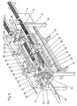
- Fig. 1 die perspektivische seitliche Draufsicht auf eine Vorrichtung nach der Erfindung mit einem hochschwenkbaren Andruckbalken,
- Fig. 2 eine rein schematische Teildarstellung der Anordnung nach Fig. 1 in Seitenansicht,
- Fig. 3 in perspektivischer Darstellung das Prinzip der Führung des Papieres zur Umhüllung des Stranges der scheibenförmigen Werkstücke in der Vorrichtung nach Fig. 1,
- Fig. 4 in perspektivischer Darstellung eine Einrichtung zum Beschneiden des Längsrandes des Papieres, welche in der Fig. 3 aus Übersichtlichkeitsgründen nicht wiedergegeben ist,
- Fig. 5 ein vereinfachtes Schaubild, aus welchem die Überführung der Stränge in die Einwickelstation ersichtlich ist,
- Fig. 6 das Teilbild eines Stranges in der Einwickelstation vor dem Einwickelvorgang,
- Fig. 7 in schematischer Darstellung die einzelnen Phasen a bis d des Einwickelvorganges,
- Fig. 8 in vergrößerter Darstellung die Seitenansicht der Einrichtung zum Aufbringen des Klebebandes auf ein Verschlußende des umhüllten Stranges,
- Fig. 9 die Anordnung nach Fig. 8 in einer anderen Position,
- Fig. 10 in vergrößerter perspektivischer Darstellung Vorrichtungen zum Anwalzen der Klebebandüberstände in zwei verschiedenen Positionen,
- Fig. 11 schematische Darstellungen zweier Phasen a und b zu Beginn und gegen Ende des Einwickelvorganges unter Bildung einer lose auf dem Strang angeordneten Umhüllung,
- Fig. 12 in vereinfachter Darstellung die Seitenansicht einer Rückführeinrichtung für die zwischen aufeinanderfolgende Stränge einschiebbaren Distanzstücke,
- Fig. 13 in schematischer Darstellung die Phasen a bis c des Anblasens und Anrollens der Klebebandüberstände,
- Fig. 14 eine perspektivische seitliche Draufsicht entsprechend der Fig. 1 auf eine andere Ausbildung der Vorrichtung, bei der eine Andrückrolle und die Papierleitbleche an heb- und senkbaren Tragarmen gehalten sind,
- Fig. 15 ein vereinfachtes der Fig. 5 entsprechendes Schaubild für die Anordnung nach Fig. 14 in Form einer Seitenansicht, aus welcher die Überführung der Stränge in die einzelnen Positionen ersichtlich ist.
- 1 is a side perspective top view of a device according to the invention with a pivotable pressure bar,
- 2 is a purely schematic partial representation of the arrangement of FIG. 1 in side view,
- 3 is a perspective view of the principle of guiding the paper for wrapping the strand of disc-shaped workpieces in the device according to FIG. 1,
- 4 is a perspective view of a device for trimming the longitudinal edge of the paper, which is not shown in FIG. 3 for reasons of clarity,
- 5 shows a simplified diagram from which the transfer of the strands into the wrapping station can be seen,
- 6 shows the drawing of a strand in the wrapping station before the wrapping process,
- 7 is a schematic representation of the individual phases a to d of the wrapping process,
- 8 is an enlarged side view of the device for applying the adhesive tape to a closure end of the wrapped strand,
- 9 shows the arrangement according to FIG. 8 in a different position,
- 10 shows an enlarged perspective view of devices for rolling on the adhesive tape protrusions in two different positions,
- 11 shows schematic representations of two phases a and b at the beginning and towards the end of the wrapping process, forming a sheathing loosely arranged on the strand,
- 12 shows a simplified representation of the side view of a return device for the spacers that can be inserted between successive strands,
- 13 shows a schematic representation of phases a to c of blowing and rolling on the adhesive tape protrusions,
- 14 is a perspective side plan view corresponding to FIG. 1 of another embodiment of the device, in which a pressure roller and the paper guide plates are held on lifting and lowering support arms,
- FIG. 15 shows a simplified diagram corresponding to FIG. 5 for the arrangement according to FIG. 14 in the form of a side view, from which the transfer of the strands into the individual positions can be seen.
Die in der Fig. 1 wiedergegebene Vorrichtung ist zum Anschluß an zwei parallel zueinander angeordnete Förderrinnen 1 und 2 vorgesehen, die jeweils mit einer Zähleinrichtung 3 und 4 für die längs der Förderrinnen 1 und 2 in die Vorrichtung zu überführenden scheiben förmigen Werkstücke ausgerüstet sind. In Falle des Ausführungsbeispieles sei angenommen, daß es sich bei den scheibenförmigen Werkstücken um Deckel handelt, welche in Stränge gleicher Anzahl unterteilt und in der Vorrichtung nach Fig. 1 in eine Umhüllung aus Papier mit endseitigem Verschluß dieser Umhüllung eingewickelt werden sollen.The device shown in FIG. 1 is intended for connection to two conveyor troughs 1 and 2 arranged parallel to one another, each with a
Die Vorrichtung nach Fig. 1 weist ein rahmen- bzw. tischförmiges Gestell 5 auf, an welchem in jeweiliger Verlängerung der Förderrinnen 1 und 2 für die Zuführung der einzuwickelnden Deckel Aufnahmerinnen 6 und 7 vorgesehen sind, welche in Längsrichtung des Rahmengestelles 5 verlaufen. An einer Querseite des Rahmengestelles 5 ist in diesem Beispiel der Fig. 1 ein höhenverschwenkbarer Andruckbalken 8 angelenkt, welcher sich in Längsrichtung mittig zwischen den Aufnahmerinnen 6 und 7 erstreckt und der in Richtung des Doppelpfeiles 9 von der in Fig. 1 dargestellten hochgeschwenkten Stellung in eine parallel zu den Aufnahmerinnen verlaufende abgesenkte Stellung überführbar ist. Zwischen den Aufnahmerinnen 6 und 7 sowie etwa mit diesen in gleicher Höhe und unterhalb des Andruckbalkens 8 ist die insgesamt mit 10 bezeichnete Einwickelstation bezeichnet, in welcher die jeweils aus den Aufnahmerinnen 6 und 7 entnommenen Deckelstränge in die Umhüllung eingewickelt werden. In der Darstellung der Fig. 1 ist ein Deckelstrang 11 in der Einwickelstation erkennbar.The device according to FIG. 1 has a frame-shaped or table-shaped
Die Einwickelstation 10 weist zwei um ihre Längsachse antreibbare Stützrollen 12 und 13 auf, welche bis auf die Drehbewegung ortsfest in dem Rahmengestell 5 gehalten sind. Zur Überführung der Deckelstränge von den Aufnahmerinnen 6 und 7 auf die antreibbaren Stüzrollen 12 und 13 der Einwickelstation 10 sind den Aufnahmerinnen beiderseits an dem jeweiligen Strang angreifende gegeneinander bewegbare Klemmschienen 14 und 15 zugeordnet. Die Klemmschienen 14 und 15 sind jeweils mit Betätigungseinrichtungen 16 und 17 verbunden, mit deren Hilfe sie in die Klemm- und Freigabestellung sowie in eine Position oberhalb der Aufnahmerinnen 6 bzw. 7 und aus dieser angehobenen Position in Richtung zur Einwickelstation 10 verschoben und dort bis auf die antreibbaren Stützrollen 11 und 12 abgesenkt werden können.The wrapping
Mit Hilfe der Betätigungseinrichtungen 16 und 17 sowie der damit verbundenen Klemmschienen 14 und 15 können somit die einzelnen Stränge 11 aus den Aufnahmerinnen entnommen, vorübergehend in eine angehobene Park- bzw. Wartestellung und aus dieser auf die antreibbaren Stützrollen 12 und 13 der Einwickelstation 10 überführt werden. Zu diesem Zweck sind die Betätigungseinrichtungen 16 und 17 in an sich bekannter Weise mit pneumatisch betätigbaren Antriebselementen ausgerüstet, welche die Hub- und seitliche Verschiebebewegung der Klemmschienen 14 und 15 bewirken.With the help of the
Die dem jeweiligen Deckelstrang 11 zugekehrten Seiten der Klemmschienen 14,15 sind zweckmäßig mit einer rutschsicheren und elastischen Beschichtung ausgerüstet, um alle Deckel eines Stranges sicher zu erfassen und unter Aufrechterhaltung der gegenseitigen Lage der Deckel in die Einwickelstation 10 überführen zu können.The sides of the clamping rails 14, 15 facing the
In der Fig. 5 ist schematisch der Bewegungsablauf der zwischen den Klemmschienen 14 und 15 gehaltenen Deckelstränge 11 dargestellt.5 schematically shows the sequence of movements of the
Es ist erkennbar, daß der im linken Teil der Fig. 5 von den Klemmschienen 14 und 15 erfaßte Deckelstrang 11 zunächst in die angehobene Stellung A überführt wird. Diese Stellung ist gleichzeitig eine Zwischen- und Wartestellung, während der die zugehörige Aufnahmerinne 6 bereits frei ist für die Aufnahme eines nächsten Deckelstranges. Aus der Position A kann der Deckelstrang 11 dann in die Position B oberhalb der Einwickelstation überführt werden, ehe von dort die Absenkung auf die antreibbaren Stützrollen 12 und 13 erfolgt. Der Bewegungsablauf ist durch Pfeile in der Fig. 5 angedeutet. Die Rückbewegung der Klemmschienen 14 und 15 erfolgt umgekehrt. Die Bewegung der im rechten Teil der Fig. 5 wiedergegebenen Klemmschienen 14 und 15 erfolgt analog, so daß im laufenden Wechsel oder aber in beliebiger Folge aus den Aufnahmerinnen 6 und 7 die Deckelstränge 11 entnommen und in die Einwickelstation 10 überführt werden können.It can be seen that the
Der Andruckbalken 8 ist gemäß Fig. 1 auf seiner Unterseite mit in seiner Längsrichtung verlaufenden Papierleitblechen 18 ausgerüstet, zwischen denen wenigstens eine ebenfalls in Längsrichtung des Andruckbalkens 8 verlaufende Andruckrolle 19 vorgesehen ist. In der abgesenkten Stellung des Andruckbalkens 8 erstreckt sich die Andruckrolle 19 parallel zu den antreibbaren Stützrollen 12 und 13.1, the
Ferner ist auf der Unterseite des Andruckbalkens 8 ein längs dieses Balkens verschiebbarer Schlitten 20 angeordnet, welcher mit in eine Schließ- und eine Spreizstellung überführbaren Faltfingern 21 ausgerüstet ist. Unterhalb des Andruckbalkens und in Höhe der Einwickelstation 10 ist an einer Stirnseite des Rahmengestelles 5 ein feststellbares Widerlager 22 vorge sehen, welches ebenfalls wie der Schlitten 20 mit Faltfingern 21 ausgerüstet ist.Furthermore, on the underside of the
Die Faltfinger 21 dienen in noch zu beschreibender Weise zur Bildung von Verschlußrosetten, die gegen Ende des Einwickelvorganges durch Überführung der Faltfinger 21 in die Schließstellung bei gleichzeitiger Rotationsbewegung des bereits in der Umhüllung befindlichen Stranges 11 entstehen.The
Im Bereich unterhalb der Einwickelstation 10 ist eine Vorratsrolle 23 des bahnförmigen Einwickelpapieres 24 in einer insgesamt mit 25 bezeichneten Abrolleinrichtung gehalten. Das bahnförmige Papier 24 wird mittels in der Fig. 1 nicht wiedergegebenen Abzugrollen von der Vorratsrolle 23 abgezogen und mit Hilfe einer später noch zu beschreibenden Zuführeinrichtung zwischen die antreibbaren Andruckrollen 12 und 13 geleitet sowie unter der Einwirkung der Papierleitbleche 18 und der Andruckrolle 19 um den jeweiligen Strang 11 in der Einwickelstation herumgewickelt.In the area below the wrapping
Um die Papierbahn 24 in die jeweils für einen Strang benötigten Abschnitte unterteilen zu können, ist eine Längsschneideinrichtung 26 vorgesehen, die in Fig. 1 nur schematisch als quer zur Papierbahn 24 verfahrbares Schneidrad dargestellt ist. Weiterhin ist zur Bildung des Verschlusses der um den jeweiligen Strang 11 gewickelten Papierbahn eine Beleimungseinrichtung 27 vorgesehen, die in dem dargestellten Beispiel als quer über die Papierbahn 24 verlaufender hin und her bewegbarer Düsenbalken 27 ausgebildet ist.In order to be able to divide the
Im Bereich des an dem Andruckbalken 8 vorgesehenen verfahrbaren Schlittens 20 ist in dem Rahmengestell 5 unmittelbar unterhalb der antreibbaren Stützrollen 12 und 13 ein weiterer Schlitten 28 auf einer entsprechenden längs des Rahmengestelles 5 verlaufenden Führung 28a gehalten, welcher in der abgesenkten Stellung des Andruckbalkens 8 mit dem darauf geführten Schlitten 20 koppelbar ist. Zu diesem Zweck ist der Schlitten 20 mit einem Koppelstift 29 ausgerüstet, welcher in eine entsprechende Bohrung 30 des Schlittens 28 eingreift.In the area of the
Der Schlitten 28 ist mit einer in der Fig. 1 aus Übersichtlichkeitsgründen nicht dargestellten Einrichtung zum Beschneiden des Randes des Einwickelpapieres 24 und mit einer insgesamt mit 31 bezeichneten Einrichtung zum Aufbringen des Verschlußklebebandes und eine zugehörige Schneideinrichtung ausgerüstet. Im Bereich des Widerlagers 22 ist ebenfalls eine in der Fig. 1 nicht wiedergegebene, jedoch während des Betriebes nicht verstellbare Einrichtung zum Aufbringen des Verschlußklebebandes mit zugehöriger Schneideinrichtung entsprechend der Einrichtung 31 vorgesehen.The
In schematischer Darstellung sind die Einrichtungen zum Aufbringen des Verschlußklebebandes mit den zugehörigen Schneideinrichtungen aus der Fig. 2 ersichtlich. In dieser Figur sind die mit Fig. 1 übereinstimmenden Teile jeweils auch mit den gleichen Bezugszeichen versehen.The devices for applying the sealing adhesive tape with the associated cutting devices can be seen from FIG. 2 in a schematic representation. In this figure, the parts corresponding to FIG. 1 are also provided with the same reference numerals.
In der Fig. 2 ist durch die Kolben-Zylinderanordnung 32 lediglich im Prinzip angedeutet, daß der Andruckbalken 8 längs des Doppelpfeiles 9 in die angehobene oder abgesenkte Stellung überführt und mit einem vorbestimmten Druck auf den einzuwickelnden Deckelstapel 11 zur Einwirkung gebracht werden kann.In Fig. 2 is indicated by the piston-
Hinsichtlich der Einrichtungen zum Aufbringen des Verschlußklebebandes zeigt die Fig. 2, daß an dem Schlitten 28 unterhalb der Einwickelstation 10 eine nach unten weisende Führungsstange 33 gehalten ist, welche einen heb- und senkbaren Träger 34 für eine Klebeverschlußbandrolle 35 aufnimmt. Von dem Träger 34 ragt eine parallel zu der Führungsstange 33 verlaufende Klebebandhalteplatte 36 auf, welche mit dem Träger 34 bei dessen Verschiebung längs der Führungsstange 33 in eine Position unmittelbar vor die Stirnseite 11a des bereits eingewickelten und mit einer Rosette versehenen Deckelstranges 11 überführbar und wieder in die in Fig. 2 wiedergegebene Stellung zurückfahrbar ist.With regard to the devices for applying the sealing adhesive tape, FIG. 2 shows that a downward-
In gleicher Weise ist im Bereich unterhalb des Widerlagers 22 eine aus den gleichen Teilen 33 bis 36 bestehende Einrichtung zum Aufbringen des Verschlußklebebandes vorgesehen, deren nach unten ragende Führungsstange 33 mit einem während des Betriebes der Vorrichtung auf der Führung 28a für den Schlitten 28 ortsfest gehaltenen Führungsstück 37 verbunden ist.In the same way, in the area below the
In der Fig. 2 sind die zum Abschneiden des Verschlußklebebandes vorgesehenen Schneideinrichtungen lediglich als quer zu dem Klebeband 39 verfahrbare Messer 38 angedeutet.2, the cutting devices provided for cutting off the sealing adhesive tape are only indicated as
Die Fig. 2 zeigt ferner, daß der Schlitten 28 mit einer Einrichtung zum Beschneiden des schlittenseitigen Randes der Papierbahn 24 ausgerüstet ist. Zu diesem Zweck ist in dem Schlitten 28 auf einer längs des Schlittens verlaufenden antreibbaren Welle 59 ein mitumlaufendes Schneidmesser 40 vorgesehen.FIG. 2 also shows that the
Weiterhin ist auf der Welle 59 ein mit dieser Welle umlaufendes Perforationsmesser 41 angeordnet, welches im Abstand und parallel zu dem beschnittenen Rand der Papierbahn 24 eine Rundum-Perforation 42 in die auf den Strang 11 gewickelte Papierbahn einschneidet.Furthermore, a
Schließlich zeigt die Fig. 2 noch, daß sowohl in dem an dem Andruckbalken 8 längsbeweglich gehaltenen Schlitten 20 als auch in dem Widerlager 22 je ein Druckbegrenzungstaster 43 geführt sind, wobei der Druckbegrenzungstaster 43 in dem Schlitten 20 den Vorschub des Schlittens 20 gegen den jeweils auf den antreibbaren Stützrollen 12 und 13 befindlichen Deckelstapel 11 bestimmt. Der Druckbegrenzungstaster 43 des ortsfesten Widerlagers 22 wird mit einem höheren Druck als der Druckbegrenzungstaster 43 des Schlittens 20 beaufschlagt, so daß er praktisch wie ein ortsfestes Widerlager wirkt.Finally, Fig. 2 shows that both in the
Durch den Druckbegrenzugstaster 43 in dem Schlitten 20 wird auf den Deckelstapel 11 unabhängig von dessen Länge jeweils der gleiche Druck ausgeübt, so daß die einzuwickelnden Deckelstapel jeweils die gleiche Packungsdichte aufweisen und bei größeren Dickentoleranzen der Deckel entsprechend längere bzw. kürzere Stapel 11 entstehen. Durch die Schneideinrichtung in dem Schlitten 28 wird dafür gesorgt, daß unabhängig von der Länge der jeweiligen Stapel der im Bereich des Schlittens 28 liegende Rand der Papierbahn 24 soweit beschnitten wird, daß noch eine Rosettenbildung möglich ist. Dabei wird auch die Perforationslinie 42 jeweils in gleichem Abstand von dem Ende des Deckelstapels eingeritzt.The
Die Schneideinrichtung zum Beschneiden des Randes der Papierbahn 24 ist in vergrößerter Darstellung in der Fig. 4, jedoch ohne den sie umgebenden bzw. sie aufnehmenden Schlitten 28 wiedergegeben. Auch hier sind wiederum die gleichen Teile mit gleichen Bezugszeichen versehen.The cutting device for trimming the edge of the
Man erkennt, daß die Papierbahn 24 zwischen zwei angetriebenen Wellen 59 und 59a hindurchgeführt ist, wobei zum Antrieb der Wellen 59 und 59a ein Zahnriementrieb 44 dient. Der zugehörige Antriebsmotor kann am oder im Schlitten 28, beispielsweise in der Form eines Hydraulmotors, vorgesehen sein.It can be seen that the
Die Zuführung der Papierbahn 24 von der Vorratsrolle 23 zu dem Deckelstapel 11 ist schematisch in vergrößerter Form in Fig. 3 gezeigt.The feeding of the
Die Bahn 24 ist über eine Umlenkrolle 45 sowie zwischen angetriebenen zusammenwirkenden Zugrollen 46 und 47 und weiteren Rollen 46a und 47a geführt. Zwischen den vorgenannten Rollenpaaren sind in der Zeichnung nicht wiedergegebene Leitbleche vorgesehen.The
Die vorgesehene Schneideinrichtung zum Abschneiden der Bahnabschnitte weist einen mit dem Schneidrad 26 zusammenwirkenden Schneidbalken 48 auf.The cutting device provided for cutting off the web sections has a cutting
Die Fig. 3 läßt ferner deutlich die Leimauftragseinrichtung in Form des Düsenbalkens 27 mit den daran gehaltenen Beleimungsdüsen 27a erkennen.3 also clearly shows the glue application device in the form of the
Die jeweils in die Einwickelstation 10 überführten Deckelstränge 11 werden nach ihrer Überführung in die Einwickelstation 10 bis zur Anlage der Druckbegrenzungstaster 43 an ihren Stirnseiten durch Blasdüsen beaufschlagt, wie dies in Fig. 6 für einen auf den antreibbaren Stützrollen 12 und 13 befindlichen Strang 11 durch die Düsen 65 dargestellt ist. Die Düsen 65 können dabei an dem Andruckbalken längsverschieblich gehalten sein, um sie auf die jeweilige Länge des Stranges 11 einzustellen.The
Die Bildung der Rosetten an den Enden der von der Papierbahn 24 gebildeten Umhüllung ist aus der Fig. 7 ersichtlich, welche rein schematisch die einzelnen Phasen des Einwickelns wiedergibt.The formation of the rosettes at the ends of the wrapping formed by the
In der Phase nach a ist der Deckelstrang 11 gemäß der Darstellung der Fig. 6 an den Stirnseiten von den Düsen 65 so beaufschlagt, daß die Deckel an den Enden nicht umfallen können.In the phase after a, the
In der Phase gemäß b ist der Schlitten 20 bei gespreizten Faltfingern 21 mit seinem vorgeschobenen Druckbegrenzungstaster 43 gegen den Strang 11 vorgefahren und hat diesen gegen den Druckbegrenzungstaster 43 des Widerlagers 22 gedrückt, so daß er in die richtige Position in bezug auf die Papierbahn 24 überführt und unter Aufrechterhaltung eines axialen Druckes durch Zuführung der Papierbahn 24 umhüllt wird, wie dies in der Phase c dargestellt ist. Während der weiteren Rotation des bereits mit der umfänglichen Umhüllung versehenen Deckelstranges 11 werden nunmehr die Faltfinger 21 gemäß der Phase d in die Schließstellung überführt, wobei die Faltfinger mit dem stirnseitigen Überstand der Umhüllung so zusammenwirken, daß eine Rosette gefaltet wird. Im letzten Teil der Phase der Zusammenführung der Faltfinger 21 werden die Druckbegrenzungstaster 43 in ihre Ausgangsposition zurückverfahren.In the phase according to b, the
Die nachfolgende Aufbringung des Verschlußklebebandes 39 ist in Form einer Teildarstellung aus der Fig. 2 in vergrößerter Darstellung und für zwei unterschiedliche Positionen der Klebebeband-Halteplatten 36 in den Fig. 8 und 9 wiedergegeben.The subsequent application of the sealing
Die Fig. 8 und 9 zeigen dabei die im Bereich des Widerlagers 22 in der Fig. 2 dargestellte Einrichtung zum Aufbringen des Verschlußklebebandes 39.8 and 9 show the device for applying the sealing
In der Fig. 8 ist die Klebeband-Halteplatte 36 in ihrer unteren Ausgangsstellung wiedergegeben. Die Klebeband-Halteplatte 36 weist Düsenöffnungen 36a auf, die mit einem Sammelkanal 36b verbunden sind, der seinerseits an eine Leitung 36c angeschlossen ist, über die eine Druck- bzw. Saugluftquelle angeschlossen werden kann.8, the adhesive
In der in Fig. 8 wiedergegebenen Stellung der Verschlußklebeband-Halteplatte 36 erfolgt eine Besaugung der Düsenöffnungen 36a, so daß der vor der Halteplatte 36 befindliche Abschnitt des Verschlußklebebandes 39 an die Halteplatte 36 angepreßt wird. Das Verschluß-Klebeband 39 ist auf seiner der Halteplatte 36 abgekehrten Seite mit Klebstoff beschichtet. Der sich oberhalb der Halteplatte 36 erstreckende Abschnitt des Verschlußklebebandes 39 haftet mit seiner Klebstoffschicht an der stirnseitigen Rosette der Umhüllung des Deckelstapels 11. Durch Betätigung der als bewegliches Messer 38 dargestellten Schneideinrichtung wird der oberhalb der Halteplatte 36 befindliche Abschnitt des Verschlußklebebandes 39 abgeschnitten und die überstehenden Enden dieses Abschnittes werden auf die Umhüllung des Stapels 11 umgelegt und dort in noch zu beschreibender Weise angedrückt. Während der Aufbringung des Verschlußklebebandes 39 befindet sich der mit der Umhüllung versehene Deckelstrang 11 in Ruhe, d.h. er wird nicht mehr von den antreibbaren Stützrollen 12 und 13 in Rotationsbewegung versetzt. Nach dem Aufbringen des Verschlußklebebandes 39 auf die stirnseitigen Enden der umhüllten Deckelstapel 11 wird der jeweils fertiggestellte Deckelstapel in Längsrichtung aus der Einwickelstation 10 aus der Vorrichtung nach Fig. 1 herausgeschoben und gelangt dabei gemäß der Fig. 1 auf eine Ausschubrinne 66.In the position of the sealing
Nachdem der nächste Deckelstapel 11 in der Einwickelstation mit seiner Umhüllung einschl. der Rosetten gebildet ist, wird die Klebeband-Halteplatte 36 aus der in Fig. 8 wiedergegebenen Stellung unter Aufrechterhaltung der Saugwirkung an den Düsenöffnungen 36a in die in Fig. 9 wiedergegebenen Position überführt und in dieser Position dann statt der Besaugung der Düsenöffnungen 36a eine Beaufschlagung mit Druckluft vorgenommen, wie dies durch die Pfeile in der Fig. 9 angedeutet ist. Auf diese Weise wird der vor der Halteplatte 36 befindliche Abschnitt des Verschlußklebebandes 39 gegen die Rosette gedrückt und fixiert diese. Das obere Ende des Klebebandabschnittes 39 wird dabei bereits in Richtung auf den Deckelstrang umgelegt. Bei der nun folgenden Abwärtsbewegung der Halteplatte zur Überführung in die Position gemäß Fig. 8 wird ein weiterer Abschnitt des Klebebandes 39 von der Rolle 35 abgezogen und der vor der Halteplatte 36 befindliche Abschnitt wieder über die Düsenöffnungen 36a mit Saugluft beaufschlagt, wie dies im Zusammenhang mit der Fig. 8 bereits beschrieben wurde.After the
Zum Anrollen der überstehenden Enden des Klebebandes 39 an die Umfangsfläche der Umhüllung des Deckelstranges 11 können an dem Andruckbalken 8 bzw. an dem verfahrbaren Schlitten 20 von oben nach unten verschwenk bare Träger 67 gemäß Fig. 10 vorgesehen sein mit diametral über die Strangenden verfahrbaren Rollen 68, welche an einem Schlitten 69 gehalten sind, der seinerseits längs des Trägers 67 hin und her verfahrbar ist.To roll the protruding ends of the
In der Fig. 10 ist im oberen Teil die Phase a, nämlich die Ausgangsstellung der federnden Andruckrollen 68, gezeigt und im unteren Teil die Phase b, bei der die Andruckrollen 68 die überstehenden Enden des Verschlußklebebandes 39 auf die Umfangsfläche der Umhüllung des Stranges 11 aufgewalzt haben.10, phase a, namely the starting position of the
Statt dieser beschriebenen Art des Anwalzens der Enden des Verschlußklebebandes 39 kann gemäß Fig. 13 auch vorgesehen sein, daß die überstehenden Enden des Klebebandes 39 über zusätzliche Blasdüsen 50 beaufschlagt werden, so daß sie aus der in Fig. 13 wiedergegebenen Phase a über die Phase b in die Stellung gemäß Phase c überführt werden und in Haftberührung mit der Umhüllung des Stranges 11 gelangen. Das Anwalzen kann dann in der Phase c durch eine erneute Rotationsbewegung des Deckelstranges 11 mittels der antreibbaren Stützrollen 12 und 13 erfolgen.Instead of this described way of rolling the ends of the sealing
Wie man eine umfänglich lockere Umhüllung der Deckelstränge 11 erzielt, die wünschenswert ist, um die Deckel nach Öffnen der Umhüllung aus dieser leicht entnehmen zu können, ist in der Fig. 11 in schematischer Darstellung veranschaulicht.A schematic representation of how the circumferentially loose covering of the
In der Phase a im linken Teil der Fig. 11 ist der Beginn des Einwickelns des Stranges 11 wiedergegeben, in dem rechten Teil die Phase b unmittelbar vor Beendigung des Einwickelvorganges.In phase a in the left part of FIG. 11 the start of the winding of the
Der Deckelstrang 11 liegt in der Einwickelstation 10 auf den antreibbaren Stützrollen 12 und 13, auf die er durch die Druckrolle 19 des abgesenkten Andruckbalkens 8 gedrückt wird. Die Papierbahn 24 zum Einwickeln des Stapels 11 wird längs der in Fig. 11 wiedergegebenen Führungsbleche 70 und 71 sowie durch das antreibbare Rollenpaar 46a und 47a in den Spaltraum zwischen der antreibbaren Stützrolle 12 und dem Stapel 11 geleitet.The
Der Stapel 11 ist bei abgesenktem Andruckbalken 8 von den in radialem Abstand zu dem Stapel verlaufenden Papierleitblechen 18 umgeben, wobei auch im Bereich unterhalb der andrückbaren Stützrollen 12 und 13 ein Papierleitblech 18 vorgesehen ist.When the
Beim Einwickelvorgang gleitet die zugeführte Papierbahn 24 im Bereich außerhalb der Stütz- bzw. Andruckrollen 12,13 und 19 längs der Innenwandflächen der Papierleitbleche 18, so daß eine lose Umhüllung entsteht, wie sie in der Phase b im rechten Teil der Fig. 11 wiedergegeben ist.During the wrapping process, the supplied
In der dargestellten Phase a des linken Teiles der Fig. 11 ist der Zeitpunkt des Leimauftrages auf den endseitigen Rand der Papierbahn angedeutet, welcher mit Hilfe des bereits beschriebenen Düsenbalkens 27 bewerkstelligt wird.In the phase a shown in the left part of FIG. 11, the time of applying the glue to the end edge of the paper web is indicated, which is accomplished with the aid of the
Um die einzelnen aus den Förderrinnen 1 und 2 der Vorrichtung zugeführten Deckelstapel 11 voneinander zu trennen, damit diese einen Abstand von den nachfolgenden Deckeln des nächsten Stapels beibehalten, ist eine von des Zähleinrichtungen 3 und 4 steuerbare Vorschubeinrichtung für den aus den abgezählten Deckeln bestehenden Strang 11 in Verbindung mit einer Einrich tung zum Einlegen von Distanzstücken vorgesehen, welche schematisch in Fig. 12 und teilsweise auch in der Fig. 1 wiedergegeben ist.In order to separate the individual lid stacks 11 fed from the conveyor troughs 1 and 2 of the device so that they maintain a distance from the subsequent lids of the next stack, a feed device for the
Gemäß Fig. 12 ist die dort wiedergegebene Zähleinrichtung 3 mit einer von ihr steuerbaren Vorschubeinrichtung 51 versehen, welche bei Erreichen der Sollzahl die Deckel eines Stapels 11 in der angedeuteten Weise vorschiebt, so daß eine Lücke 52 zwischen dem Stapel 11 und den nachfolgenden Deckeln entsteht. In diese Lücke werden ein oder mehrere zylinderförmige Distanzstücke eingebracht, welche im Durchmesser kleiner sind als die Deckel, so daß sie bei Überführung des Deckelstapels 11 aus der Aufnahmerinne 6 bzw. 7 in die Einwickelstation 10 nicht mit erfaßt werden. Die somit in der Aufnahmerinne 6 bzw. 7 verbleibenden Distanzstücke 53 werden vom Ende der Aufnahmerinne 6 bzw. 7 wieder in den Bereich der Lücke 52 zurückgeführt. Zu diesem Zweck ist eine oberhalb im Abstand parallel zu der jeweiligen Aufnahmerinne 6 bzw. 7 verlaufende Rohrleitung 54 vorgesehen, welche mit Verbindungsschächten 55 und 56 verbunden ist. Über eine Kolben-Zylinderanordnung 57 werden die am Ende der Aufnahmerinne 6 bzw. 7 ankommenden Distanzstücke 53 in die Rohrleitung 54 überführt und dort durch eine weitere Kolben-Zylinderanordnung 58 in Richtung zum Anfang der Aufnahmerinne 6 bzw. 7 weitergefördert, wie dies durch Pfeile angedeutet ist. In dem Verbindungsschacht 56 sind steuerbare Aufhalter in Form von Kolben-Zylinderanordnungen vorgesehen, die von der Vorschubeinrichtung 51 betätigt werden, so daß nach der Bildung der Lücke 52 eine oder mehrere Distanzstücke 53 zum Einfallen in die Lücke 52 freigegeben werden.According to FIG. 12, the
Die in der Fig. 2 schematisch wiedergegebene Einrichtung ist teilweise in der Fig. 1 oberhalb der Aufnahmerinne 6 ebenfalls erkennbar.The device shown schematically in FIG. 2 is also partially recognizable in FIG. 1 above the receiving
Die Fig. 14 und 15 zeigen eine Variante der Anordnung nach der Fig. 1, wobei die Abweichung im wesentlichen darin besteht, daß bei der Anordnung nach den Fig. 14 und 15 kein Andruckbalken mit den daran gehaltenen Elementen vorgesehen ist. In den Fig. 14 und 15 sind die mit den übrigen Figuren übereinstimmenden Teile jeweils auch mit gleichen Bezugszeichen versehen.14 and 15 show a variant of the arrangement according to FIG. 1, the difference essentially consisting in the fact that in the arrangement according to FIGS. 14 and 15 there is no pressure bar with the elements held thereon. 14 and 15, the parts corresponding to the other figures are also provided with the same reference numerals.
Statt des in Fig. 1 wiedergegebenen Andruckbalkens 8 mit den daran gehaltenen Andruckrollen 19 und Papierleitblechen 18 sind in der Ausführung nach den Fig. 14 und 15 heb- und senkbare Tragarme 60 vorgesehen, an denen die Andrückrolle 19 und die Papierleitbleche 18 gehalten sind. Die Tragarme 60 sind nach Art von Auslegerarmen an Hub- bzw. Führungsstangen 62 gehalten, die in dem dargestellten Beispiel über Zwischenstücke 63 an der parallel zu der Aufnahmerinne 6 verlaufenden Rohrleitung 54 für die Rückführung der Distanzstücke 53 befestigt sind. Die Tragarme 60 erstrecken sich nach Art von Auslegern bis über die Einwickelstation 10 und sind in Richtung der dargestellten Doppelpfeile entlang der lotrechten Stangen oder gemeinsam mit diesen so weit höhenverfahrbar, daß in der abgesenkten Stellung die Andrückrolle 19 auf dem in der Einwickelstation 10 befindlichen Deckelstrang 11 aufliegt und in der angehobenen Stellung die Zuführung eines weiteren Deckelstranges aus einer der Aufnahmerinnen 6 bzw. 7 mittels der gegeneinander bewegbaren Klemmschienen 14 und 15 in der zuvor beschriebenen Weise nicht behindert wird.Instead of the
Die an den Tragbalken gehaltenen Papierleitbleche 18 sind bei der Vorrichtung nach den Fig. 14 und 15 gleichzeitig als Greifschalen ausgebildet und mit einer in den Figuren nicht wiedergegebenen Betätigungseirichtung verbunden, so daß sie aus einer Stellung, in der sie den einzuwickelnden Strang mit Abstand umgeben, in eine Klemmstellung überführt werden können, um den jeweilig in der Einwickelstation 10 eingewickelten und mit den stirnseitig aufgebrachten Verschlußbändern versehenen Strang zu erfassen und bei der Aufwärtsbewegung der Tragarme 60 in die angehobene Position zu überführen. Da in dieser angehobenen Position das Anwalzen der Verschlußklebebandenden erfolgen soll, sind fluchtend mit dem Strang in seiner angehobenen Position die in der Fig. 1 schwenkbar an dem Andruckbalken 8 gehaltenen längsverfahrbaren federnden Rollen 68 in einer ortsfesten Schlittenführung 64 gehalten und können mittels eines in der Zeichnung nicht wiedergegebenen Antriebes in Richtung der Doppelpfeile mit ihren federnden Rollen 68 in der bereits früher beschriebenen Weise zum Anwalzen der Verschlußklebebandenden über die Strangenden und zurück verfahren werden.The
Das Anwalzen der Verschlußbandklebebandenden erfolgt somit bei der Anordnung nach den Fig. 14 und 15 nicht mehr in der Einwickelstation 10, sondern in einer Position des eingewickelten Deckelstranges oberhalb dieser Einwickelstation. Hierdurch kann die Einwickelstation bereits während des Anwalzens der Verschlußklebebandenden mit einem neuen Deckelstrang beschickt werden.In the arrangement according to FIGS. 14 and 15, the closure tape adhesive tape ends are no longer rolled in the wrapping
Um den mit dem aufgewalzten Verschlußklebeband versehenen Deckelstrang zu entnehmen, ohne den nächsten Einwikkelvorgang zu behindern, sind unter den in der angehobenen Stellung befindlichen Deckelstrang verschwenkbare Laschen 61 vorgesehen, über die nach der Freigabe des Deckelstranges durch Spreizung der Papierleitbleche 18 der Strang in die nunmehr abweichend von der Fig. 1 seitlich und oberhalb der Einwickelstation vorgesehene Ausschubrinne 66 rollen kann, aus der er mittels einer nicht dargestellten Ausschubvorrichtung weiterbefördert wird.In order to remove the cover strand provided with the rolled-up sealing tape without interfering with the next wrap-in process, swivels are pivotable under the cover strand which is in the raised
Der in Fig. 1 an dem Andruckbalken vorgesehene verfahrbare Schlitten 20 ist bei der Ausführung nach den Fig. 14 und 15 baulich mit dem Schlitten 28 vereint und bildet den in Fig. 14 wiedergegebenen Bauteil 20a, welcher wie der Schlitten 20 mit den Faltfingern 21 und einem Druckbegrenzungstaster ausgerüstet ist, wie dies im Zusammenhang mit dem Schlitten 20 bereits beschrieben wurde.The
Die Fig. 15 zeigt in schematischer Darstellung die obere Position der Tragarme 60 sowie die Anordnung der geneigten Laschen 61 und der seitlich oberhalb der Einwickelstation 10 vorgesehenen Ausschubrinne. In dem dargestellten Beispiel sind die geneigten Laschen 61 an der Ausschubrinne 66 angelenkt. Man erkennt aus der Fig. 15, daß bei angehobener Stellung der Tragarme 60 die Einwickelstation 10 ohne weiteres mit einem neuen Strang aus einer der Aufnahmerinnen 6 bzw. 7 beschickt werden kann.15 shows a schematic representation of the upper position of the
Soweit nicht vorstehend eine abweichende Arbeitsweise und Funktion der Vorrichtung nach den Fig. 14 und 15 beschrieben ist, arbeitet diese in gleicher Weise wie die Vorrichtung nach der Fig. 1 und den zugehörigen Einzeldarstellungen.Unless a different mode of operation and function of the device according to FIGS. 14 and 15 is described above, it works in the same way as the device according to FIG. 1 and the associated individual representations.
Über eine in der Zeichnung nicht wiedergegebenen Elektronik werden die einzelnen Bewegungsabläufe und ihre Folge gesteuert, wobei für den Antrieb der einzelnen zu bewegenden Elemente der Vorrichtung überwiegend Kolben-Zylinderanordnungen vorgesehen sind, ohne daß die Vorrichtung jedoch auf die Verwendung dieser Antriebselemente beschränkt ist.The individual movement sequences and their sequence are controlled by electronics not shown in the drawing, piston-cylinder arrangements being predominantly provided for driving the individual elements of the device to be moved, but the device is not restricted to the use of these drive elements.
Claims (14)
Applications Claiming Priority (2)
| Application Number | Priority Date | Filing Date | Title |
|---|---|---|---|
| DE19873729271 DE3729271A1 (en) | 1987-09-02 | 1987-09-02 | DEVICE FOR PACKING CYLINDRICAL STRINGS FROM A VARIETY OF DISC-SHAPED WORKPIECES |
| DE3729271 | 1987-09-02 |
Publications (2)
| Publication Number | Publication Date |
|---|---|
| EP0305956A2 true EP0305956A2 (en) | 1989-03-08 |
| EP0305956A3 EP0305956A3 (en) | 1990-03-21 |
Family
ID=6335030
Family Applications (1)
| Application Number | Title | Priority Date | Filing Date |
|---|---|---|---|
| EP88114083A Withdrawn EP0305956A3 (en) | 1987-09-02 | 1988-08-30 | Device for packaging cylindrical strands composed of a plurality of discoid pieces |
Country Status (4)
| Country | Link |
|---|---|
| US (1) | US4848059A (en) |
| EP (1) | EP0305956A3 (en) |
| CA (1) | CA1297777C (en) |
| DE (1) | DE3729271A1 (en) |
Cited By (3)
| Publication number | Priority date | Publication date | Assignee | Title |
|---|---|---|---|---|
| EP0495580A1 (en) * | 1991-01-16 | 1992-07-22 | Fleetwood Systems, Inc. | Multi-lane infeed counter/bagger |
| FR2715371A1 (en) * | 1994-01-21 | 1995-07-28 | Sppr | Method of automatically wrapping foie gras under aluminium@ foil |
| EP0688719A1 (en) * | 1994-06-20 | 1995-12-27 | Pakenso Oy | A method and an apparatus for packing cardboard end covers of paper rolls and a package |
Families Citing this family (12)
| Publication number | Priority date | Publication date | Assignee | Title |
|---|---|---|---|---|
| US5175980A (en) * | 1988-09-30 | 1993-01-05 | Sardee Industries, Inc. | Apparatus and method for packaging groups of articles |
| US4967537A (en) * | 1989-10-26 | 1990-11-06 | Adolph Coors Company | Apparatus for packaging articles |
| US5005340A (en) * | 1989-12-21 | 1991-04-09 | Fleetwood Systems, Inc. | Apparatus for inspecting and packaging can ends |
| US5471822A (en) * | 1991-09-30 | 1995-12-05 | Coors Brewing Company | Apparatus and method for packaging articles |
| US5617704A (en) * | 1992-09-15 | 1997-04-08 | Ferag Ag | Method of forming a tubular pack of printed products with a transparent foil cover |
| US5533321A (en) * | 1995-08-09 | 1996-07-09 | Lamb-Grays Harbor Co. | Method and apparatus for wrapping, crimping and heading paper rolls at a single station |
| US5685129A (en) * | 1996-06-14 | 1997-11-11 | Metal Container Corporation | Automatic can lid bag sealer |
| ES2246638B1 (en) * | 2003-05-06 | 2007-04-01 | Taller Autorema, S.L. | AUTOMATIC BASIC PACKING MACHINE FOR BASIC AND EASY OPENING BAGS IN SELF-BOLLING PAPER BAGS. |
| PT1559650E (en) * | 2004-01-23 | 2007-06-01 | Taller Autorema S L | Automatic bagging machine of lids in self-adhesive bags |
| NL1028793C2 (en) * | 2005-04-18 | 2006-10-20 | Celema B V | Device for transporting a series of loose objects placed one behind the other in the vertical direction. |
| WO2009057985A1 (en) * | 2007-11-01 | 2009-05-07 | Technicolor Mexicana, S. De R. L. De C. V. | Packaging machine and method for packaging optical disks with stretch film |
| CN110194287A (en) * | 2019-06-10 | 2019-09-03 | 昆山市健侑科技有限公司 | Automatic film rolling machine |
Citations (4)
| Publication number | Priority date | Publication date | Assignee | Title |
|---|---|---|---|---|
| FR462561A (en) * | 1912-09-19 | 1914-01-30 | Sapal Plieuses Automatiques | Machine for packaging washer-shaped bodies or cylindrical objects |
| DE719595C (en) * | 1939-05-11 | 1942-06-18 | Heinrich Dahlhaus | Method and device for packing disc-shaped objects, such as tablets made of sugar, peppermint, or the like. |
| EP0141938A1 (en) * | 1983-09-26 | 1985-05-22 | KARGES-HAMMER-MASCHINEN GmbH & Co. KG | Container and method and device for the transport of can end stacks in this container |
| EP0206374A2 (en) * | 1985-05-28 | 1986-12-30 | Thomassen & Drijver-Verblifa N.V. | An apparatus for packing a row of lids and the completed package |
Family Cites Families (10)
| Publication number | Priority date | Publication date | Assignee | Title |
|---|---|---|---|---|
| DE501574C (en) * | 1927-07-16 | 1930-07-07 | Mills Novelty Company | Machine for wrapping small items |
| US3899864A (en) * | 1972-12-15 | 1975-08-19 | Laurel Bank Machine Co | Coin wrapping apparatus |
| JPS5819530B2 (en) * | 1978-09-22 | 1983-04-19 | ロ−レルバンクマシン株式会社 | How to set wrapping paper on coin wrapping machine |
| US4221103A (en) * | 1978-11-20 | 1980-09-09 | Laurel Bank Machine Co., Ltd. | Packaging paper cutting mechanism for coin packaging machine |
| US4417435A (en) * | 1979-02-24 | 1983-11-29 | Daiwa Can Company | Apparatus for automatically packing end closures for cans in paper bags |
| US4395864A (en) * | 1981-01-28 | 1983-08-02 | American Can Company | Apparatus for the automatic counting and bagging of can ends |
| US4537550A (en) * | 1983-09-29 | 1985-08-27 | Fleetwood Systems, Inc. | Automatic stack developing and loading system |
| JPS61152518A (en) * | 1984-12-25 | 1986-07-11 | 友和産業株式会社 | Packer for end surface of cylindrical article |
| US4651500A (en) * | 1985-02-14 | 1987-03-24 | Valley Tissue Packaging, Inc. | Method and apparatus for wrapping rolls of paper |
| JPH059284Y2 (en) * | 1985-03-20 | 1993-03-08 |
-
1987
- 1987-09-02 DE DE19873729271 patent/DE3729271A1/en not_active Withdrawn
-
1988
- 1988-08-30 EP EP88114083A patent/EP0305956A3/en not_active Withdrawn
- 1988-08-31 CA CA000576199A patent/CA1297777C/en not_active Expired - Lifetime
- 1988-09-02 US US07/240,256 patent/US4848059A/en not_active Expired - Fee Related
Patent Citations (4)
| Publication number | Priority date | Publication date | Assignee | Title |
|---|---|---|---|---|
| FR462561A (en) * | 1912-09-19 | 1914-01-30 | Sapal Plieuses Automatiques | Machine for packaging washer-shaped bodies or cylindrical objects |
| DE719595C (en) * | 1939-05-11 | 1942-06-18 | Heinrich Dahlhaus | Method and device for packing disc-shaped objects, such as tablets made of sugar, peppermint, or the like. |
| EP0141938A1 (en) * | 1983-09-26 | 1985-05-22 | KARGES-HAMMER-MASCHINEN GmbH & Co. KG | Container and method and device for the transport of can end stacks in this container |
| EP0206374A2 (en) * | 1985-05-28 | 1986-12-30 | Thomassen & Drijver-Verblifa N.V. | An apparatus for packing a row of lids and the completed package |
Cited By (4)
| Publication number | Priority date | Publication date | Assignee | Title |
|---|---|---|---|---|
| EP0495580A1 (en) * | 1991-01-16 | 1992-07-22 | Fleetwood Systems, Inc. | Multi-lane infeed counter/bagger |
| FR2715371A1 (en) * | 1994-01-21 | 1995-07-28 | Sppr | Method of automatically wrapping foie gras under aluminium@ foil |
| EP0688719A1 (en) * | 1994-06-20 | 1995-12-27 | Pakenso Oy | A method and an apparatus for packing cardboard end covers of paper rolls and a package |
| US5706945A (en) * | 1994-06-20 | 1998-01-13 | Pakenso Oy | Method and an apparatus for packing cardboard end covers of paper rolls and a package |
Also Published As
| Publication number | Publication date |
|---|---|
| US4848059A (en) | 1989-07-18 |
| CA1297777C (en) | 1992-03-24 |
| EP0305956A3 (en) | 1990-03-21 |
| DE3729271A1 (en) | 1989-03-23 |
Similar Documents
| Publication | Publication Date | Title |
|---|---|---|
| DE3243994C2 (en) | Winding machine for winding a lengthwise split web | |
| DE3141413C2 (en) | Winding machine for winding a web | |
| DE2930474C2 (en) | Double roller developing machine | |
| DE1278327B (en) | Device for stacking and wrapping coins, tokens or the like in a film | |
| EP0305956A2 (en) | Device for packaging cylindrical strands composed of a plurality of discoid pieces | |
| CH649267A5 (en) | METHOD AND DEVICE FOR INSERTING AT LEAST ONE INSERT IN PRINTED PRODUCTS. | |
| WO1980001794A1 (en) | Device for roller change | |
| DE1532830B1 (en) | Method and machine for the continuous production of carrier bags | |
| DE3308059C2 (en) | ||
| EP0143930B1 (en) | Method and apparatus for manufacturing brushes | |
| EP0432592B1 (en) | Device for packaging cigarettes | |
| DE4122692A1 (en) | WINDING MACHINE FOR ESSENTIAL PARALLEL FLAT BOX-SHAPED ELEMENTS | |
| DE2624812A1 (en) | WRAPPING MACHINE | |
| DE60200291T2 (en) | Wrapping machine with flanks for carrying cross-dowels moving along a closed path | |
| AT404538B (en) | DEVICE FOR PRODUCING WRAPS FROM DOUGH SHEETS AND DIVISION SHEETS | |
| DE3505597A1 (en) | DEVICE FOR FORMING ROWS IN DISTANCE | |
| DE1112392B (en) | Device for feeding winding cores in a paper winding machine | |
| DE1561434C3 (en) | Process for the continuous manufacture of carrier bags or pouches with two handles and a machine for carrying out the process | |
| DE2629381C3 (en) | Process for the continuous production of tampon blanks and device for carrying out the process | |
| DE2913538A1 (en) | METHOD AND DEVICE FOR LABELING AND / OR FILLING BOTTLES | |
| DE2414564C3 (en) | Device for the transverse cutting of continuously running material webs perforated at intervals to form AbreiBschwächungsUnien transversely | |
| EP1451087B1 (en) | Device for continuously winding webs | |
| DE4035143C2 (en) | Double carrier roller winding machine for the continuous winding of a web of material passed from below through the nip of two carrier rollers of an upper pair of carrier rollers or of several adjacent strips of plastic, fleece, paper or the like. | |
| DE2537692A1 (en) | Automatic packaging of bottles into folding boxes - using offset rows of bottles moving on conveyor and guided with carton strips inserted between rows | |
| DE449485C (en) | Method and device for the production of flycatchers in roll form |
Legal Events
| Date | Code | Title | Description |
|---|---|---|---|
| PUAI | Public reference made under article 153(3) epc to a published international application that has entered the european phase |
Free format text: ORIGINAL CODE: 0009012 |
|
| AK | Designated contracting states |
Kind code of ref document: A2 Designated state(s): BE DE FR GB IT LU NL SE |
|
| PUAL | Search report despatched |
Free format text: ORIGINAL CODE: 0009013 |
|
| AK | Designated contracting states |
Kind code of ref document: A3 Designated state(s): BE DE FR GB IT LU NL SE |
|
| 17P | Request for examination filed |
Effective date: 19900625 |
|
| 17Q | First examination report despatched |
Effective date: 19920512 |
|
| STAA | Information on the status of an ep patent application or granted ep patent |
Free format text: STATUS: THE APPLICATION IS DEEMED TO BE WITHDRAWN |
|
| 18D | Application deemed to be withdrawn |
Effective date: 19921229 |