EP0303676B1 - Teilung für wegmessapparat - Google Patents
Teilung für wegmessapparat Download PDFInfo
- Publication number
- EP0303676B1 EP0303676B1 EP88902508A EP88902508A EP0303676B1 EP 0303676 B1 EP0303676 B1 EP 0303676B1 EP 88902508 A EP88902508 A EP 88902508A EP 88902508 A EP88902508 A EP 88902508A EP 0303676 B1 EP0303676 B1 EP 0303676B1
- Authority
- EP
- European Patent Office
- Prior art keywords
- marks
- scale
- read head
- information
- signal
- Prior art date
- Legal status (The legal status is an assumption and is not a legal conclusion. Google has not performed a legal analysis and makes no representation as to the accuracy of the status listed.)
- Expired
Links
Images
Classifications
-
- G—PHYSICS
- G01—MEASURING; TESTING
- G01D—MEASURING NOT SPECIALLY ADAPTED FOR A SPECIFIC VARIABLE; ARRANGEMENTS FOR MEASURING TWO OR MORE VARIABLES NOT COVERED IN A SINGLE OTHER SUBCLASS; TARIFF METERING APPARATUS; MEASURING OR TESTING NOT OTHERWISE PROVIDED FOR
- G01D5/00—Mechanical means for transferring the output of a sensing member; Means for converting the output of a sensing member to another variable where the form or nature of the sensing member does not constrain the means for converting; Transducers not specially adapted for a specific variable
- G01D5/12—Mechanical means for transferring the output of a sensing member; Means for converting the output of a sensing member to another variable where the form or nature of the sensing member does not constrain the means for converting; Transducers not specially adapted for a specific variable using electric or magnetic means
- G01D5/244—Mechanical means for transferring the output of a sensing member; Means for converting the output of a sensing member to another variable where the form or nature of the sensing member does not constrain the means for converting; Transducers not specially adapted for a specific variable using electric or magnetic means influencing characteristics of pulses or pulse trains; generating pulses or pulse trains
- G01D5/245—Mechanical means for transferring the output of a sensing member; Means for converting the output of a sensing member to another variable where the form or nature of the sensing member does not constrain the means for converting; Transducers not specially adapted for a specific variable using electric or magnetic means influencing characteristics of pulses or pulse trains; generating pulses or pulse trains using a variable number of pulses in a train
- G01D5/2454—Encoders incorporating incremental and absolute signals
- G01D5/2455—Encoders incorporating incremental and absolute signals with incremental and absolute tracks on the same encoder
- G01D5/2457—Incremental encoders having reference marks
-
- G—PHYSICS
- G01—MEASURING; TESTING
- G01B—MEASURING LENGTH, THICKNESS OR SIMILAR LINEAR DIMENSIONS; MEASURING ANGLES; MEASURING AREAS; MEASURING IRREGULARITIES OF SURFACES OR CONTOURS
- G01B21/00—Measuring arrangements or details thereof, where the measuring technique is not covered by the other groups of this subclass, unspecified or not relevant
- G01B21/02—Measuring arrangements or details thereof, where the measuring technique is not covered by the other groups of this subclass, unspecified or not relevant for measuring length, width, or thickness
- G01B21/04—Measuring arrangements or details thereof, where the measuring technique is not covered by the other groups of this subclass, unspecified or not relevant for measuring length, width, or thickness by measuring coordinates of points
- G01B21/042—Calibration or calibration artifacts
-
- G—PHYSICS
- G01—MEASURING; TESTING
- G01B—MEASURING LENGTH, THICKNESS OR SIMILAR LINEAR DIMENSIONS; MEASURING ANGLES; MEASURING AREAS; MEASURING IRREGULARITIES OF SURFACES OR CONTOURS
- G01B5/00—Measuring arrangements characterised by the use of mechanical techniques
- G01B5/0002—Arrangements for supporting, fixing or guiding the measuring instrument or the object to be measured
- G01B5/0009—Guiding surfaces; Arrangements compensating for non-linearity there-of
Definitions
- This invention relates to scales for use in position determining apparatus such as co-ordinate measuring machines or machine tools.
- Co-ordinate measuring machines or machine tools commonly include a scale and a read head provided on structure which is movable relative to the scale. Usually three such arrangements are provided, for x, y and z axes.
- the scales enable one to determine the position in space of a movable arm of the machine, which carries tools such as touch trigger or measurement probes and (in the case of a machine tool) cutting tools.
- the scales are provided with regular periodic marks which are converted to electrical signals by the read head and further processed.
- Various technologies are known for the read head and scale, including magnetic marks on a magnetic scale, with magnetic sensors in the read head; and optical marks on an optical scale with opto-electronic sensors in the read head.
- the further processing of the signals involves counting the number of such marks which pass in order to determine the current position of the read head relative to the scale.
- the machine usually does not know the absolute position of the read head relative to the scale, but keeps a count of the relative postion by incrementing or decrementing a counter as each mark of the scale passes.
- the read head may comprise two sensors, longitudinally spaced by (n + 1/4) wavelengths of the scale marks, where n is an integer, so as to give quadrature output signals.
- the signal processing circuit can then determine the direction of travel from the relative phases of these two signals, using this information to decide whether the counter should be incremented or decremented.
- the signal processing circuit may also provide interpolation between the scale marks. Other sensor arrangements to give quadrature output signals are also known.
- One aspect of the present invention provides a scale for a position determination device, comprising a series of periodic marks arranged longitudinally along a track, characterised in that the marks comprise first marks and second marks interspersed between each other along the track, the second marks having an attribute which makes them distinguishable from the first marks, and further characterised in that information relating to the positioning of the marks is coded into the marks.
- the first and second marks produce signals having respective different amplitudes.
- the first marks may form regularly spaced incremental scale marks and the second marks may encode information relating to the positioning of the first marks.
- the first and second marks may both form incremental scale marks, and information relating to their positioning is encoded into them in a code which uses the fact that the first and second marks are distinguishable from each other.
- a second aspect of the present invention provides a device for position determination, comprising:
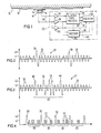
- FIG. 1 there is shown an elongate scale 10 attached to a substrate 12, which may for example be part of the fixed structure of a machine tool or co-ordinate measuring machine.
- a read head 14 is slidably moveable along the scale.
- the read head 14 may be fixed and the scale 10 may be moveable longitudinally relative to the read head.
- the scale 10 has recorded upon it a series of regular periodic marks, described more fully below.
- the read head 14 includes two sensors 16, spaced apart longitudinally by a distance of (n + 1/4) wavelengths of the pitch of the marks recorded on the scale 10. Accordingly, the sensors 16 give outputs on respective lines 18 which are in quadrature with each other.
- the marks on the scale 10 may be recorded by any technology for which appropriate sensors 16 can be devised. Our current preference is to provide a scale 10 in a magnetic medium, on which marks are recorded magnetically, with magnetic sensors 16, because this technology affords the easiest method of recording and reading the marks as described below.
- the sensors 16 may be magnetoresistive.
- the scales may be optical scales, having a layer of a material which is writeable optically, e.g. by photolithographic techniques. The material may have marks written to it by a light emitting diode, or for greater precision by a laser (e.g. a solid state laser). Photo sensors for reading an optical scale are readily available.
- a graph of the signal 20 recorded on the scale 10 to provide the marks comprises a sinusoidal signal of constant frequency and generally constant amplitude. For the most part, the amplitude is at a level L1, with occasional peaks 35 at a higher level L2 as described below.
- the period of the signal 20 constitutes the pitch of the marks on the scale, and may for example be one micron.
- the peaks 34, 35 of the signal constitute the marks.
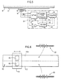
- a signal processor 22 has two limiters 24, 25, one for each line 18. The limiters 24, 25 switch at the zero-crossing points of the input signals and provide square wave outputs in quadrature to a quadrature processing circuit 26 of any conventional design.
- This may provide a pulse output to a counter 28, one pulse for each edge of the incoming quadrature square waves, and by detecting the relative phases of the incoming signals the quadrature processing circuit 26 may divide these pulses onto an up count line 30 when the read head is travelling in one direction, and a down count line 32 when it is travelling in the other direction, so that the counter 28 is incremented or decremented depending on the direction of travel.
- the counter 28 always indicates the relative position along the scale of the read head 14, in terms of the number of peaks of the signal 20 which have passed.
- one peak 34 of the signal has a much larger amplitude L2 than the ordinary peaks 35.
- This is detected by a threshold detector 36 connected to one of the lines 18, which detector has a threshold value lying between L1 and L2.
- This provides a pulse input 38 to the counter 28, causing the counter 28 to update its count by rounding it up or down to the nearest 1,000 counts.
- the high level peak 34 acts on the limiters 24, 25 in exactly the same way as the lower level peaks 35. Accordingly, this peak 34 has no adverse effect on the quadrature processing circuit 26, because the square waves rise and fall on the zero crossing points of the respective inputs on lines 18, thus eliminating both the different amplitudes of the peaks 34, 35 and any adverse phasing effects due to the different amplitudes. Both the peaks 34 and the peaks 35 act as incremental scale marks to increment or decrement the counter, and the occurrence of the high level peak 34 acts as a very simple code to indicate each thousandth mark.
- the peaks 34 may be more or less frequent. For example, they could occur every hundred marks, with the counter 28 being rounded to the nearest 0.1 mm when each peak 34 is detected.
- Fig. 2 shows an alternative recorded signal 21 which does give absolute position information to the counter 28.
- the signal is made up mainly of constant amplitude, constant frequency sinusoidal waves having peaks 35 at the level L1.
- a group 40 of peaks Periodically, however, (e.g. every 1 mm) there is provided a group 40 of peaks, some at least of which are at the higher level L2.
- the first and last peaks 42, 44 of the group 40 are at the higher level.
- the group 40 of peaks forms a binary word on which is encoded absolute position information.
- the peaks 42 and 44 form a start bit and a stop bit, and the illustration in Fig. 3 shows 8 bits of binary information in between the two.
- a low level peak represents a binary 0 while a high level peak represents a binary 1.
- a decoding circuit 46 In place of the direct connection 38 from the threshold detector 36 to the counter 28, there is provided a decoding circuit 46.
- the basic function of this circuit is to decode the serial information of the binary word 40 and provide a parallel output on a bus 48, which when it appears resets the counter 28 to the decoded value produced by the decoder 46.
- the decoder 46 receives the output of the high level detector 36, and also the low level detector 25, and gates them together to determine the presence of a binary 1 or a binary 0.
- the decoder 46 also has to cope with the fact that the read head 14 may be travelling in either direction, so that the bits of the binary word 40 may be received in either direction (i.e. starting with either the peak 42 or the peak 44).
- the decoder 46 also receives an input from the quadrature processing circuit 26, indicating direction of travel, or it may determine this from an appropriate arrangement of start and/or stop bits.
- the decoder 46 is also capable of detecting and ignoring invalid inputs, such as if the read head stops or reverses part way through reading a word 40.
- the design of such decoders is known, for example in the field of bar code readers.
- the information coded into the binary word 40 may, for example, be absolute position information, such as the position in millimetres (from an origin of the scale) of a scale mark which is associated with the binary word, e.g. the scale mark 42 or 44. This is fed directly into the counter 28 along the bus 48, to update the counter.
- Fig. 4 illustrates an example in which the scale is provided with periodic first marks 50 which are incremental scale marks to be counted, and these may for example appear at intervals of 50 microns.
- a signal processing circuit will usually be provided which includes a circuit for interpolating between the marks 50.
- the marks 50 are at the higher level L2.
- a series of second marks 52 at a lower level L1, comprising a binary word 80 similar to the binary word 40, containing information relating to an adjacent mark 50.
- the binary information as either the presence or absence of a low level peak 50.
- the high level peaks 50 can act as the start and stop bits for the binary word.
- information may be provided in respect of each one of the marks 50, or only in respect of some of them.
- each binary word 40 or 80 may simply contain linear error information for the associated mark 42, 44 or 50, e.g. ⁇ x in the case where the scale 10 has marks extending in a direction x.
- the decoder 46 provides an error output to an external computer, which adds the error ⁇ x to the output of the counter 28, giving the distance x from the origin.
- a practical coordinate measuring machine or machine tool normally has three orthogonally arranged scales 10 and read heads 14, for measuring movements on x, y and z axes. Because of deformations of various parts of the structure in operation of the machine, it is desirable to be able to take account of errors in three dimensions, caused by roll, pitch and yaw, which errors will differ over the entire volume of the machine. Thus, for example, the error ⁇ x for a given value of x will vary depending on the current values of y and z.
- each mark 42, 44 or 50 on the x scale 28 it would be possible if desired for there to be recorded in respect of each mark 42, 44 or 50 on the x scale 28 not merely one value of ⁇ x, but a table of such values ⁇ x for each value of y and z within the corresponding x plane.
- a table of values ⁇ x for each of the marks 42, 44 or 50 on the y scale it would be possible to record a table of values of ⁇ y, and for each of the marks 42, 44, 50 on the z scale it would be possible to produce a table of values ⁇ z.
- a first mark 42, 44, 50 at a position x0 has a corresponding binary word recording error information ⁇ x(y0, z0), relating to the error in the x value at position x0, y0, z0
- the next binary word 40, 80 along the x scale at a position x1 may record the error ⁇ x(y0, z1) at the position x1, the next may record the error ⁇ x(y0, z2) and so forth.
- the process would be repeated for a set of values of z at a position y1 (e.g.
- the next binary word 40, 80 along the x scale would record another value of ⁇ x(y0, z0) for the current x position.
- Errors ⁇ y and ⁇ z are recorded on the y and z scales in a similar manner.
- the computer is given a map of errors over the entire volume of the machine and can obtain intermediate values by interpolation.
- the quadrature processing circuit 26 now includes interpolation circuitry, and since such circuitry depends on the ratio of the instantaneous levels of the incoming sine waves on lines 18, the limiters 24, 25 are not included in these lines. Instead, the decoder 46 (if provided) has a low threshold level detector 56 on one input (and the high level threshold level detector 36 on the other) in order that it can function as before.
- interpolation circuitry makes use of the instantaneous ratio of sine waves, it could be confused if one input was in respect of a high peak 34 while the other was in respect of a low peak 35. To prevent this, three or more sensors 16 are spaced apart at intervals of (n + 1/4) wavelengths of the scale pitch.
- a "voting" circuit 54 receives the output of each sensor and is responsible for selecting two of them which are not located at a high peak 34 and passing them on to the processing circuit 26. If recorded signals of the type shown in Fig.
- voting circuit will need inputs from more than three sensors 16 (to ensure it is able to select two which are located at peaks of the same level); or alternatively the three sensors 16 should be at such a relatively large spacing from each other that only one of them ever coincides with a binary word 40 at once. Whilst such "voting" arrangements are known, their use in respect of scales is believed to be novel and inventive in itself.
- Fig. 6 shows an arrangement in which interpolation can be carried out without the need for a voting circuit 54.
- a scale 110 is divided into two parallel tracks 110A, 110B, on which are recorded respective signals 120 (which may be of the form shown in either Fig. 2 or Fig. 3).
- the read head 114 has two parallel sensors 116, one for each track.
- the two signals 120 are identical, but are recorded a quarter wavelength out of phase from each other. This phase difference is relative to the repective sensors 116, i.e. if the sensors are a quarter wavelength out of phase from each other than the signals are in phase.
- the signals from the two sensors 116 are taken directly to the interpolating quadrature processing circuit 26 in Fig. 5. Since the signals are identical in all but phase, the interpolation can depend on their instantaneous ratios in the conventional manner.
- the signal recorded on the scale could be in the form of square waves of the respective high and low amplitudes, instead of sine waves.
- a comparator may then be provided to compare the heights of successive recorded square waves (e.g. from suitably spaced sensors) in order to decide whether a given peak is a "high” or "low” peak. Such comparison is useful if the absolute values of L1 and L2 are not reliably known, e.g. if the signal intensity depends on the spacing between the scale and the read head.
Landscapes
- Physics & Mathematics (AREA)
- General Physics & Mathematics (AREA)
- Nonlinear Science (AREA)
- Transmission And Conversion Of Sensor Element Output (AREA)
Claims (12)
Applications Claiming Priority (6)
| Application Number | Priority Date | Filing Date | Title |
|---|---|---|---|
| GB8704204 | 1987-02-24 | ||
| GB878704204A GB8704204D0 (en) | 1987-02-24 | 1987-02-24 | Scales |
| GB878705304A GB8705304D0 (en) | 1987-03-06 | 1987-03-06 | Position determination apparatus |
| GB8705304 | 1987-03-06 | ||
| GB8706789 | 1987-03-21 | ||
| GB878706789A GB8706789D0 (en) | 1987-03-21 | 1987-03-21 | Scales |
Publications (2)
| Publication Number | Publication Date |
|---|---|
| EP0303676A1 EP0303676A1 (de) | 1989-02-22 |
| EP0303676B1 true EP0303676B1 (de) | 1991-03-20 |
Family
ID=27263323
Family Applications (1)
| Application Number | Title | Priority Date | Filing Date |
|---|---|---|---|
| EP88902508A Expired EP0303676B1 (de) | 1987-02-24 | 1988-02-24 | Teilung für wegmessapparat |
Country Status (4)
| Country | Link |
|---|---|
| US (1) | US5004982A (de) |
| EP (1) | EP0303676B1 (de) |
| JP (1) | JPH01502452A (de) |
| WO (1) | WO1988006717A1 (de) |
Cited By (1)
| Publication number | Priority date | Publication date | Assignee | Title |
|---|---|---|---|---|
| DE19802064B4 (de) * | 1998-01-21 | 2007-05-24 | Windhorst Beteiligungsgesellschaft Mbh | Sensormagnet, insbesondere zur Positionserfassung in Kombination mit einem Sensorelement, und Magnetisierspule für dessen Magnetisierung |
Families Citing this family (20)
| Publication number | Priority date | Publication date | Assignee | Title |
|---|---|---|---|---|
| GB8909788D0 (en) * | 1989-04-28 | 1989-06-14 | Renishaw Plc | Optical metrological scale |
| US5461311A (en) * | 1992-12-24 | 1995-10-24 | Kayaba Kogyo Kabushiki Kaisha | Rod axial position detector including plural scales wherein nonmagnetized portions have differing spacing and differing depths and means for calculating the absolute position are provided |
| AT407196B (de) * | 1993-11-17 | 2001-01-25 | Amo Automatisierung Messtechni | Positionsmelder für automatisierung |
| EP0668486A3 (de) * | 1994-02-22 | 1997-07-30 | Heidenhain Gmbh Dr Johannes | Längen- oder Winkelmesseinrichtung. |
| DE19518664C2 (de) * | 1995-05-20 | 2003-02-13 | Christian Rathjen | Verfahren zur Bestimmung der Position zweier zueinander bewegbarer Körper |
| US5929789A (en) * | 1997-04-09 | 1999-07-27 | Hewlett-Packrd Company | Single channel incremental position encorder with incorporated reference mark |
| GB9926574D0 (en) * | 1999-11-11 | 2000-01-12 | Renishaw Plc | Absolute position measurement |
| DE10041507A1 (de) * | 2000-08-11 | 2002-02-28 | Takata Petri Ag | Lenkwinkelsensor für Kraftfahrzeuge |
| US20020190710A1 (en) * | 2001-02-13 | 2002-12-19 | Asm Automation Sensorik Messtechnik Gmbh | Magnetic length measuring device |
| DE10123539B4 (de) * | 2001-05-15 | 2008-07-17 | Asm Automation Sensorik Messtechnik Gmbh | Magnetische Längenmessvorrichtung |
| US20040262502A1 (en) | 2003-06-26 | 2004-12-30 | Xerox Corporation | Position encoder |
| DE102005031333A1 (de) * | 2005-07-05 | 2007-01-11 | Zf Friedrichshafen Ag | Positionsdetektion an einer Stange |
| WO2010086585A1 (en) * | 2009-01-27 | 2010-08-05 | Renishaw Plc | Magnetic encoder apparatus |
| JP5077717B2 (ja) * | 2010-04-12 | 2012-11-21 | 村田機械株式会社 | 磁極検出システム |
| DE102011078717A1 (de) * | 2011-07-06 | 2013-01-10 | Continental Teves Ag & Co. Ohg | Einrichtung zur Messung von Winkel und Winkelgeschwindigkeit oder Weg und Geschwindigkeit |
| GB201204066D0 (en) | 2012-03-08 | 2012-04-18 | Renishaw Plc | Magnetic encoder apparatus |
| RU2518977C1 (ru) * | 2012-12-17 | 2014-06-10 | Сергей Владимирович Карпенко | Адаптивный датчик идентификации и контроля положения нагретых неметаллических и ненагретых неметаллических изделий |
| JP5717787B2 (ja) * | 2013-05-09 | 2015-05-13 | Thk株式会社 | リニアエンコーダ装置、及び基準位置検出方法 |
| DE102015121812B4 (de) * | 2015-12-15 | 2017-11-02 | Bogen Electronic Gmbh | Gegenstand, Verfahren zum Herstellen des Gegenstands und Verfahren zum Bestimmen einer Position des Gegenstands |
| JP6234497B2 (ja) * | 2016-03-15 | 2017-11-22 | Thk株式会社 | エンコーダ装置及びエンコーダ装置付き運動案内装置 |
Family Cites Families (11)
| Publication number | Priority date | Publication date | Assignee | Title |
|---|---|---|---|---|
| GB212644A (de) * | ||||
| US2947168A (en) * | 1954-06-23 | 1960-08-02 | Denis C Yang | Power indicator |
| JPS5725766B2 (de) * | 1973-12-12 | 1982-06-01 | ||
| JPS54163061A (en) * | 1978-06-15 | 1979-12-25 | Nippon Denso Co | Revolution positional detector |
| DE3144334C2 (de) * | 1981-11-07 | 1985-06-13 | Dr. Johannes Heidenhain Gmbh, 8225 Traunreut | Wegmeßeinrichtung mit Referenzmarken |
| DE3201005A1 (de) * | 1982-01-15 | 1983-07-28 | Dr. Johannes Heidenhain Gmbh, 8225 Traunreut | Einrichtung zur fehlerkorrektur bei positionsmesssystemen |
| JPS58148914A (ja) * | 1982-03-02 | 1983-09-05 | Fanuc Ltd | パルスコ−ダ |
| GB2126444B (en) * | 1982-09-01 | 1986-03-19 | Rosemount Eng Co Ltd | Position measuring apparatus |
| DD219566A1 (de) * | 1983-08-05 | 1985-03-06 | Harry Trumpold | Hochaufloesendes optisches laengenmessverfahren mit codiertem absolutmassstab zur durchfuehrung des verfahrens |
| US4628298A (en) * | 1984-06-22 | 1986-12-09 | Bei Motion Systems Company, Inc. | Chain code encoder |
| CA1306618C (en) * | 1987-03-25 | 1992-08-25 | Normand Guay | Torquemeter |
-
1988
- 1988-02-24 EP EP88902508A patent/EP0303676B1/de not_active Expired
- 1988-02-24 WO PCT/GB1988/000119 patent/WO1988006717A1/en not_active Application Discontinuation
- 1988-02-24 JP JP63502331A patent/JPH01502452A/ja active Pending
-
1990
- 1990-07-23 US US07/555,792 patent/US5004982A/en not_active Expired - Fee Related
Cited By (1)
| Publication number | Priority date | Publication date | Assignee | Title |
|---|---|---|---|---|
| DE19802064B4 (de) * | 1998-01-21 | 2007-05-24 | Windhorst Beteiligungsgesellschaft Mbh | Sensormagnet, insbesondere zur Positionserfassung in Kombination mit einem Sensorelement, und Magnetisierspule für dessen Magnetisierung |
Also Published As
| Publication number | Publication date |
|---|---|
| WO1988006717A1 (en) | 1988-09-07 |
| EP0303676A1 (de) | 1989-02-22 |
| US5004982A (en) | 1991-04-02 |
| JPH01502452A (ja) | 1989-08-24 |
Similar Documents
| Publication | Publication Date | Title |
|---|---|---|
| EP0303676B1 (de) | Teilung für wegmessapparat | |
| US4701615A (en) | Measuring scale coding system for length or angle measuring instruments | |
| EP0013799B1 (de) | Kodierer für Längen- oder Winkelmessvorrichtungen mit hoher Genauigkeit | |
| US4519140A (en) | System for identifying reference marks in a path measuring device | |
| US4794251A (en) | Apparatus for measuring lengths or angles | |
| JP4008356B2 (ja) | アブソリュート位置測定法 | |
| EP0501453B1 (de) | Kombinierter optischer und kapazitiver Apparat zur Messung der absoluten Position | |
| US5235181A (en) | Absolute position detector for an apparatus for measuring linear angular values | |
| EP2438402B1 (de) | Positionsmesseinrichtung und zugehöriges betriebsverfahren | |
| US7461464B2 (en) | Position measuring arrangement | |
| EP1466142B1 (de) | Enkoder mit referenzmarkierungen | |
| CA1281182C (en) | Displacement measuring apparatus | |
| US20070256313A1 (en) | Scale Reading Apparatus | |
| US4606642A (en) | Measuring arrangement for the clear scanning of at least one reference mark allocated to a graduation | |
| US4462159A (en) | Reference mark selection system for measuring apparatus | |
| US6031224A (en) | Position measuring system | |
| Petriu et al. | On the position measurement of automated guided vehicles using pseudorandom encoding | |
| US3891143A (en) | Encoding apparatus having an improved code permitting error reading and error detection | |
| JP3442869B2 (ja) | 光学式アブソリュートエンコーダ | |
| US6898865B2 (en) | Measuring system for recording absolute angular or position values | |
| KR19990078331A (ko) | 광학식리니어스케일원점신호발생장치 | |
| US7359826B2 (en) | Method and device for detection of oscillations by a position measuring system | |
| KR101341804B1 (ko) | 절대 위치 측정 방법, 절대 위치 측정 장치, 및 스케일 | |
| JP2697159B2 (ja) | 絶対位置検出装置 | |
| JP2678386B2 (ja) | 位置検出装置 |
Legal Events
| Date | Code | Title | Description |
|---|---|---|---|
| PUAI | Public reference made under article 153(3) epc to a published international application that has entered the european phase |
Free format text: ORIGINAL CODE: 0009012 |
|
| 17P | Request for examination filed |
Effective date: 19881022 |
|
| AK | Designated contracting states |
Kind code of ref document: A1 Designated state(s): CH DE FR GB IT LI SE |
|
| 17Q | First examination report despatched |
Effective date: 19900201 |
|
| GRAA | (expected) grant |
Free format text: ORIGINAL CODE: 0009210 |
|
| RAP3 | Party data changed (applicant data changed or rights of an application transferred) |
Owner name: RENISHAW PLC |
|
| AK | Designated contracting states |
Kind code of ref document: B1 Designated state(s): CH DE FR GB IT LI SE |
|
| ITF | It: translation for a ep patent filed |
Owner name: BARZANO' E ZANARDO MILANO S.P.A. |
|
| REF | Corresponds to: |
Ref document number: 3862082 Country of ref document: DE Date of ref document: 19910425 |
|
| ET | Fr: translation filed | ||
| PLBI | Opposition filed |
Free format text: ORIGINAL CODE: 0009260 |
|
| PGFP | Annual fee paid to national office [announced via postgrant information from national office to epo] |
Ref country code: FR Payment date: 19920110 Year of fee payment: 5 |
|
| PGFP | Annual fee paid to national office [announced via postgrant information from national office to epo] |
Ref country code: GB Payment date: 19920115 Year of fee payment: 5 |
|
| PGFP | Annual fee paid to national office [announced via postgrant information from national office to epo] |
Ref country code: SE Payment date: 19920120 Year of fee payment: 5 |
|
| PGFP | Annual fee paid to national office [announced via postgrant information from national office to epo] |
Ref country code: CH Payment date: 19920121 Year of fee payment: 5 |
|
| 26 | Opposition filed |
Opponent name: DR. JOHANNES HEIDENHAIN GMBH Effective date: 19911218 |
|
| PGFP | Annual fee paid to national office [announced via postgrant information from national office to epo] |
Ref country code: DE Payment date: 19930125 Year of fee payment: 6 |
|
| PG25 | Lapsed in a contracting state [announced via postgrant information from national office to epo] |
Ref country code: GB Effective date: 19930224 |
|
| PG25 | Lapsed in a contracting state [announced via postgrant information from national office to epo] |
Ref country code: SE Effective date: 19930225 |
|
| PG25 | Lapsed in a contracting state [announced via postgrant information from national office to epo] |
Ref country code: LI Free format text: LAPSE BECAUSE OF NON-PAYMENT OF DUE FEES Effective date: 19930228 Ref country code: CH Free format text: LAPSE BECAUSE OF NON-PAYMENT OF DUE FEES Effective date: 19930228 |
|
| GBPC | Gb: european patent ceased through non-payment of renewal fee |
Effective date: 19930224 |
|
| PG25 | Lapsed in a contracting state [announced via postgrant information from national office to epo] |
Ref country code: FR Effective date: 19931029 |
|
| REG | Reference to a national code |
Ref country code: CH Ref legal event code: PL |
|
| REG | Reference to a national code |
Ref country code: FR Ref legal event code: ST |
|
| RDAG | Patent revoked |
Free format text: ORIGINAL CODE: 0009271 |
|
| STAA | Information on the status of an ep patent application or granted ep patent |
Free format text: STATUS: PATENT REVOKED |
|
| 27W | Patent revoked |
Effective date: 19931218 |
|
| EUG | Se: european patent has lapsed |
Ref document number: 88902508.6 Effective date: 19930912 |