EP0302998A2 - Werkzeugrevolver für Werkzeugmaschinen - Google Patents
Werkzeugrevolver für Werkzeugmaschinen Download PDFInfo
- Publication number
- EP0302998A2 EP0302998A2 EP88106128A EP88106128A EP0302998A2 EP 0302998 A2 EP0302998 A2 EP 0302998A2 EP 88106128 A EP88106128 A EP 88106128A EP 88106128 A EP88106128 A EP 88106128A EP 0302998 A2 EP0302998 A2 EP 0302998A2
- Authority
- EP
- European Patent Office
- Prior art keywords
- tool
- turret
- sleeve
- axis
- rotation
- Prior art date
- Legal status (The legal status is an assumption and is not a legal conclusion. Google has not performed a legal analysis and makes no representation as to the accuracy of the status listed.)
- Granted
Links
- 230000008878 coupling Effects 0.000 claims abstract description 17
- 238000010168 coupling process Methods 0.000 claims abstract description 17
- 238000005859 coupling reaction Methods 0.000 claims abstract description 17
- 238000006073 displacement reaction Methods 0.000 claims description 6
- 230000000694 effects Effects 0.000 claims description 5
- 230000003993 interaction Effects 0.000 claims 1
- 230000002093 peripheral effect Effects 0.000 abstract description 2
- 238000003754 machining Methods 0.000 description 7
- 230000009471 action Effects 0.000 description 3
- 230000004913 activation Effects 0.000 description 1
- 230000004323 axial length Effects 0.000 description 1
- 230000008901 benefit Effects 0.000 description 1
- 238000010276 construction Methods 0.000 description 1
- 230000007812 deficiency Effects 0.000 description 1
- 230000005284 excitation Effects 0.000 description 1
- 238000000034 method Methods 0.000 description 1
- 230000008569 process Effects 0.000 description 1
- 238000005096 rolling process Methods 0.000 description 1
- 238000007789 sealing Methods 0.000 description 1
- 238000000926 separation method Methods 0.000 description 1
- 125000006850 spacer group Chemical group 0.000 description 1
Images


Classifications
-
- B—PERFORMING OPERATIONS; TRANSPORTING
- B23—MACHINE TOOLS; METAL-WORKING NOT OTHERWISE PROVIDED FOR
- B23Q—DETAILS, COMPONENTS, OR ACCESSORIES FOR MACHINE TOOLS, e.g. ARRANGEMENTS FOR COPYING OR CONTROLLING; MACHINE TOOLS IN GENERAL CHARACTERISED BY THE CONSTRUCTION OF PARTICULAR DETAILS OR COMPONENTS; COMBINATIONS OR ASSOCIATIONS OF METAL-WORKING MACHINES, NOT DIRECTED TO A PARTICULAR RESULT
- B23Q5/00—Driving or feeding mechanisms; Control arrangements therefor
- B23Q5/02—Driving main working members
- B23Q5/04—Driving main working members rotary shafts, e.g. working-spindles
-
- B—PERFORMING OPERATIONS; TRANSPORTING
- B23—MACHINE TOOLS; METAL-WORKING NOT OTHERWISE PROVIDED FOR
- B23B—TURNING; BORING
- B23B29/00—Holders for non-rotary cutting tools; Boring bars or boring heads; Accessories for tool holders
- B23B29/24—Tool holders for a plurality of cutting tools, e.g. turrets
- B23B29/32—Turrets adjustable by power drive, i.e. turret heads
- B23B29/323—Turrets with power operated angular positioning devices
-
- B—PERFORMING OPERATIONS; TRANSPORTING
- B23—MACHINE TOOLS; METAL-WORKING NOT OTHERWISE PROVIDED FOR
- B23Q—DETAILS, COMPONENTS, OR ACCESSORIES FOR MACHINE TOOLS, e.g. ARRANGEMENTS FOR COPYING OR CONTROLLING; MACHINE TOOLS IN GENERAL CHARACTERISED BY THE CONSTRUCTION OF PARTICULAR DETAILS OR COMPONENTS; COMBINATIONS OR ASSOCIATIONS OF METAL-WORKING MACHINES, NOT DIRECTED TO A PARTICULAR RESULT
- B23Q39/00—Metal-working machines incorporating a plurality of sub-assemblies, each capable of performing a metal-working operation
- B23Q39/02—Metal-working machines incorporating a plurality of sub-assemblies, each capable of performing a metal-working operation the sub-assemblies being capable of being brought to act at a single operating station
-
- B—PERFORMING OPERATIONS; TRANSPORTING
- B23—MACHINE TOOLS; METAL-WORKING NOT OTHERWISE PROVIDED FOR
- B23Q—DETAILS, COMPONENTS, OR ACCESSORIES FOR MACHINE TOOLS, e.g. ARRANGEMENTS FOR COPYING OR CONTROLLING; MACHINE TOOLS IN GENERAL CHARACTERISED BY THE CONSTRUCTION OF PARTICULAR DETAILS OR COMPONENTS; COMBINATIONS OR ASSOCIATIONS OF METAL-WORKING MACHINES, NOT DIRECTED TO A PARTICULAR RESULT
- B23Q2220/00—Machine tool components
- B23Q2220/002—Tool turrets
Definitions
- the invention relates to a tool turret for machine tools, in particular lathes or NC machining units, with a turret head which defines a turret axis and forms a rotary bearing for a tool disk which can be rotated about the turret axis and which can be indexed in rotating steps and, according to a number of tool stations, along it Has circumferentially distributed tool receptacles, in each of which tool holders provided with a holding shank can be received, of which the rotating tools provided have a drive shaft coaxial with the holding shank and rotatably mounted axially parallel to the turret axis, which can be driven by means of a drive device which can be rotated coaxially with the turret axis has mounted toothed ring with external spur toothing, which can be driven by a toothed pinion meshing with it and driven by a motor.
- a tool turret of this type is already known, cf. DE-PS 32 02 042. If there are several tool holders with rotary tools in the tool holders of the tool disk of the known turret, then the known solution all rotary tools driven in operation at the operating speed and not only the rotary tool that is located in the station, which is effective as a work station for the respective machining process.
- the idle running of the other rotary tools that are not in the work station in question means unnecessary wear of the associated bearing and gear devices and unnecessary loss of drive power.
- the running of rotary tools that are not involved in the machining process and are located outside the work station constitutes a significant safety deficiency.
- the invention is based on the object of designing a tool turret of the type mentioned in such a way that a desired rotary tool can be individually driven by a plurality of tool holders located in the tool holders of the tool disk with rotary tools.
- this object is achieved according to the invention in that the toothed ring is mounted in the turret head and is in drive connection with a sliding wheel which can be rotated in the turret head about an axis of rotation parallel to the turret axis, the position of which is selected such that the receiving shaft is one the desired tool holder can be aligned to the axis of rotation by means of a turning step of the tool disk, so that the sliding wheel can be displaced axially along its axis of rotation between a coupling position advanced against the tool disk, in which the drive shaft of the tool shaft and the sliding wheel are in clutch engagement with each other, and a retracted uncoupling position , and that a control device is provided for selectively moving the sliding wheel between the coupling position and the uncoupling position.
- the arrangement of the toothed ring in the turret itself ie the spatial separation of the toothed ring from the tool disc, it contains no gear element that is continuously driven during operation.
- the control device can be designed in such a way that the sliding wheel is automatically retracted into the uncoupling position by one turning step, depending on the process of advancing the tool disc, and is automatically pushed back into the coupling position at the end of a turning step.
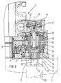
- FIG. 1 shows a front view of a turret 1 of a tool turret for use in a lathe or an NC machining unit in the form of a generally cylindrical housing which can be attached, for example, to a cross support of a lathe in question or a stand or slide of a machining unit .
- the turret 1 has a circular front flat surface 3, on which a tool disk, not shown in FIG. 1, which is only indicated in FIG. 2 and is designated by 5, can be rotatably attached in the usual manner, the tool disk 5 being supported by a centering pin 7 is centered, which protrudes somewhat from the flat surface 3 and defines a central turret axis 8.
- the tool disk 5 is in a known manner on the turret 1 switchable in rotation steps, the number and angle of rotation are selected according to the number and position of tool stations of the tool disk 5.
- the tool stations of the tool disk 5 are tool receptacles 11 (see FIG. 2), in which tool holders with their receptacle shaft 12 can be received in such a way that the longitudinal axis of the receptacle shaft 12 in question runs axially parallel to the turret axis 8.
- the holding shank 12 shown in FIG. 2 belongs to a tool holder which is equipped with a rotary tool. This can be driven by means of a drive shaft 13 which is coaxially rotatably mounted in the receiving shaft 12, the end section 15 of which is freely accessible in the end region 17 of the tool holder 11 which faces the flat surface 3, so that the end section 15 of the drive shaft 13 in a manner to be described below with a rotary drive device is connectable.
- This drive device has, as can be seen from Fig. 1, a laterally attached to the turret 1 gear motor 19, the driven gear 20 (Fig. 1) meshes with the outer end teeth of a toothed ring 21 which is in the turret 1 at a short distance from the front Flat surface 3 is rotatably mounted about the turret axis 8.
- a toothed pinion 23 meshing with the toothed ring 21 and driven by the latter is rotatably and axially immovable in the shown embodiment in the turret head 1 at a point approximately diametrically opposite the wheel 20 in such a way that its axis of rotation 25 runs axially parallel to the turret axis 8 and to the turret axis 8 has the same radial distance as the longitudinal axes of the tool holders 11 of the tool disk 5.
- the pinion 23 has on both sides next to his
- the sliding wheel In order to transmit the rotational movement of the pinion 23, which is continuously driven during operation via the toothed ring 21, to the end section 15 of the drive shaft 13 of a tool in a tool holder 11 aligned with the axis of rotation 25, there is a sliding wheel which can be moved along the axis of rotation 25 and which can be moved with the Pinion 23 is connected to rotation.
- the sliding wheel is designed in the form of a circular cylindrical sleeve 31, the outside of which is provided with straight spline teeth 33.
- the sleeve 31 is axially displaceably mounted in the hub bore of the pinion 23, the outer spline 33 being guided in the sleeve 31 in splines 35 of the hub bore of the pinion 23, so that the sleeve 31 and pinion 23 are positively connected to rotate.
- the sleeve 31 In its front end section facing the flat surface 3, the sleeve 31 has keyways 37 on its inner wall.
- an external spline 39 on the end section 15 of the drive shaft 13 of a rotary tool arranged in the tool holder 11 comes into coupling engagement with the splines 37 in the sleeve 31.
- a control device For the optional displacement of the Sleeve 31 between the retracted decoupling position shown in FIG. 2 and the advanced coupling position in which the Spline grooves 37 of the sleeve 31 with the spline 39 on the end portion 15 of the drive shaft 13 are engaged, a control device is provided.
- this control device has an actuator designated 41 as a whole in FIG. 1, which is arranged on the outside of the turret head 1, approximately opposite the geared motor 19.
- the actuator 41 has a hydraulically actuated working cylinder 42, by means of which a shift lever 43 can be pivoted about a pivot pin 44.
- the shift lever 43 of which only the forked end 45 can be seen in FIG. 2, which serves as a shift fork, cooperates with lateral pins 47 of a control pin 49 projecting into the bore of the sleeve 31.
- the control pin 49 extends coaxially to the axis of rotation 25, but is not rotatable about the axis 25 because of the engagement between its lateral pins 47 and the ends 45 of the shift lever 43 serving as a shift fork.
- the sleeve 31 has an enlarged bore section 51 in the connection to the bore section having the keyways 37, in which two roller bearings 53 are arranged on the control mandrel 49.
- cup-shaped driver body 54 which, in cooperation with the outer ring of the associated roller bearing 53 and the inner shoulder of the sleeve 31, axially displaces the control mandrel 49 in the direction can take the tool disk 5 with it and shift it into the coupling position.
- a spacer sleeve 55 is inserted between the two roller bearings 53.
- the outer ring of the roller bearing 53 adjacent to the lateral pin 47 is in the axial direction by a retaining ring 57 fixed.
- a displacement movement of the control mandrel 49 in FIG. 2 is transmitted to the right on the sleeve 31 in order to move it into the end coupling position shown in FIG. 2.
- the actuator 41 of the control device which moves the switching lever 43 could have a different power drive instead of a hydraulic working cylinder 42, for example a control magnet or a pneumatic drive.
- the geared motor 19 with the wheel 20 driving the toothed ring 21 is arranged on one side next to the turret 1 and the toothed pinion 23, which is driven by the toothed ring 21, is located in the diametrically opposite one to the wheel 20 Side area of the turret head 1.
- the positions of the drive motor (gear motor 19) and the driven pinion 23, the axis 25 of which determines the working position of the rotary tool to be driven can be freely selected.
- the motor on the top of the turret 1 and the pinion 23 defining the working position could be arranged on the underside of the turret 1. It is also possible to provide more than one working position, for example by arranging the motor on the top or bottom of the turret 1 and by providing a pinion 23 with associated switching and control devices on each side of the motor.
- FIG. 3 which serves to explain a second exemplary embodiment of a tool turret, parts that correspond to those of the first described exemplary embodiment are denoted by reference numerals enlarged by 100 in comparison.
- This second exemplary embodiment differs from the first described exemplary embodiment mainly in that the control device for the axial displacement movements of the sleeve 131 has a different construction along the axis of rotation 125.
- the sleeve 131 is normally separated by a release spring 161 in the position shown in FIG. 3 shown uncoupled.
- the release spring 161 is supported on the one hand on the inner end of a control drum 162 and presses with its other end on a slide 163 which is displaceable on a shaft 164 which is concentric with the axis of rotation 125.
- the slider 163 has a circumferential groove 165, in which a control pin 166 engages in the wall of the sleeve 131, a limiting shoulder of the circumferential groove 165 being held in contact with the control pin 166 by the force of the release spring 161.
- the force of the release spring 161 thus acts on the control pin 166 via the slider 163 and seeks to shift it to the right (viewing direction according to FIG. 3).
- the control drum 162 is also capable of absorbing axial forces
- Rolling bearing 167 is rotatably mounted about the axis of rotation 125, but axially immovable, and is frictionally coupled to the sleeve 131, which is connected to the pinion 123 for rotation via its external spline 133.
- a sealing ring 168 which is disposed between the enlarged inner bore portion 151 of the sleeve 131 and the peripheral portion therein of the control drum 162, forms a frictional engagement which normally rotates the control drum 162 with the sleeve 131.
- the control drum 162 interacts with a magnetic brake 170, which can be activated selectively via an excitation cable 171.
- the magnetic brake 170 is able to generate a braking torque that exceeds the drag effect of the frictional engagement between the sleeve 131 and the control drum 162.
- the control pin 166 When the magnetic brake 170 is not activated, ie when the control drum 162 can be freely rotated with the sleeve 131, the control pin 166 bears against the end of the recess 172 on the right in FIG. 3 under the action of the release spring 161. If the magnetic brake 170 is now activated, the control drum 162 remains behind with respect to the rotary movement of the sleeve 131, which causes the control pin 166 in the recess 172 designed as a spiral slot or screw slot to migrate to its end 173 on the left in the drawing. This movement of the control pin 166 results in a corresponding axial displacement movement of the sleeve 131 into the advanced coupling position. If the magnetic brake 170 is deactivated again, the control pin 166 in the recess 172 moves again under the action of the spring 161 into the end position shown in FIG. 3, the sleeve 131 being moved into the uncoupling position.
- a control drum 262 which is rotatably and axially immovably mounted with respect to the wire axis 225 by means of a roller bearing 267 and whose inner end 269 interacts with a magnetic brake 270.
- the control drum 262 also has a recess 272 in the form of a spiral or screw slot.
- the recess 272 is penetrated by a control pin 266, which is normally held in the end part of the recess 272 on the right in FIG. 4 by the force of a release spring 261.
- control pin 266 is not, however, mounted in the wall of the sleeve 231, but rather on the slider 263 slidably mounted on the shaft 264.
- the axial position of the slider 263 therefore depends on the position of the control pin 266 in the recess 272 onwards.
- Activation of the magnetic brake 270 causes the rotary movement of the control drum 262 to remain behind the sleeve 231 and the slider 263, which is connected to the sleeve 231 by means of a driving pin 277 for rotation, which is in a straight, engages axially parallel driving slot 278 of the sleeve 231.
- a driving pin 277 for rotation which is in a straight, engages axially parallel driving slot 278 of the sleeve 231.
- the driving pin 277 is located on the inner end 281 of the driving slot 278 on the right in the drawing and thereby blocks a displacement movement of the Sleeve 231 to the left in the advanced clutch position, although the sleeve 231 is biased by an engagement spring 283 for this movement in the clutch position.
- the engagement spring 283 is seated on the shaft 264 and is supported on the one hand on the slide 263 and on the other hand on the front closed end of the inner bore of the sleeve 231.
- the control pin 266 moves within the recess 272, the slide 263 being displaced to the left against the force of the release spring 261 in the drawing.
- the corresponding movement of the driving pin 277 to the left releases the sleeve 231, so that it can also move to the left into the coupling position under the action of the engagement spring 283, with outer driving lugs 287 of the sleeve 231 with associated driving members on the drive shaft of a corresponding rotary tool come into clutch engagement.
- the embodiment according to FIG. 4 is therefore the principle of a clutch for tool drives sprung by means of the engagement spring 283 in accordance with the VDMA guidelines.
Landscapes
- Engineering & Computer Science (AREA)
- Mechanical Engineering (AREA)
- Cutting Tools, Boring Holders, And Turrets (AREA)
- Automatic Tool Replacement In Machine Tools (AREA)
- Harvester Elements (AREA)
Abstract
- 1. Werkzeugrevolver für Werkzeugmaschinen.
- 2. Ein Werkzeugrevolver weist einen Revolverkopf (1) auf, an dem eine Werkzeugscheibe (5) um die Revolverachse drehbar gelagert ist. Die Werkzeugscheibe (5) weist längs ihres Umfangbereiches verteilt angeordnete Werkzeugaufnahmen (11) auf, von denen die für Rotationswerkzeuge vorgesehenen Aufnahmen (11) eine drehbar gelagerte Antreibswelle (13) enthalten. Mit der Antriebswelle (13) der in der Arbeitsposition befindlichen Werkzeugantrieb (11) ist ein im Revolverkopf (1) vorgesehener Werkzeugantrieb wahlweise kuppelbar, der ein im Revolverkopf (1) axial verschiebbar gelagertes Schieberad (31) aufweist, das mittels einer Steuereinrichtung wahlweise zwischen einer vorgeschobenen Kupplungsstellung, in der es mit der Antriebswelle (13) in Kupplungseingriff ist, und einer zurückgezogenen Entkuppelstellung verschiebbar ist.
Description
- Die Erfindung betrifft einen Werkzeugrevolver für Werkzeugmaschinen, insbesondere Drehmaschinen oder NC-Bearbeitungseinheiten, mit einem Revolverkopf, der eine Revolverachse definiert und eine Drehlagerung für eine um die Revolverachse drehbare Werkzeugscheibe bildet, die in Drehschritten weiterschaltbar ist und, einer Anzahl von Werkzeugstationen entsprechend, längs ihres Umfangsbereiches verteilt angeordnete Werkzeugaufnahmen aufweist, in denen jeweils mit einem Aufnahmeschaft versehene Werkzeughalter aufnehmbar sind, von denen die für Rotationswerkzeuge vorgesehenen je eine zum Aufnahmeschaft koaxiale, zur Revolverachse achsparallel drehbar gelagerte Antriebswelle aufweisen, die mittels einer Antriebseinrichtung antreibbar ist, die einen zur Revolverachse koaxial drehbar gelagerten Zahnring mit äußerer Stirnverzahnung aufweist, der durch ein mit ihm kämmendes, motorisch antreibbares Zahnritzel antreibbar ist.
- Ein Werkzeugrevolver dieser Art ist bereits bekannt, vgl. DE-PS 32 02 042. Wenn sich in den Werkzeugaufnahmen der Werkzeugscheibe des bekannten Revolvers mehrere Werkzeughalter mit Rotationswerkzeugen befinden, dann sind bei der bekannten Lösung sämtliche Rotationswerkzeuge im Betrieb mit der Betriebsdrehzahl angetrieben und nicht nur dasjenige Rotationswerkzeug, das sich in der Station befindet, welche für den jeweiligen Bearbeitungsvorgang als Arbeitsstation wirksam ist. Das Leerlaufen der übrigen, nicht in der betreffenden Arbeitsstation befindlichen Rotationswerkzeuge bedeutet einen unnötigen Verschleiß der zugehörigen Lager- und Getriebeeinrichtungen sowie unnötige Verluste an Antriebsleistung. Insbesondere stellt das Mitlaufen von am Bearbeitungsvorgang nicht beteiligten, außerhalb der Arbeitsstation befindlichen Rotationswerkzeugen einen wesentlichen Sicherheitsmangel dar.
- Der Erfindung liegt die Aufgabe zugrunde, einen Werkzeugrevolver der besagten Art so auszubilden, daß von einer Mehrzahl von in den Werkzeugaufnahmen der Werkzeugscheibe befindlichen Werkzeughaltern mit Rotationswerkzeugen eine gewünschtes Rotationswerkzeug einzeln antreibbar ist.
- Bei einem Werkzeugrevolver der eingangs genannten Art ist diese Aufgabe erfindungsgemäß dadurch gelöst, daß der Zahnring im Revolverkopf gelagert und mit einem Schieberad in Antriebsverbindung ist, das im Revolverkopf um eine zur Revolverachse parallele Drehachse drehbar ist, deren Lage so gewählt ist, daß der Aufnahmeschaft einer gewünschten Werkzeugaufnahme durch einen Drehschritt der Werkzeugscheibe auf die Drehachse ausrichtbar ist, daß das Schieberad längs seiner Drehachse axial zwischen einer gegen die Werkzeugscheibe vorgeschobenen Kupplungsstellung, in der die Antriebswelle des Werkzeugschaftes und das Schieberad je endseitig miteinander in Kupplungseingriff sind, und einer zurückgezogenen Entkuppelstellung verschiebbar ist, und daß eine Steuereinrichtung zum wahlweisen Verschieben des Schieberades zwischen Kupplungsstellung und Entkuppelstellung vorgesehen ist. Durch die Anordnung des Zahnringes im Revolverkopf selbst, d. h. die räumliche Trennung des Zahnringes von der Werkzeugscheibe, enthält diese kein im Betrieb dauernd angetriebenes Getriebeelement. Durch Vorschieben des mit dem Zahnring gekuppelten Schieberades mittels der Steuereinrichtung in die Kuppelstellung, in der das Schieberad mit der Antriebswelle desjenigen Werkzeughalters gekuppelt ist, der auf die Drehachse des Schieberads jeweils ausgerichtet ist, läßt sich wahlweise ein gewünschtes Rotationswerkzeug für einen betreffenden Bearbeitungsvorgang antreiben.
- Durch wahlweisen Antrieb nur eines einzigen gewünschten Rotationswerkzeugs ist nicht nur ein unnötiger Verschleiß der Lager- und Getriebeeinrichtungen der übrigen in der Werkzeugscheibe befindlichen Rotationswerkzeuge und der unnötige Leistungsverlust aufgrund des Leerlaufens der nicht benutzten Rotationswerkzeuge vermieden, sondern es ist auch den zu stellenden Sicherheitsanforderungen Genüge geleistet, weil während des Betriebes, d. h. während ein gewünschtes Rotationswerkzeug einen Bearbeitungsvorgang ausführt, die übrigen, außerhalb der Arbeitsstation befindlichen Rotationswerkzeuge im Stillstand sind und daher keine Gefährdung des Bedienpersonals verursachen können.
- Die Steuereinrichtung kann so ausgebildet sein, daß das Schieberad in Abhängigkeit vom Vorgang des Weiterschaltens der Werkzeugscheibe um einen Drehschritt selbsttätig in die Entkuppelstellung zurückgezogen und am Ende eines Drehschritts selbsttätig wieder in die Kupplungsstellung vorgeschoben wird.
- Nachstehend ist die Erfindung anhand von in der Zeichnung dargestellten Ausführungsbeispielen im einzelnen erläutert.
- Es zeigen:
- Fig. 1 eine schematisch vereinfacht gezeichnete Vorderansicht des Revolverkopfes eines Ausführungsbeispiels des Werkzeugrevolvers, wobei die zugehörige Werkzeugscheibe weggelassen ist;
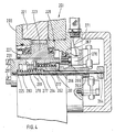
- Fig. 2 einen demgegenüber in größerem Maßstab gezeichneten Schnitt längs der Schnittlinie II-II von Fig. 1, wobei die Werkzeugscheibe mit strichpunktieren Linien in abgebrochener Darstellung angedeutet ist, und
- Fig. 3 und 4 der Fig. 2 ähnliche, jedoch in noch größerem Maßstab dargestellte Schnitte eines zweiten bzw. eines dritten Ausführungsbeispiels des Werkzeugrevolvers.
- Von einem Werkzeugrevolver für die Verwendung bei einer Drehmaschine oder einer NC-Bearbeitungseinheit zeigt Fig. 1 in Vorderansicht einen Revolverkopf 1 in Form eines im großen und ganzen kreiszylindrischen Gehäuses, das beispielsweise auf einem Kreuzsupport einer betreffenden Drehmaschine oder einem Ständer oder Schlitten einer Bearbeitungseinheit anbringbar ist. Der Revolverkopf 1 weist eine kreisrunde vordere Planfläche 3 auf, an der eine in Fig. 1 nicht dargestellte Werkzeugscheibe, die lediglich in Fig. 2 angedeutet und mit 5 bezeichnet ist, in üblicher Weise drehbar anbringbar ist, wobei die Werkzeugscheibe 5 durch einen Zentrierzapfen 7 zentriert ist, der aus der Planfläche 3 etwas vorspringt und eine zentrale Revolverachse 8 definiert. Die Werkzeugscheibe 5 ist in bekannter Weise am Revolverkopf 1 in Drehschritten weiterschaltbar, deren Anzahl und Drehwinkel entsprechend der Anzahl und Lageanordnung von Werkzeugstationen der Werkzeugscheibe 5 gewählt sind.
- Bei den Werkzeugstationen der Werkzeugscheibe 5 handelt es sich um Werkzeugaufnahme 11 (s. Fig. 2), in denen Werkzeughalter mit ihrem Aufnahmeschaft 12 so aufnehmbar sind, daß die Längsachse des betreffenden Aufnahmeschafts 12 achsparallel zur Revolverachse 8 verläuft. Der in Fig. 2 gezeigte Aufnahmeschaft 12 gehört zu einem Werkzeughalter, der mit einem Rotationswerkzeug bestückt ist. Dieses ist mittels einer im Aufnahmeschaft 12 koaxial drehbar gelagerten Antriebswelle 13 antreibbar, deren Endabschnitt 15 in dem der Planfläche 3 zugekehrten Endbereich 17 der Werkzeugaufnahme 11 frei zugänglich ist, so daß der Endabschnitt 15 der Antriebswelle 13 auf nachstehend zu beschreibende Weise mit einer Dreh- Antriebseinrichtung verbindbar ist.
- Diese Antriebseinrichtung weist, wie aus Fig. 1 zu ersehen ist, einem am Revolverkopf 1 seitlich befestigten Getriebemotor 19 auf, dessen Abtriebsrad 20 (Fig. 1) mit der äußeren Stirnverzahnung eines Zahnringes 21 kämmt, der im Revolverkopf 1 in geringem Abstand von dessen vorderer Planfläche 3 um die Revolverachse 8 drehbar gelagert ist.
- Ein mit dem Zahnring 21 kämmendes, von diesem angetriebenes Zahnritzel 23 ist bei dem gezeigten Ausführungsbeispiel im Revolverkopf 1 an einer dem Rad 20 in etwa diametral gegenüberliegenden Stelle drehbar und axial unverschiebbar so gelagert, daß seine Drehachse 25 achsparallel zur Revolverachse 8 verläuft und zur Revolverachse 8 den gleichen Radialabstand besitzt wie die Längsachsen der Werkzeugaufnahmen 11 der Werkzeugscheibe 5. Das Zahnritzel 23 besitzt beidseits neben seines
- Verzahnungsteils in Axialrichtung verlängerte Nabenteile 27 und 28, deren Außenmantelflächen mit Wälzlagern 29 und 30 zur Lagerung des Zahnritzels 23 zusammenwirken. Wegen des Vorhandenseins der langgestreckten Nabenteile 27 und 28 hat eine durchgehende koaxiale Nabenbohrung eine verhältnismäßig große axiale Länge, verglichen mit der axialen Erstreckung des Verzahnungsabschnittes des Zahnritzels 23.
- Um die Drehbewegung des im Betrieb dauernd über den Zahnring 21 angetriebenen Zahnritzels 23 wahlweise auf den Endabschnitt 15 der Antriebswelle 13 eines Werkzeugs in einer auf die Drehachse 25 ausgerichteten Werkzeugaufnahme 11 zu übertragen, ist ein längs der Drehachse 25 wahlweise verschiebbares Schieberad vorhanden, das mit dem Zahnritzel 23 auf Drehung verbunden ist. Beim in Fig. 1 und 2 gezeigten Ausführungsbeispiel ist das Schieberad in Form einer kreiszylindrischen Hülse 31 ausgebildet, deren Außenseite mit einer geraden Keilverzahnung 33 versehen ist. Die Hülse 31 ist in der Nabenbohrung des Zahnritzels 23 axial verschiebbar gelagert, wobei die äußere Keilverzahnung 33 in die Hülse 31 in Keilnuten 35 der Nabenbohrung des Zahnritzels 23 geführt ist, so daß Hülse 31 und Zahnritzel 23 formschlüssig auf Drehung verbunden sind.
- In ihrem der Planfläche 3 zugekehrten vorderen Endabschnitt weist die Hülse 31 an ihrer Innenwandung Keilnuten 37 auf. Durch Vorschieben der Hülse 31 längs der Drehachse 25 in Richtung auf die Werkzeugscheibe 5 hin kommt eine äußere Keilverzahnung 39 am Endabschnitt 15 der Antriebswelle 13 eines in der Werkzeugaufnahme 11 angeordneten Rotationswerkzeugs in Kupplungseingriff mit den Keilnuten 37 in der Hülse 31. Für das wahlweise Verschieben der Hülse 31 zwischen deren in Fig. 2 gezeigter zurückgezogener Entkuppelstellung und der vorgeschobenen Kupplungsstellung, in der die Keilnuten 37 der Hülse 31 mit der Keilverzahnung 39 am Endabschnitt 15 der Antriebswelle 13 in Eingriff sind, ist eine Steuereinrichtung vorgesehen.
- Diese Steuereinrichtung weist bei dem Ausführungsbeispiel gemäß Fig. 1 und 2 einen in Fig. 1 als Ganzes mit 41 bezeichneten Stellantrieb auf, der, dem Getriebemotor 19 in etwa gegenüberliegend, an der Außenseite des Revolverkopfs 1 angeordnet ist. Der Stellantrieb 41 weist einen hydraulisch betätigbaren Arbeitszylinder 42 auf, mittels dessen ein Schalthebel 43 um einen Schwenkzapfen 44 schwenkbar ist. Der Schalthebel 43, von dem in Fig. 2 lediglich das gegabelte Ende 45 zu sehen ist, das als Schaltgabel dient, wirkt mit seitlichen Zapfen 47 eines in die Bohrung der Hülse 31 ragenden Steuerdornes 49 zusammen. Der Steuerdorn 49 erstreckt sich zur Drehachse 25 koaxial, ist jedoch wegen des Eingriffs zwischen seinen seitlichen Zapfen 47 und den als Schaltgabel dienenden Enden 45 des Schalthebels 43 nicht um die Achse 25 drehbar. Die Hülse 31 besitzt im Anschluß an den die Keilnuten 37 aufweisenden Bohrungsabschnitt einen erweiterten Bohrungsabschnitt 51, in dem zwei auf dem Steuerdorn 49 sitzende Wälzlager 53 angeordnet sind. Zwischen dem den Keilnuten 37 benachbarten vorderen Wälzlager 53 und der Innenschulter am Ende eines erweiterten Bohrungsabschnittes 51 sitzt ein topfförmiger Mitnehmerkörper 54, der in Zusammenwirkung mit dem Außenring des zugeordneten Wälzlagers 53 und der Innenschulter der Hülse 31 diese bei einer Axialverschiebung des Steuerdorns 49 in Richtung auf die Werkzeugscheibe 5 hin mitzunehmen und in die Kupplungsstellung zu verschieben vermag.
- Zwischen den beiden Wälzlagern 53 ist eine Distanzierhülse 55 eingefügt. Der Außenring des den seitlichen Zapfen 47 benachbarten Wälzlagers 53 ist durch einen Sicherungsring 57 in Axialrichtung festgelegt. Auf diese Weise wird eine Verschiebebewegung des Steuerdorns 49 in Fig. 2 nach rechts auf die Hülse 31 übertragen, um diese in die in Fig. 2 gezeigte Endkuppelstellung zu bewegen. Es versteht sich, daß der den Schalthebel 43 bewegende Stellantrieb 41 der Steuereinrichtung anstelle eines hydraulischen Arbeitszylinders 42 einen anderen Kraftantrieb aufweisen könnte, beispielsweise einen Steuermagneten oder einen pneumatischen Antrieb.
- Wie weiter oben beschrieben wurde, ist beim hier erläuterten Ausführungsbeispiel der Getriebemotor 19 mit dem den Zahnring 21 antreibenden Rad 20 auf der einen Seite neben dem Revolverkopf 1 angeordnet und das vom Zahnring 21 getriebe Zahnritzel 23 befindet sich in dem zum Rad 20 in etwa diametral gegenüberliegenden Seitenbereich des Revolverkopfes 1. Eine solche Lagebeziehung ist jedoch nicht zwingend. Ein Vorteil der Erfindung besteht darin, daß die Positionen des Antriebsmotors (Getriebemotor 19) und des angetriebenen Zahnritzels 23, dessen Achse 25 die Arbeitsposition des anzutreibenden Rotationswerkzeuges bestimmt, frei wählbar sind. So könnte beispielsweise, wenn dies für einen betreffenden Anwendungsfall beispielsweise aus Platzgründen oder aus durch die Bauart der zugeordneten Maschine bedingten Gesichtspunkten zweckmäßig ist, der Motor and der Oberseite des Revolverkopfes 1 und das die Arbeitsposition definierende Zahnritzel 23 an der Unterseite des Revolverkopfes 1 angeordnet sein. Es ist auch möglich, mehr als eine Arbeitsposition vorzusehen, indem beispielsweise der Motor an der Ober- oder Unterseite des Revolverkopfes 1 angeordnet wird und zu beiden Seiten des Motors je ein Zahnritzel 23 mit zugeordneten Schalt- und Steuereinrichtungen vorgesehen wird.
- In Fig. 3, die Erläuterung eines zweiten Ausführungsbeispiels eines Werkzeugsrevolvers dient, sind Teile, die solchen des erstbeschriebenen Ausführungsbeispiels entsprechen, mit demgegenüber um 100 vergrößerten Bezugszahlen bezeichnet. Dieses zweite Auführungsbeispiel unterscheidet sich vom erstbeschriebenen Ausführungsbeispiel in der Hauptsache durch einen andersartigen Aufbau der Steuereinrichtung für die axialen Verschiebebewegungen der Hülse 131 längs der Drehachse 125. Bei dem Ausführungsbeispiel gemäß Fig. 3 ist die Hülse 131 normalerweise durch eine Ausrückfeder 161 in die in Fig. 3 gezeigte Entkuppelstellung vorgespannt. Die Ausrückfeder 161 stützt sich einerseits am inneren Ende einer Steuertrommel 162 ab und drückt mit ihrem anderen Ende auf ein Gleitstück 163, das auf einer zur Drehachse 125 konzentrischen Welle 164 verschiebbar ist. Das Gleitstück 163 weist eine Umfangsnut 165 auf, in die ein in der Wandung der Hülse 131 sitzender Steuerstift 166 eingreift, wobei eine Begrenzungsschulter der Umfangsnut 165 durch die Kraft der Ausrückfeder 161 in Anlage mit dem Steuerstift 166 gehalten ist. Die Kraft der Ausrückfeder 161 wirkt also über das Gleitstück 163 auf den Steuerstift 166 und sucht diesen nach rechts (Blickrichtung gemäß Fig. 3) zu verschieben.
- Die Steuertrommel 162 ist mittels eines auch Axialkräfte aufnehmenden Wälzlagers 167 um die Drehachse 125 drehbar gelagert, jedoch axial unverschiebbar, und ist mit der Hülse 131 reibungsschlüssig gekuppelt, die über ihre äußere Keilverzahnung 133 mit dem Zahnritzel 123 auf Drehung verbunden ist. Genauer gesagt bildet ein Dichtungsring 168, der zwischen dem erweiterten inneren Bohrungsabschnitt 151 der Hülse 131 und dem darin befindlichen Umfangsabschnitt der Steuertrommel 162 angeordnet ist, einen Reibschluß, der die Steuertrommel 162 normalerweise mit der Hülse 131 mitdreht.
- An ihrem hinteren, dem Wälzlager 167 benachbarten Ende 169, wirkt die Steuertrommel 162 mit einer Magnetbremse 170 zusammen, die über ein Erregerkabel 171 wahlweise aktivierbar ist. Bei Aktivierung vermag die Magnetbremse 170 ein Bremsmoment zu erzeugen, das die Mitnahmewirkung des Reibschlusses zwischen der Hülse 131 und der Steuertrommel 162 übersteigt.
- Die Wirkungsweise des Ausführungsbeispiels gemäß Fig. 3 ist folgende: Wie gesagt, wirkt die Kraft der Ausrückfeder 161 über das Gleitstück 163 auf den Steuerstift 166 ein. Da dieser in der Wandung der Bohrung der Hülse 131 sitzt, ist die Hülse 131 normalerweise durch die Kraft der Ausrückfeder 161 in der dargestellten Entkuppelstellung. Wie aus Fig. 3 zu ersehen ist, erstreckt sich der Steuerstift 166 durch eine Ausnehmung 172 in der Wandung der Steuertrommel 162 hindurch. Diese Ausnehmung 172 hat, was in Fig. 3 nicht erkennbar ist, eine zur Drehachse 125 schräge Erstreckung, genauer gesagt, die Form eines spiral- oder schraubenförmig verlaufenden Schlitzes. Bei nicht aktivierter Magnetbremse 170, wenn also die Steuertrommel 162 mit der Hülse 131 frei drehbar ist, liegt der Steuerstift 166 unter der Einwirkung der Ausrückfeder 161 an dem in Fig. 3 rechts gelegenen Ende der Ausnehmung 172 an. Wird nun die Magnetbremse 170 aktiviert, so bleibt die Steuertrommel 162 gegenüber der Drehbewegung der Hülse 131 zurück, was bewirkt, daß der Steuerstift 166 in der als Spiralschlitz oder Schraubenschlitz gestalteten Ausnehmung 172 zu deren in der Zeichnung links gelegenem Ende 173 wandert. Bei dieser Bewegung des Steuerstifts 166 ergibt sich eine entsprechende axiale Verschiebebewegung der Hülse 131 in die vorgeschobene Kupplungsstellung. Wird die Magnetbremse 170 wieder inaktiviert, dann wandert der Steuerstift 166 in der Ausnehmung 172 unter der Einwirkung der Feder 161 wieder in die in Fig. 3 gezeigte Endstellung, wobei die Hülse 131 in die Entkuppelstellung bewegt wird.
- Teile des in Fig. 4 dargestellten dritten Ausführungsbeispiels, die solchen des ersten Ausführungsbeispiels oder des zweiten Ausführungsbeispiels entsprechen sind mit demgegenüber um 200 bzw. um 100 vergrößerten Bezugszahlen bezeichnet. Auch bei diesem Ausführungsbeispiel ist eine mittels eines Wälzlagers 267 bezüglich der Drahachse 225 drehbar und axial unverschiebbar gelagerte Steuertrommel 262 vorhanden, deren inneres Ende 269 mit einer Magnetbremse 270 zusammenwirkt. Die Steuertrommel 262 besitzt ebenfalls eine Ausnehmung 272 in Form eines Spiral- oder Schraubenschlitzes. Die Ausnehmung 272 ist von einem Steuerstift 266 durchgriffen, der durch die Kraft einer Ausrückfeder 261 normalerweise in dem in Fig. 4 rechts gelegenen Endteil der Ausnehmung 272 gehalten ist. Im Unterschied zum Ausführungsbeispiel gemäß Fig. 3 ist der Steuerstift 266 jedoch nicht in der Wandung der Hülse 231 gelagert, sondern an dem auf der Welle 264 verschiebbar gelagerten Gleitstück 263. Die Axialstellung des Gleitstücks 263 hängt also von der Position des Steuerstiftes 266 in der Ausnehmung 272 ab.
- Die Aktivierung der Magnetbremse 270 bewirkt ein Zurückbleiben der Drehbewegung der Steuertrommel 262 gegenüber der Hülse 231 und dem Gleitstück 263, das mit der Hülse 231 mittels eines Mitnehmerstifts 277 auf Drehung verbunden ist, der in einen geraden, achsparallel verlaufenden Mitnehmerschlitz 278 der Hülse 231 eingreift. Bei der in Fig. 4 gezeigten Entkuppelstellung, bei der der Steuerstift 266 an dem in der Zeichnung rechts gelegenen Ende der Ausnehmung 272 anliegt, befindet sich der Mitnehmerstift 277 am in der Zeichnung rechts liegenden inneren Ende 281 des Mitnehmerschlitzes 278 und blockiert dadurch eine Verschiebebewegung der Hülse 231 nach links in die vorgeschobene Kupplungsstellung, obwohl die Hülse 231 durch eine Einrückfeder 283 für diese Bewegung in die Kupplungsstellung vorgespannt ist. Die Einrückfeder 283 sitzt auf der Welle 264 und stützt sich einerseits am Gleitstück 263 und andererseits am vorderen geschlossenen Ende der Innenbohrung der Hülse 231 ab. Wird die Magnetbremse 270 aktiviert, so wandert der Steuerstift 266 innerhalb der Ausnehmung 272, wobei das Gleitstück 263 gegen die Kraft der Ausrückfeder 261 in der Zeichnung nach links verschoben wird. Durch die entsprechende Bewegung des Mitnehmerstifts 277 nach links ist die Hülse 231 freigegeben, so daß sie sich unter der Einwirkung der Einrückfeder 283 ebenfalls nach links in die Kupplungsstellung bewegen kann, wobei äußere Mitnehmerlappen 287 der Hülse 231 mit zugeordneten Mitnehmergliedern an der Antriebswelle eines entsprechenden Rotationswerkzeuges in Kupplungseingriff kommen. Bei dem Ausführungsbeispiel gemäß Fig. 4 handelt es sich also um das Prinzip einer mittels der Einrückfeder 283 angefederten Kupplung für Werkzeugantriebe gemäß den VDMA-Richtlinien.
- Alle in der vorstehenden Beschreibung erwähnten sowie auch die nur allein aus der Zeichnung entnehmbaren Merkmale sind als weitere Ausgestaltungen Bestandteile der Erfindung, auch wenn sie nicht besonders hervorgehoben und insbesondere nicht in den Ansprüchen erwähnt sind.
Claims (8)
Applications Claiming Priority (2)
| Application Number | Priority Date | Filing Date | Title |
|---|---|---|---|
| DE8710865U DE8710865U1 (de) | 1987-08-08 | 1987-08-08 | Werkzeugrevolver für Werkzeugmaschinen |
| DE8710865U | 1987-08-08 |
Publications (3)
| Publication Number | Publication Date |
|---|---|
| EP0302998A2 true EP0302998A2 (de) | 1989-02-15 |
| EP0302998A3 EP0302998A3 (en) | 1989-12-20 |
| EP0302998B1 EP0302998B1 (de) | 1992-07-01 |
Family
ID=6810925
Family Applications (1)
| Application Number | Title | Priority Date | Filing Date |
|---|---|---|---|
| EP88106128A Expired - Lifetime EP0302998B1 (de) | 1987-08-08 | 1988-04-18 | Werkzeugrevolver für Werkzeugmaschinen |
Country Status (3)
| Country | Link |
|---|---|
| EP (1) | EP0302998B1 (de) |
| DE (2) | DE8710865U1 (de) |
| ES (1) | ES2032893T3 (de) |
Cited By (6)
| Publication number | Priority date | Publication date | Assignee | Title |
|---|---|---|---|---|
| EP0455286A3 (en) * | 1990-04-30 | 1992-06-10 | Baruffaldi S.P.A. | Coupling device for the transmission of the movement to toolholder units of automatic turrets |
| US5332344A (en) * | 1992-08-31 | 1994-07-26 | Sauter Feinmechanik Gmbh | Spindle head for tool turret |
| DE10125722A1 (de) * | 2001-05-18 | 2002-12-05 | Sauter Kg Feinmechanik | Werkzeugrevolver |
| WO2003084714A1 (en) * | 2002-04-08 | 2003-10-16 | Duplomatic Automazione S.P.A. | Driving system for rotary tools in a tool holder turret |
| CN101829792A (zh) * | 2010-04-15 | 2010-09-15 | 沈阳机床(集团)设计研究院有限公司 | Y轴双伺服动力刀架 |
| CN117381504A (zh) * | 2023-11-16 | 2024-01-12 | 江苏美事科电机制造有限公司 | 一种数控车床非圆和偏心圆车削的进给刀架 |
Families Citing this family (1)
| Publication number | Priority date | Publication date | Assignee | Title |
|---|---|---|---|---|
| DE8710865U1 (de) * | 1987-08-08 | 1987-09-24 | Sauter Feinmechanik GmbH, 7430 Metzingen | Werkzeugrevolver für Werkzeugmaschinen |
Family Cites Families (10)
| Publication number | Priority date | Publication date | Assignee | Title |
|---|---|---|---|---|
| US2677169A (en) * | 1951-02-05 | 1954-05-04 | Stephen F Cybulski | Indexing device |
| DE1253995B (de) * | 1964-07-21 | 1967-11-09 | Magdeburg Werkzeugmasch | Elektro-hydraulische Schwenk- und Spanneinrichtung fuer einen Revolverkopf |
| JPS51126586A (en) * | 1975-04-28 | 1976-11-04 | Toyoda Mach Works Ltd | Device for stopping the spindle of turret type machining center in fix ed phase |
| DE2656608A1 (de) * | 1975-12-22 | 1977-06-30 | Smt Machine Co Ab | Werkzeugrevolver |
| DE3202042C2 (de) * | 1982-01-23 | 1987-01-22 | G. Boley GmbH & Co, Werkzeugmaschinenfabrik, 7300 Esslingen | Werkzeugrevolver für Werkzeugmaschinen, insbesondere Drehmaschinen |
| GB2126134B (en) * | 1982-09-03 | 1986-01-08 | 600 Group P L C The | Common turret indexing and tool holder drive mechanism |
| FR2539830B1 (fr) * | 1983-01-26 | 1989-03-17 | Vinel Bernard | Dispositif d'embrayage-debrayage applicable aux moyeux de roues de vehicules automobiles, en particulier les vehicules du type a quatre roues motrices ou plus |
| DE3668565D1 (de) * | 1985-08-12 | 1990-03-08 | Schaeublin Sa | Vorrichtung zum antreiben von werkzeugtraegern in einer werkzeugmaschine. |
| IT206882Z2 (it) * | 1985-09-11 | 1987-10-12 | Baruffaldi Frizioni Spa | Dispotivo per la rotazione di utensili radiali in posizioni prefissate in torrette girevoli di torni automatici. |
| DE8710865U1 (de) * | 1987-08-08 | 1987-09-24 | Sauter Feinmechanik GmbH, 7430 Metzingen | Werkzeugrevolver für Werkzeugmaschinen |
-
1987
- 1987-08-08 DE DE8710865U patent/DE8710865U1/de not_active Expired
-
1988
- 1988-04-18 EP EP88106128A patent/EP0302998B1/de not_active Expired - Lifetime
- 1988-04-18 ES ES198888106128T patent/ES2032893T3/es not_active Expired - Lifetime
- 1988-04-18 DE DE8888106128T patent/DE3872466D1/de not_active Expired - Lifetime
Cited By (7)
| Publication number | Priority date | Publication date | Assignee | Title |
|---|---|---|---|---|
| EP0455286A3 (en) * | 1990-04-30 | 1992-06-10 | Baruffaldi S.P.A. | Coupling device for the transmission of the movement to toolholder units of automatic turrets |
| US5332344A (en) * | 1992-08-31 | 1994-07-26 | Sauter Feinmechanik Gmbh | Spindle head for tool turret |
| DE10125722A1 (de) * | 2001-05-18 | 2002-12-05 | Sauter Kg Feinmechanik | Werkzeugrevolver |
| US6722005B2 (en) | 2001-05-18 | 2004-04-20 | Sauter Feinmechanik Gmbh | Turret |
| WO2003084714A1 (en) * | 2002-04-08 | 2003-10-16 | Duplomatic Automazione S.P.A. | Driving system for rotary tools in a tool holder turret |
| CN101829792A (zh) * | 2010-04-15 | 2010-09-15 | 沈阳机床(集团)设计研究院有限公司 | Y轴双伺服动力刀架 |
| CN117381504A (zh) * | 2023-11-16 | 2024-01-12 | 江苏美事科电机制造有限公司 | 一种数控车床非圆和偏心圆车削的进给刀架 |
Also Published As
| Publication number | Publication date |
|---|---|
| EP0302998A3 (en) | 1989-12-20 |
| DE8710865U1 (de) | 1987-09-24 |
| DE3872466D1 (de) | 1992-08-06 |
| ES2032893T3 (es) | 1993-03-01 |
| EP0302998B1 (de) | 1992-07-01 |
Similar Documents
| Publication | Publication Date | Title |
|---|---|---|
| EP1224048B1 (de) | Werkzeughalter | |
| DE1752832C3 (de) | Vorrichtung zur lösbaren Verbindung eines Werkzeugs mit der Spindel einer Werkzeugmaschine | |
| DE3216891C2 (de) | ||
| DE4201849C1 (de) | ||
| DE1552227C3 (de) | Werkzeugmaschine mit einem Arbeitsmotor für Spindel- und Schlittenantrieb und einem Eilgangmotor für den Schlittenantrieb | |
| EP0415271B1 (de) | Werkzeugrevolver für Werkzeugmaschinen | |
| DE7522786U (de) | Hilfsstock mit drehantreibbar umlaufender klemmeinrichtung | |
| EP0302998B1 (de) | Werkzeugrevolver für Werkzeugmaschinen | |
| DE2225476A1 (de) | Manipulator | |
| DE3244019A1 (de) | Automatische handhabungsvorrichtung fuer industrielle arbeiten | |
| EP0145703B1 (de) | Querschlitten für eine Drehmaschine | |
| DE2156153B2 (de) | ||
| DE3231782A1 (de) | Nc-gesteuerte revolver-drehmaschine | |
| DE3524879C1 (de) | Stoßfräsmaschine zum Bearbeiten der Stirnflächen der Zähne von Zahnrädern oder dgl. verzahnten Werkstücken | |
| EP0411387A1 (de) | C-Achsgetriebe | |
| DE872717C (de) | Antriebsvorrichtung fuer den Vorschub und Ruecklauf des Schlittens eines Bohr- und Fraeskopfes | |
| DE4308419A1 (de) | Werkzeugrevolver | |
| DE1294143B (de) | Durch Kraftantrieb schaltbarer Revolverkopf fuer Drehmaschinen u. dgl. | |
| DE1300417B (de) | Bohrwerk od. dgl. mit einer in der Hauptspindel verschiebbar gelagerten hohlen Bohrspindel | |
| DE3304980A1 (de) | Vorrichtung und verfahren zum herstellen und bearbeiten von zahnraedern | |
| DE685111C (de) | Revolverdrehbank | |
| DE4341142C2 (de) | Gewindeschneidapparat | |
| DE1302431B (de) | ||
| DE2332173A1 (de) | Transfer-werkzeugmaschine mit mehreren drehbaren spannfuttern fuer die werkstuecke | |
| DE692668C (de) | Getriebe zum selbsttaetigen Umschalten von Werkzeugschlitten, insbesondere auf Drehbaenken zum Ab- und Einstecken von Eisenbahnradachsen |
Legal Events
| Date | Code | Title | Description |
|---|---|---|---|
| PUAI | Public reference made under article 153(3) epc to a published international application that has entered the european phase |
Free format text: ORIGINAL CODE: 0009012 |
|
| AK | Designated contracting states |
Kind code of ref document: A2 Designated state(s): DE ES FR GB IT |
|
| PUAL | Search report despatched |
Free format text: ORIGINAL CODE: 0009013 |
|
| AK | Designated contracting states |
Kind code of ref document: A3 Designated state(s): DE ES FR GB IT |
|
| 17P | Request for examination filed |
Effective date: 19900309 |
|
| 17Q | First examination report despatched |
Effective date: 19910617 |
|
| ITF | It: translation for a ep patent filed | ||
| GRAA | (expected) grant |
Free format text: ORIGINAL CODE: 0009210 |
|
| STAA | Information on the status of an ep patent application or granted ep patent |
Free format text: STATUS: THE PATENT HAS BEEN GRANTED |
|
| AK | Designated contracting states |
Kind code of ref document: B1 Designated state(s): DE ES FR GB IT |
|
| ET | Fr: translation filed | ||
| GBT | Gb: translation of ep patent filed (gb section 77(6)(a)/1977) | ||
| REF | Corresponds to: |
Ref document number: 3872466 Country of ref document: DE Date of ref document: 19920806 |
|
| REG | Reference to a national code |
Ref country code: ES Ref legal event code: FG2A Ref document number: 2032893 Country of ref document: ES Kind code of ref document: T3 |
|
| PLBI | Opposition filed |
Free format text: ORIGINAL CODE: 0009260 |
|
| 26 | Opposition filed |
Opponent name: BARUFFALDI S.P.A. Effective date: 19930331 |
|
| PLBG | Opposition deemed not to have been filed |
Free format text: ORIGINAL CODE: 0009274 |
|
| 26D | Opposition deemed not to have been filed | ||
| REG | Reference to a national code |
Ref country code: GB Ref legal event code: IF02 |
|
| PGFP | Annual fee paid to national office [announced via postgrant information from national office to epo] |
Ref country code: GB Payment date: 20050316 Year of fee payment: 18 |
|
| PGFP | Annual fee paid to national office [announced via postgrant information from national office to epo] |
Ref country code: ES Payment date: 20050404 Year of fee payment: 18 |
|
| PGFP | Annual fee paid to national office [announced via postgrant information from national office to epo] |
Ref country code: FR Payment date: 20050429 Year of fee payment: 18 |
|
| PG25 | Lapsed in a contracting state [announced via postgrant information from national office to epo] |
Ref country code: GB Free format text: LAPSE BECAUSE OF NON-PAYMENT OF DUE FEES Effective date: 20060418 |
|
| PG25 | Lapsed in a contracting state [announced via postgrant information from national office to epo] |
Ref country code: ES Free format text: LAPSE BECAUSE OF NON-PAYMENT OF DUE FEES Effective date: 20060419 |
|
| GBPC | Gb: european patent ceased through non-payment of renewal fee |
Effective date: 20060418 |
|
| REG | Reference to a national code |
Ref country code: FR Ref legal event code: ST Effective date: 20061230 |
|
| PGFP | Annual fee paid to national office [announced via postgrant information from national office to epo] |
Ref country code: DE Payment date: 20070404 Year of fee payment: 20 |
|
| REG | Reference to a national code |
Ref country code: ES Ref legal event code: FD2A Effective date: 20060419 |
|
| PGFP | Annual fee paid to national office [announced via postgrant information from national office to epo] |
Ref country code: IT Payment date: 20070626 Year of fee payment: 20 |
|
| PG25 | Lapsed in a contracting state [announced via postgrant information from national office to epo] |
Ref country code: FR Free format text: LAPSE BECAUSE OF NON-PAYMENT OF DUE FEES Effective date: 20060502 |