EP0302565B1 - Machining tool - Google Patents
Machining tool Download PDFInfo
- Publication number
- EP0302565B1 EP0302565B1 EP88201645A EP88201645A EP0302565B1 EP 0302565 B1 EP0302565 B1 EP 0302565B1 EP 88201645 A EP88201645 A EP 88201645A EP 88201645 A EP88201645 A EP 88201645A EP 0302565 B1 EP0302565 B1 EP 0302565B1
- Authority
- EP
- European Patent Office
- Prior art keywords
- cutting body
- radiation
- tool
- grinding wheel
- selectively
- Prior art date
- Legal status (The legal status is an assumption and is not a legal conclusion. Google has not performed a legal analysis and makes no representation as to the accuracy of the status listed.)
- Expired - Lifetime
Links
Images


Classifications
-
- B—PERFORMING OPERATIONS; TRANSPORTING
- B24—GRINDING; POLISHING
- B24D—TOOLS FOR GRINDING, BUFFING OR SHARPENING
- B24D7/00—Bonded abrasive wheels, or wheels with inserted abrasive blocks, designed for acting otherwise than only by their periphery, e.g. by the front face; Bushings or mountings therefor
-
- B—PERFORMING OPERATIONS; TRANSPORTING
- B23—MACHINE TOOLS; METAL-WORKING NOT OTHERWISE PROVIDED FOR
- B23Q—DETAILS, COMPONENTS, OR ACCESSORIES FOR MACHINE TOOLS, e.g. ARRANGEMENTS FOR COPYING OR CONTROLLING; MACHINE TOOLS IN GENERAL CHARACTERISED BY THE CONSTRUCTION OF PARTICULAR DETAILS OR COMPONENTS; COMBINATIONS OR ASSOCIATIONS OF METAL-WORKING MACHINES, NOT DIRECTED TO A PARTICULAR RESULT
- B23Q17/00—Arrangements for observing, indicating or measuring on machine tools
- B23Q17/09—Arrangements for observing, indicating or measuring on machine tools for indicating or measuring cutting pressure or for determining cutting-tool condition, e.g. cutting ability, load on tool
-
- B—PERFORMING OPERATIONS; TRANSPORTING
- B24—GRINDING; POLISHING
- B24B—MACHINES, DEVICES, OR PROCESSES FOR GRINDING OR POLISHING; DRESSING OR CONDITIONING OF ABRADING SURFACES; FEEDING OF GRINDING, POLISHING, OR LAPPING AGENTS
- B24B33/00—Honing machines or devices; Accessories therefor
- B24B33/08—Honing tools
-
- B—PERFORMING OPERATIONS; TRANSPORTING
- B24—GRINDING; POLISHING
- B24B—MACHINES, DEVICES, OR PROCESSES FOR GRINDING OR POLISHING; DRESSING OR CONDITIONING OF ABRADING SURFACES; FEEDING OF GRINDING, POLISHING, OR LAPPING AGENTS
- B24B49/00—Measuring or gauging equipment for controlling the feed movement of the grinding tool or work; Arrangements of indicating or measuring equipment, e.g. for indicating the start of the grinding operation
- B24B49/18—Measuring or gauging equipment for controlling the feed movement of the grinding tool or work; Arrangements of indicating or measuring equipment, e.g. for indicating the start of the grinding operation taking regard of the presence of dressing tools
- B24B49/183—Wear compensation without the presence of dressing tools
-
- Y—GENERAL TAGGING OF NEW TECHNOLOGICAL DEVELOPMENTS; GENERAL TAGGING OF CROSS-SECTIONAL TECHNOLOGIES SPANNING OVER SEVERAL SECTIONS OF THE IPC; TECHNICAL SUBJECTS COVERED BY FORMER USPC CROSS-REFERENCE ART COLLECTIONS [XRACs] AND DIGESTS
- Y10—TECHNICAL SUBJECTS COVERED BY FORMER USPC
- Y10T—TECHNICAL SUBJECTS COVERED BY FORMER US CLASSIFICATION
- Y10T407/00—Cutters, for shaping
- Y10T407/27—Cutters, for shaping comprising tool of specific chemical composition
Definitions
- the invention relates to a honing tool or a grinding wheel, formed by a cutting body and a cutting body carrier carrying the cutting body and a measuring device for measuring the wear of such tools.
- Another possibility is to monitor the delivery route with electronic mechanical or electronic-hydraulic tool delivery.
- this only means an indirect control of the wear on the cutting surface of a honing stone. If the infeed is carried out in steps by a certain number of impulses, then a number of additional impulse, which can also be preset, can be provided after a presettable number of machining cycles, depending on the assumed wear.
- a number of additional impulse which can also be preset, can be provided after a presettable number of machining cycles, depending on the assumed wear.
- Even such a device does not provide actual wear monitoring, but only wear compensation. It is only the sum of the additional pulses required for compensation and the comparison with an empirically predetermined usable height of the cutting surface of a honing stone, however, which gives the information which can be used by a machine control system as to whether a honing stone has to be replaced.
- EP-A-0 225 300 describes an indexable insert in which a radiation-opaque layer is applied to a substrate that emits radiation. With increasing wear, the radiation-emitting substrate is increasingly exposed in the area of the open area. The radiation emitted by the substrate is determined as a measure of the wear. In addition, it is known from this document to determine small-area wear of the crater wear type on the cutting edge itself. Direct wear monitoring via free-space wear is not applicable to honing stones, since they are in total contact with the workpiece and have no free areas on which wear could be determined in this way.
- DD-A-222 414 The same applies to DD-A-222 414.
- a method for wear detection on a turning tool in which a punctiform radioactive marking is applied to the free surface and / or the rake surface of the tool. In the event of wear, the radioactive marking is also removed. The resulting change in radiation is used to measure wear. Such a wear measurement is not applicable to honing stones, because of the not uncritical radiation exposure of the workplace, because a flat monitoring of the cutting body is not possible.
- a drill is known from US Pat. No. 4,420,253, in the shaft of which a glass fiber is embedded. One end of the glass fiber is illuminated by a light source. The other end extends into the shaft and ends at a certain distance from the cutting edge. After removal of this material lying between the fiber end and the cutting edge, the light is registered in a detector arranged below the drill. With such a method, wear monitoring of a honing stone is not possible, since the entire surface of the cutting body could not be monitored without extreme effort.
- a measuring device for measuring the wear of a knife for cutting semiconductor wafers is known.
- the light beam emanating from a transmitter arrangement and reflected by the knife is registered in a detector.
- the wear of the knife body changes the reflective behavior of the knife. This also changes the intensity of the reflected light beam.
- This measuring device has the disadvantage that it is very sensitive to scattered light from other radiation sources. As stated in this transcript, the measuring device works not if the knife is wetted by rinsing and / or cooling media.
- the measuring device also only delivers a signal which - due to the rotation of the knife - corresponds to wear averaged over a partial area of the knife.
- US-A-40 31 368 describes a measuring device on a machine tool in which a laser beam is guided over the tool. The reflection of the laser beam is registered in a receiver arrangement and forwarded to an evaluation device. This evaluation device calculates the wear from the optical measurement data in connection with other parameters (e.g. workpiece dimensions, vibrations, surface roughness etc.).
- This measuring device uses costly and maintenance-intensive devices, e.g. a laser resonator in advance, the applicability to the determination of wear of honing stones does not apply for the reasons given above.
- the "cutting body” is understood to mean the cutting surface of a honing stone or grinding wheel formed by binding material with diamond grain.
- the honing stone should also be designed in such a way that the monitoring of inaccuracies in the cutting surface is independent, ie it should be possible to determine exactly the right time for changing the tool despite such inaccuracies in the height of the cutting surface.
- the wear measurement on the honing stone by means of the measuring device described should still work even if the honing stone is wetted by flushing or cooling media (eg honing oil). Furthermore, a suitable measuring device for measuring the wear of such a honing or grinding tool is to be provided, with which the state of wear can be detected simply and directly, ie it can be determined when the cutting body is worn and a replacement is necessary.
- flushing or cooling media eg honing oil
- a honing tool or a grinding wheel of the type mentioned at the outset in which an electromagnetic radiation at a specific wavelength is selectively absorbed between the cutting body and the cutting body carrier and / or a substance is selectively emitted as a layer upon excitation of electromagnetic radiation, into a layer of another Embedded material, or as a coating of an indicator carrier arranged as a discrete element under the cutting body.
- a measuring device for measuring the wear of a honing or grinding tool of the type mentioned is characterized in that a transmitting arrangement which emits selective light radiation is arranged in alignment with the cutting body, and in that a selective radiation-receiving receiver arrangement is arranged in such a way that it aligns the honing tool receives radiation emitted by the transmitter arrangement on the tool and reflected by the tool and derives an indication signal from the latter.
- the substance arranged below it selectively absorbing excitation radiation or selectively emitting upon excitation, comes to light.
- This can be detected without a complicated evaluation of the radiation and can thus be assigned to the extent of wear that necessitates a tool change and a signal can be derived therefrom which either informs the operating personnel or one automatic tool change initiated.
- the measuring device also has the advantage that the measurement is insensitive to scattered light from other radiation sources, unwanted reflections, also from the cutting surface, etc. Shielding devices can thus be omitted.
- the measurement can be carried out directly on the tool under normal machining conditions.
- the measuring process also works when the honing stone or grinding wheel is wetted by rinsing and / or cooling media.
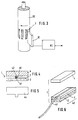
- a honing stone 1 (FIG. 1) is formed by a cutting surface 2, an adhesive layer 3 and a steel sole 4.
- the steel sole is usually approx. 1-3 mm thick, the adhesive layer usually 0.1 to 0.2 mm. It consists of binding material and various non-ferrous metals (e.g. copper, zinc, tin).
- the cutting surface consists of binding material with embedded diamond grain, with a diameter of 7 - 400 ⁇ m and a concentration of 1 to 200 carats / cm3. Such honing stones are sintered at temperatures of 700 - 1000 °.
- a fluorescent dye represented in the form of powder particles 5, is embedded in the adhesive layer 3 in the ratio of two parts of binding powder to one part of dye.
- Fluorescent dyes that can withstand high temperatures and are not toxic are known from the cosmetics and printing industries. They are obtained using so-called fluorophores.
- Figure 2 shows a measuring device for measuring the wear of a honing stone 1. Is the cutting surface 2 worn out so far. that the adhesive layer 4 containing the fluorescent dye comes to light, this can then be determined:
- a measuring device 10 is provided on the relevant machine tool (honing machine, grinding machine). It has a selectively emitting radiation arrangement, formed by a radiation source 11, filter 12 and a lens arrangement 13 for focusing the emitted radiation.
- the bundled radiation strikes the honing stone 1, ie - after the cutting coating 2 has worn - the adhesive layer 3 containing the fluorescent substance 5.
- a receiver arrangement is also provided, consisting of a lens arrangement 14, filters 15 and corresponding photodiodes 16.
- the photodiodes 16 are a detector, ie a component, the electrical signal of which is determined by the incident radiation.
- the transmitter arrangement and the receiver arrangement are such that the radiation which is emitted by the substance 5 when it is excited by the transmitter arrangement, is received by the receiver arrangement. Only one filter 12 or 15 is shown in the figures. This is done for the sake of clarity of presentation. In order to determine the individual wavelengths of the specific spectra, several filters 12 or 15 with associated lenses can be provided in a coordinated manner.
- the filters 12 are so determined that a specific wavelength distribution (spectrum) remains from the radiation source 11, which reaches the surface of the tool 1.
- This radiation is called excitation radiation, e.g. with wavelengths of 254 and 366 nm.
- excitation radiation e.g. with wavelengths of 254 and 366 nm.
- emission radiation e.g. with wavelengths of 490, 530, 610 nm.
- the excitation radiation of a specific spectrum can either be generated in that the radiation source 11 itself already emits a correspondingly selective spectrum (for example a low-pressure mercury lamp).
- a correspondingly selective spectrum for example a low-pressure mercury lamp.
- appropriate filters between the radiation source and the surface to be excited by the excitation radiation 12 introduces, the permeability is selected accordingly.
- the filters 15 are tuned in such a way that they only pass radiation of the corresponding emission spectrum. This ensures absolutely that only the radiation caused by the fluorescence of the fluorescent dye in the adhesive layer 3 reaches the photodiode 16 and leads there to a corresponding electrical signal.
- Such an arrangement is insensitive to any other type of radiation (scattered light from other radiation sources; undesired reflections, etc.).
- a further receiver is provided in the form of a photodiode 21, which directly receives the radiation emitted by the radiation source 11.
- the signals from both photodiode arrays 16 and 21 reach a quotient generator 22. It provides the ratio of the two signals. This ensures that fluctuations in the lighting intensity (for example caused by fluctuations in the power supply (not shown)) are not included in the final signal on line 23 emitted by the quotient generator 22.
- the signal at the output of the quotient generator 22 is sent to a personal computer PC for evaluation and / or registration. Via further lines 24, 24 '. 24 ⁇ there are signals such as "advance warning", "earliest time to change", "latest time to change".
- FIG. 3 shows the arrangement of the measuring device 10 in the vicinity of a honing tool 30, along the circumference of which a plurality of honing stones 1 are arranged.
- the fluorescent dye in the form of powder particles 5 is mixed into the adhesive layer 3, which becomes apparent as soon as the cutting bellows 2 is worn out.
- FIG. 4 Another design of the honing stone is shown in FIG. 4.
- the adhesive layer 3 is provided with a groove 40. This is cut so deep that it just protrudes into the surface of the cutting surface 2 or adjoins it in such a way that the groove is exposed from the outside after wear of the cutting surface 2.
- the groove itself has e.g. a cross section of 0.3 x 0.3 mm.
- a copper wire 41 is inserted into this groove as an indicator carrier; it has a coating 42 made of fluorescent dye as an indicator.
- the coating can be about 0.1 mm thick.
- a molded part 43 consisting of adhesive layer 3 and cutting bellows 2 is produced, into which a groove 40 is then made using a stamp 44 shown in cross section in FIG. 5.
- the copper wire 41 is then laid in this groove.
- the steel sole 4 is pressed on and the entire honing stone 1 is sintered.
- a groove 50 is introduced into the tool (for example by spark erosion) in such a way that the foot of the groove just just projects into or closes with the cutting surface 2 and, if the cutting surface 2 wears, the groove 50 from this side is exposed. becomes.
- Fluorescent dye 5 is then introduced into the groove.
- the groove is then closed with solder 51.
- a hole can also be made instead of a groove. It generally has to be a depression that extends to the cutting surface.
- the measuring device 10 is a photometric arrangement, including the selectively absorbing and / or emitting substance, in the tool by means of a transmitter / receiver arrangement.
- the fluorometric method shown it is also possible to determine absorption of infrared radiation or UV radiation. With all types of radiation, it is particularly favorable if it is not visible light in order to eliminate the effects of stray light or extraneous light.
Landscapes
- Engineering & Computer Science (AREA)
- Mechanical Engineering (AREA)
- Finish Polishing, Edge Sharpening, And Grinding By Specific Grinding Devices (AREA)
- Constituent Portions Of Griding Lathes, Driving, Sensing And Control (AREA)
- Machine Tool Sensing Apparatuses (AREA)
- Length Measuring Devices By Optical Means (AREA)
Description
Die Erfindung betrifft ein Honwerkzeug oder eine Schleifscheibe, gebildet durch einen Schneidkörper und einen den Schneidkörper tragenden Schneidkörperträger und eine Meßeinrichtung zur Messung des Verschleißes derartiger Werkzeuge.The invention relates to a honing tool or a grinding wheel, formed by a cutting body and a cutting body carrier carrying the cutting body and a measuring device for measuring the wear of such tools.
Derartige Werkzeuge sind bekannt. Es handelt sich dabei um Werkzeuge zur spanabhebenden Bearbeitung, bei denen ein Schneidbelag (=Schneidkörper) mittels einer Haftschicht auf einer Stahlsohle (=Schneidkörperträger) angeordnet ist.Such tools are known. These are tools for machining, in which a cutting surface (= cutting body) is arranged on a steel base (= cutting body support) by means of an adhesive layer.
Im Zuge der Einrichtung vollautomatischer Bearbeitungsabläufe, meist bei mehrspindligen Maschinen, ist die Verschleißüberwachung für die Betriebssicherheit und die Fertigungsqualität von großer Bedeutung. Der Verschleiß einer Honleiste ist weitgehend abhängig von der Zahl der bearbeiteten Werkstücke (Standmenge). Andere Einflüsse sind z.B. der Vorschub, die Werkstoffhärte oder Inhomogenitäten des Werkzeuges. Für die wirtschaftliche Fertigung ist der Werkzeugwechsel zur rechten Zeit sehr wichtig. Er darf weder zu früh erfolgen, d.h., wenn das Schneidmittelvolumen (Volumen des Schneidkörpers oder Schneidbelags) noch nicht vollständig ausgenutzt ist; er darf auch nicht zu spät erfolgen, denn dies würde eine Produktion mit nicht mehr qualitativ vollwertigen Werkzeugen bedeuten und somit zu Ausschuß führen.In the course of setting up fully automatic machining processes, usually in multi-spindle machines, wear monitoring is of great importance for operational safety and manufacturing quality. The wear of a honing stone largely depends on the number of machined workpieces (tool life). Other influences are e.g. the feed, the material hardness or inhomogeneities of the tool. Tool change at the right time is very important for economical production. It must not be done too early, i.e. if the volume of the cutting material (volume of the cutting body or cutting surface) has not yet been fully used; it must also not be done too late, because this would mean production with tools that are no longer of high quality and thus lead to rejects.
Bisher konnte man die Überwachung des Verschleißes des Schneidkörpers einer Honleiste oder einer Schleifscheibe z.B. angenähert dadurch lösen, daß - im einfachsten Fall - für die jeweilige Bearbeitungsoperation die kleinste Standmenge (Zahl der bearbeiteten Werkstücke) ermittelt und dieser Wert als Richtwert einer in entsprechenden Abständen erfolgenden Überprüfung der Werkzeugmaschine durch das Bedienungspersonal zugrunde gelegt wurde. Die Überprüfung selbst erfolgte durch Betrachtung des Werkzeuges.Up to now it was possible to monitor the wear of the cutting body of a honing stone or a grinding wheel e.g. Approximately solve this in that - in the simplest case - the smallest tool life (number of machined workpieces) is determined for the respective machining operation and this value was used as a guideline for an inspection of the machine tool by the operating personnel at appropriate intervals. The check itself was carried out by looking at the tool.
Eine andere Möglichkeit besteht in der Überwachung des Zustellweges bei elektronisch-mechanischer oder elektronisch-hydraulischer Zustellung der Werkzeuge. Dies bedeutet jedoch nur eine indirekte Kontrolle des Verschleißes des Schneidbelages einer Honleiste. Erfolgt die Zustellung in Schritten durch eine bestimmte Zahl von Impulsen, so kann man - entsprechend der vermuteten Abnutzung - nach einer voreinstellbaren Anzahl von Bearbeitungszyklen eine ebenfalls fest voreinstellbare Anzahl zusätzlicher Zustellimpulse vorsehen. Auch eine solche Einrichtung stellt jedoch keine tatsächliche Verschleißüberwachung, sondern ausschließlich eine Verschleißkompensation. Erst die Summe der zur Kompensation erforderlichen zusätzlichen Impulse und der Vergleich mit einer empirisch vorgegebenen nutzbaren Höhe des Schneidbelags einer Honleiste ergibt jedoch die von einer Maschinensteuerung verwertbare Information, ob ein Auswechseln einer Honleiste erforderlich ist. Bei modernen Maschinensteuerungen werden die nutzbare Höhe des Schneidbelages, die Anzahl der Schritte je Kompensationsvorgang, und der Konuswinkel eines Honwerkzeuges der Steuerung eingegeben. Durch Aufsummieren der Kompensationswege wird bei Erreichen der Verschleißgrenze die Maschine stillgesetzt. Über Balkendiagramme am Bildschirm wird der Verschleißzustand der Honleisten dargestellt. Bei einer programmierbaren Warngrenze fordert die Maschinensteuerung das Bedienerpersonal rechtzeitig zum Werkzeugwechsel auf. Diese Werkzeugverschleißüberwachung ist jedoch nur einsetzbar, bei einer mittels Schrittmotor betriebenen Zustellung. Bei einer hydraulischen Zustellung läßt sich diese indirekte. Verschleißüberwachung nicht anwenden. Diese indirekte Überwachung hat ferner den Nachteil, daß sie die Fertigungstoleranzen in der Höhe berücksichtigen muß. Eine solche Höhe entspricht aber unter Umständen einer Standmenge von bis zu mehreren tausend Werkstücken. Die indirekte Verschleißüberwachung gewährleistet daher nicht eine möglichst wirtschaftliche Ausnutzung des Schneidbelages.Another possibility is to monitor the delivery route with electronic mechanical or electronic-hydraulic tool delivery. However, this only means an indirect control of the wear on the cutting surface of a honing stone. If the infeed is carried out in steps by a certain number of impulses, then a number of additional impulse, which can also be preset, can be provided after a presettable number of machining cycles, depending on the assumed wear. However, even such a device does not provide actual wear monitoring, but only wear compensation. It is only the sum of the additional pulses required for compensation and the comparison with an empirically predetermined usable height of the cutting surface of a honing stone, however, which gives the information which can be used by a machine control system as to whether a honing stone has to be replaced. With modern machine controls, the usable height of the cutting surface, the number of steps per compensation process, and the cone angle of a honing tool of the control are entered. By adding up the compensation paths, the machine is stopped when the wear limit is reached. The wear status of the honing stones is shown via bar graphs on the screen. If the warning limit is programmable, the machine control prompts the operator to change the tool in good time. However, this tool wear monitoring can only be used with a feed operated by means of a stepper motor. In the case of hydraulic infeed, this can be done indirectly. Do not use wear monitoring. This indirect monitoring also has the disadvantage that it must take into account the manufacturing tolerances in height. Such a height may correspond to a tool life of up to several thousand workpieces. Indirect wear monitoring therefore does not guarantee the most economical use of the cutting surface.
Es sind keine Honleisten bekannt, bei denen der Verschleißzustand direkt erfaßt werden kann. Aus benachbarten Gebieten sind zwar Werkzeuge zur spanabhebenden Bearbeitung von Werkstücken bekannt, bei denen eine Verschleißüberwachung erfolgt. Die dabei verwandten Technologien können jedoch nicht unmittelbar dazu eingesetzt werden. eine Honleiste zu schaffen, bei der die Verschleißüberwachung direkt erfolgen kann.No honing stones are known in which the state of wear can be recorded directly. Tools for machining workpieces, in which wear monitoring is carried out, are known from neighboring areas. However, the technologies used here cannot be used directly. to create a honing stone in which wear monitoring can be carried out directly.
In der EP-A-0 225 300 wird z.B. eine Wendeschneidplatte beschrieben, bei welcher auf einem Substrat, das Strahlung emittiert, eine strahlungsundurchlässige Schicht aufgebracht ist. Bei zunehmendem Verschleiß wird im Bereich der Freifläche das Strahlung emittierende Substrat zunehmend freigelegt. Die von dem Substrat emittierte Strahlung wird als Maß der Abnutzung festgestellt. Außerdem ist es aus dieser Druckschrift bekannt, kleinflächige Abnutzungen vom Typ Kraterverschleiß an der Schneide selbst festzustellen. Die direkte Verschleißüberwachung über den Freiflächenverschleiß ist bei Honleisten nicht anwendbar, da diese ja insgesamt mit dem Werkstück in großflächigem Kontakt stehen und keine Freiflächen aufweisen, an denen in dieser Weise der Verschleiß festgestellt werden könnte.EP-A-0 225 300, for example, describes an indexable insert in which a radiation-opaque layer is applied to a substrate that emits radiation. With increasing wear, the radiation-emitting substrate is increasingly exposed in the area of the open area. The radiation emitted by the substrate is determined as a measure of the wear. In addition, it is known from this document to determine small-area wear of the crater wear type on the cutting edge itself. Direct wear monitoring via free-space wear is not applicable to honing stones, since they are in total contact with the workpiece and have no free areas on which wear could be determined in this way.
Ähnliches gilt für die DD-A-222 414. Daraus ist ein Verfahren zur Verschleißerkennung an einem Drehstahl bekannt, bei dem eine punktförmige, radioaktive Markierung auf der Freifläche und/oder der Spanfläche des Werkzeugs aufgebracht wird. Bei Verschleiß wird die radioaktive Markierung mit abgetragen. Die dadurch bewirkte Änderung der Strahlung dient zur Messung des Verschleißes. Eine derartige Verschleißmessung ist außer wegen der nicht unkritischen Strahlenbelastung des Arbeitsplatzes bei Honleisten deshalb nicht anwendbar, weil eine flächige Überwachung des Schneidkörpers nicht möglich ist.The same applies to DD-A-222 414. From this, a method for wear detection on a turning tool is known, in which a punctiform radioactive marking is applied to the free surface and / or the rake surface of the tool. In the event of wear, the radioactive marking is also removed. The resulting change in radiation is used to measure wear. Such a wear measurement is not applicable to honing stones, because of the not uncritical radiation exposure of the workplace, because a flat monitoring of the cutting body is not possible.
Aus der DE-Z Fertigungstechnik und Betrieb (1985) 9, Seite 523-526, insbesonders S. 524, ist es bekannt, die Freifläche einer Wendeschneidplatte mit einer radioaktiven Markierung zu überziehen. Die Verschleißerkennung erfolgt wiederum durch die Messung des Freiflächenverschleißes. Auch dieses Verfahren ist, neben dem Nachteil der Strahlenbelastung, bei Honleisten deshalb nicht anwendbar, weil diese keine Freiflächen haben. Dasselbe gilt für das alternativ in dieser Veröffentlichung genannte Meßprinzip der Anbringung von Leitbahnstrukturen an den Freiflächen, die bei Masseverbindung infolge Verschleiß ein Signal abgeben. Hon- oder Schleifwerkzeuge sind beides Werkzeuge mit unbestimmter Schneidengeometrie bei denen - im Gegensatz zu Wendeplatten, Bohrern oder Drehstählen - Freiflächen generell nicht existieren.It is known from DE-Z Manufacturing Technology and Operation (1985) 9, pages 523-526, in particular p. 524, to coat the open area of an indexable insert with a radioactive marking. Wear detection is in turn carried out by measuring the wear of the open area. In addition to the disadvantage of radiation exposure, this method is also not applicable to honing stones because they have no free areas. The same applies to the measuring principle of attaching interconnect structures to the open areas, which is alternatively mentioned in this publication and which emits a signal when grounded due to wear. Honing or grinding tools are both Tools with an undefined cutting edge geometry which - unlike indexable inserts, drills or turning tools - generally do not have free surfaces.
Aus der US-PS 4,420,253 ist ein Bohrer bekannt, in dessen Schaft eine Glasfaser eingelassen ist. Das eine Ende der Glasfaser wird von einer Lichtquelle bestrahlt. Das andere Ende erstreckt sich in den Schaft hinein und endet in einem bestimmten Abstand von der Schneide. Nach Abtrag dieses zwischen Faserende und Schneide liegenden Materials wird das Licht in einem unterhalb des Bohrers angeordneten Detektor registriert. Mit einem solchen Verfahren ist die Verschleißüberwachung einer Honleiste nicht möglich, da die gesamte Fläche des Schneidkörpers so nicht ohne extremen Aufwand überwacht werden könnte.A drill is known from US Pat. No. 4,420,253, in the shaft of which a glass fiber is embedded. One end of the glass fiber is illuminated by a light source. The other end extends into the shaft and ends at a certain distance from the cutting edge. After removal of this material lying between the fiber end and the cutting edge, the light is registered in a detector arranged below the drill. With such a method, wear monitoring of a honing stone is not possible, since the entire surface of the cutting body could not be monitored without extreme effort.
Aus der DE-OS 34 04 257 ist eine Meßeinrichtung zur Messung der Abnutzung eines Messers zum Schneiden von Halbleiterscheiben bekannt. Bei dieser wird der von einer Senderanordnung ausgehende und vom Messer reflektierte Lichtstrahl in einem Detektor registriert. Der Verschleiß des Messerkörpers bringt eine Änderung des Reflektionsverhaltens des Messers mit sich. Dadurch verändert sich auch die Intensität des reflektierten Lichtstrahl. Diese Meßeinrichtung hat den Nachteil, daß sie gegenüber Streulicht anderer Strahlungsquellen sehr empfindlich ist. Wie in dieser Durchschrift ausgeführt, funktioniert die Meßeinrichtung nicht, wenn das Messer durch Spül- und/oder Kühlmedien benetzt ist. Die Meßeinrichtung liefert ferner nur ein Signal, welches - bedingt durch die Rotation des Messers - einem über einen Teilbereich des Messers gemittelten Verschleiß entspricht.From DE-OS 34 04 257 a measuring device for measuring the wear of a knife for cutting semiconductor wafers is known. In this the light beam emanating from a transmitter arrangement and reflected by the knife is registered in a detector. The wear of the knife body changes the reflective behavior of the knife. This also changes the intensity of the reflected light beam. This measuring device has the disadvantage that it is very sensitive to scattered light from other radiation sources. As stated in this transcript, the measuring device works not if the knife is wetted by rinsing and / or cooling media. The measuring device also only delivers a signal which - due to the rotation of the knife - corresponds to wear averaged over a partial area of the knife.
Für Honwerkzeuge der Schleifscheiben wäre ein derartiges Verfahren. selbst wenn man die genannten Nachteile in Kauf nehmen wollte, schon vom Prinzip her nicht anwendbar, weil sich der Verschleiß dieser Werkzeuge in dem ansonsten relativ genau bestimmbaren Zeitpunkt, in dem sie ausgewechselt werden müssen, nicht eindeutig dem Reflektionsverhalten der Oberfläche des Schneidkörpers zuordnen läßt.Such a method would be for honing tools on the grinding wheels. even if one wanted to accept the disadvantages mentioned, in principle not applicable, because the wear of these tools cannot be clearly assigned to the reflective behavior of the surface of the cutting body in the otherwise relatively precisely determinable time in which they have to be replaced.
In der US-A-40 31 368 ist eine Meßeinrichtung an einer Werkzeugmaschine beschrieben, bei der ein Laserstrahl über das Werkzeug geführt wird. Die Reflektion des Laserstrahls wird in einer Empfängeranordnung registriert und an eine Auswerteeinrichtung weitergeleitet. Diese Auswerteeinrichtung berechnet aus den optischen Meßdaten in Verbindung mit anderen Parametern (z.B. Werkstückabmessungen, Vibrationen, Oberflächenrauhigkeit u.a.) den Verschleiß. Diese Meßvorrichtung setzt kostspielige und wartungsintensive Einrichtungen, so u.a. einen Laserresonator voraus, Die Anwendbarkeit auf die Feststellung des Verschleißes von Honleisten entfällt aus den bereits oben angegebenen Gründen.US-A-40 31 368 describes a measuring device on a machine tool in which a laser beam is guided over the tool. The reflection of the laser beam is registered in a receiver arrangement and forwarded to an evaluation device. This evaluation device calculates the wear from the optical measurement data in connection with other parameters (e.g. workpiece dimensions, vibrations, surface roughness etc.). This measuring device uses costly and maintenance-intensive devices, e.g. a laser resonator in advance, the applicability to the determination of wear of honing stones does not apply for the reasons given above.
Es ist Aufgabe der Erfindung, ein Honwerkzeug und eine Schleifscheibe der eingangs genannten Art derart weiterzubilden, daß es möglich wird, den Verschleißzustand des Schneidkörpers direkt zu erfassen, d.h. festzustellen, wann der Schneidkörper abgenutzt ist, so daß ein Auswechseln der Honleiste erforderlich ist. Als "Schneidkörper" wird dabei der durch Bindematerial mit Diamantkorn gebildete Schneidbelag einer Honleiste oder Schleifscheibe verstanden. Die Honleiste soll ferner derart ausgebildet sein, daß die Überwachung von Ungenauigkeiten des Schneidbelags unabhängig ist, d.h. es soll möglich sein, trotz derartiger Ungenauigkeiten in der Höhe des Schneidbelags genau den richtigen Zeitpunkt zum Werkzeugwechsel festzustellen. Die Verschleißmessung an der Honleiste mittels der beschriebenen Meßvorrichtung soll auch dann noch funktionieren, wenn die Honleiste durch Spül- oder Kühlmedien (z.B. Honöl) benetzt ist. Ferner soll eine geeignete Meßeinrichtung zur Messung des Verschleißes eines derartigen Hon- oder Schleifwerkzeuges bereitgestellt werden, mit der der Verschleißzustand einfach und direkt erfaßt werden kann, d.h. festgestellt werden kann, wann der Schneidkörper abgenutzt und ein Auswechseln erforderlich ist.It is an object of the invention to develop a honing tool and a grinding wheel of the type mentioned at the outset in such a way that it it is possible to directly record the state of wear of the cutting body, ie to determine when the cutting body is worn, so that the honing stone has to be replaced. The "cutting body" is understood to mean the cutting surface of a honing stone or grinding wheel formed by binding material with diamond grain. The honing stone should also be designed in such a way that the monitoring of inaccuracies in the cutting surface is independent, ie it should be possible to determine exactly the right time for changing the tool despite such inaccuracies in the height of the cutting surface. The wear measurement on the honing stone by means of the measuring device described should still work even if the honing stone is wetted by flushing or cooling media (eg honing oil). Furthermore, a suitable measuring device for measuring the wear of such a honing or grinding tool is to be provided, with which the state of wear can be detected simply and directly, ie it can be determined when the cutting body is worn and a replacement is necessary.
Diese Aufgabe wird erfindungsgemäß durch ein Honwerkzeug oder eine Schleifscheibe der eingangs genannten Art gelöst, bei dem zwischen Schneidkörper und Schneidkörperträger eine elektromagnetische Strahlung bei einer spezifischen Wellenlänge selektiv absorbierende und/oder eine bei Anregung elektromagnetische Strahlung selektiv emittierende Substanz als Schicht, in eine Schicht aus anderem Material eingebettet, oder als Beschichtung eines als diskretes Element unter dem Schneidkörper angeordneten Indikatorträger angeordnet ist.This object is achieved according to the invention by a honing tool or a grinding wheel of the type mentioned at the outset, in which an electromagnetic radiation at a specific wavelength is selectively absorbed between the cutting body and the cutting body carrier and / or a substance is selectively emitted as a layer upon excitation of electromagnetic radiation, into a layer of another Embedded material, or as a coating of an indicator carrier arranged as a discrete element under the cutting body.
Eine Meßeinrichtung zur Messung des Verschleißes eines Hon-oder Schleifwerkzeuges der genannten Art ist dadurch gekennzeichnet, daß eine selektiv Lichtstrahlung abgebende Sendeanorndung auf den Schneidkörper ausgerichtet angeordnet ist, und daß ferner eine selektive Strahlung aufnehmende Empfängeranordnung derart auf das Honwerkzeug ausgerichtet angeordnet ist, daß sie die von der Sendeanordnung auf das Werkzeug abgestrahlte und vom Werkzeug reflektierte Strahlung aufnimmt und aus dieser ein Anzeigesignal ableitet.A measuring device for measuring the wear of a honing or grinding tool of the type mentioned is characterized in that a transmitting arrangement which emits selective light radiation is arranged in alignment with the cutting body, and in that a selective radiation-receiving receiver arrangement is arranged in such a way that it aligns the honing tool receives radiation emitted by the transmitter arrangement on the tool and reflected by the tool and derives an indication signal from the latter.
Vorteilhafte Weiterbildungen der Erfindungen sind in den Unteransprüchen definiert.Advantageous developments of the inventions are defined in the subclaims.
Die Aufgabe wird erfindungsgemäß durch die im Kennzeichen des Patentanspruches 1 angegebenen Merkmale gelöst.The object is achieved by the features specified in the characterizing part of patent claim 1.
Sobald der "Schneidkörper", d.h. der Schneidbelag der Honleiste abgenutzt ist, tritt die darunter angeordnete, eine Anregungsstrahlung selektiv absorbierende oder bei Anregung selektiv emittierende Substanz zutage. Dies kann ohne komplizierte Auswertung der Strahlung erfaßt und somit dem Ausmaß des Verschleißes, der einen Werkzeugwechsel notwendig macht, zugeordnet und daraus ein Signal abgeleitet werden, das entweder das Bedienungspersonal informiert oder aber einen automatischen Werkzeugwechsel initiiert. Die Meßvorrichtung besitzt ferner den Vorteil, daß die Messung gegenüber Streulicht anderer Strahlungsquellen, unerwünschte Reflektionen, auch von der Schneidkörperoberfläche, usw. unempfindlich ist. Es können somit Abschirmvorrichtungen entfallen. Die Messung kann direkt am Werkzeug unter normalen Bearbeitungsbedingungen durchgeführt werden. Der Meßvorgang funktioniert auch, wenn die Honleiste oder Schleifscheibe durch Spül- und/oder Kühlmedien benetzt ist.As soon as the "cutting body", ie the cutting surface of the honing stone is worn, the substance arranged below it, selectively absorbing excitation radiation or selectively emitting upon excitation, comes to light. This can be detected without a complicated evaluation of the radiation and can thus be assigned to the extent of wear that necessitates a tool change and a signal can be derived therefrom which either informs the operating personnel or one automatic tool change initiated. The measuring device also has the advantage that the measurement is insensitive to scattered light from other radiation sources, unwanted reflections, also from the cutting surface, etc. Shielding devices can thus be omitted. The measurement can be carried out directly on the tool under normal machining conditions. The measuring process also works when the honing stone or grinding wheel is wetted by rinsing and / or cooling media.
Ausführungsbeispiele der Erfindung und ihrer vorteilhaften Weiterbildungen werden im folgenden anhand der beigefügten Zeichnungen beschrieben. Es stellen dar:
- Figur 1
- ein Querschnitt durch ein Ausführungsbeispiel eines Werkzeuges;
Figur 2- ein Ausführungsbeispiel einer Meßvorrichtung;
Figur 3- die Anordnung der Meßvorrichtung nach Fig. 3 an einem Honwerkzeug;
- Figur 4
- den Querschnitt durch ein zweites Ausführungsbeispiel eines Werkzeuges;
Figur 5- den Querschnitt eines Stempels zur Herstellung eines Werkzeuges nach Fig. 4;
- Figur 6
- einen Schritt in der Herstellung eines weiteren Ausführungsbeispiels eines erfindungsgemäßen Werkzeuges;
- Figur 7
- den Querschnitt durch ein weiteres Ausführungsbeispiel eines Werkzeuges;
- Figur 8
- eine Draufsicht auf das Werkzeug nach Fig. 7.
- Figure 1
- a cross section through an embodiment of a tool;
- Figure 2
- an embodiment of a measuring device;
- Figure 3
- the arrangement of the measuring device of Figure 3 on a honing tool.
- Figure 4
- the cross section through a second embodiment of a tool;
- Figure 5
- the cross section of a stamp for producing a tool according to Fig. 4;
- Figure 6
- a step in the production of a further embodiment of a tool according to the invention;
- Figure 7
- the cross section through a further embodiment of a tool;
- Figure 8
- 7 shows a plan view of the tool according to FIG. 7.
Eine Honleiste 1 (Fig. 1) wird durch einen Schneidbelag 2, eine Haftschicht 3 und eine Stahlsohle 4 gebildet. Die Stahlsohle ist üblicherweise ca. 1-3 mm stark, die Haftschicht üblicherweise 0,1 bis 0,2 mm. Sie besteht aus Bindematerial sowie aus verschiedenen Buntmetallen (z.B. Kupfer, Zink, Zinn). Der Schneidbelag besteht aus Bindematerial mit eingelagertem Diamantkorn, mit einem Durchmesser von 7 - 400 um und einer Konzentration von 1 bis 200 Karat/cm³. Derartige Honleisten werden bei Temperaturen von 700 - 1000° gesintert.A honing stone 1 (FIG. 1) is formed by a cutting
Im Ausführungsbeispiel nach Fig. 1 ist in die Haftschicht 3 ein flureszierender Farbstoff, dargestellt in Form von Pulverteilchen 5 im Verhältnis zwei Teile Bindungspulver zu einem Teil Farbstoff, eingebettet. Fluoreszierende Farbstoffe, die hohe Temperaturen aushalten und nicht giftig sind, sind aus der Kosmetik und der Druckindustrie bekannt. Sie werden mittels sog. Fluorophore gewonnen.In the exemplary embodiment according to FIG. 1, a fluorescent dye, represented in the form of
Figur 2 zeigt eine Meßvorrichtung zur Messung des Verschleißes einer Honleiste 1. Ist der Schneidbelag 2 soweit abgenützt. daß die den fluoreszierenden Farbstoff enthaltende Haftschicht 4 zutage tritt, sodann kann dies festgestellt werden:Figure 2 shows a measuring device for measuring the wear of a honing stone 1. Is the cutting
Zu diesem Zweck ist an der betreffenden Werkzeugmaschine (Honmaschine, Schleifmaschine) eine Meßeinrichtung 10 vorgesehen. Sie weist eine selektiv Strahlung abgebende Sendeanordnung auf, bebildet durch eine Strahlungsquelle 11, Filter 12 und eine Linsenanordnung 13 zur Bündelung der abgegebenen Strahlung auf. Die gebündelte Strahlung trifft auf die Honleiste 1, d.h. - nach Verschleiß des Schneidbelages 2 - auf die den die fluoreszierenden Substanz 5 enthaltende Haftschicht 3. Es ist ferner eine Empfängeranordnung vorgesehen, bestehend aus einer Linsenanordnung 14, Filteren 15 und entsprechenden Fotodioden 16. Die Fotodioden 16 sind ein Detektor, d.h. ein Bauteil, dessen elektrisches Signal durch die auftreffende Strahlung bestimmt wird. Die Senderanordnung und die Empfängeranordnung sind derart, daß die Strahlung, die von der Substanz 5 emittiert wird, wenn sie durch die Senderanordnung angeregt wird, von der Empfängeranordnung aufgenommen wird. In den Figuren ist jeweils nur ein Filter 12 bzw. 15 gezeigt. Dies geschieht der Übersichtlichkeit der Darstellung halber. Um die einzelnen Wellenlängen der spezifischen Spektren zu ermitteln, können jewils abgestimmt mehrere Filter 12 bzw. 15 mit zugeordneten Linsen vorgesehen sein.For this purpose, a measuring
Die Filter 12 sind so bestimmt, daß von der Strahlungsquelle 11 eine spezifische Wellenlängenverteilung (Spektrum) verbleibt, welche an die Oberfläche des Werkzeugs 1 gelangt. Diese Strahlung bezeichnet man als Anregungsstrahlung, z.B. mit Wellenlängen von 254 und 366 nm. Sie ruft beim Auftreffen auf die in der Haftschicht 3 in Form von Pulverteilchen 5 inkorporierte flureszierende Substanz eine Emmisionsstrahlung hervor, welche eine andere spezifische Wellenlängenverteilung (Spektrum) aufweist, z.B. mit Wellenlängen von 490, 530, 610 nm.The
Die Anregungsstrahlung eines bestimmten Spektrums kann run entweder dadurch erzeugt werden, daß die Strahlungsquelle 11 selbst bereits bereits ein entsprechend selektives Spektrum abgibt (z.B. ein Quecksilber-Niederdruckstrahler). Eine andere Möglichkeit, wie in Fig. 2 dargestellt, besteht darin, daß man zwischen die Strahlungsquelle und die durch die Anregungsstrahlung anzuregende Oberfläche entsprechende Filter 12 einbringt, deren Durchlässigkeit entsprechend selektiv abgestimmt ist. Entsprechend sind die Filter 15 so abgestimmt, daß sie nur Strahlung des entsprechenden Emissionsspektrums durchläßt. Damit ist absolut sichergestellt, daß nur die durch Fluoreszenz des fluoreszierenden Farbstoffes in der Haftschicht 3 hervorgerufene Strahlung an die Fotodiode 16 gelangt und dort zu einem entsprechenden elektrischen Signal führt. Gegenüber irgendwelchen sonsitgen Strahlungen (Streulicht anderer Strahlungsquellen; unerwünschte Reflektionen, usw.) ist einen derartige Anordnung unempfindlich.The excitation radiation of a specific spectrum can either be generated in that the
Parallel zu der dergestellten Sender/Empfänger-Anordnung ist noch in Gestalt einer Fotodiode 21 ein weiterer Empfänger vorgesehen, der direkt die von der Strahlungsquelle 11 abgestrahlte Strahlung aufnimmt. Die Signale von beiden Fotodiodenanordnungen 16 und 21 gelangen an einen Quotientenbildner 22. Er liefert das Verhältnis beider Signale. Damit wird gewährleistet, daß Schwankungen der Beleuchtungsintensität (z.B. verursacht durch Schwankungen der (nicht gezeigten) Stromversorgung) in das endgültige vom Quotientenbildner 22 abgegebene Signal auf Leitung 23 nicht mit eingehen. Das Signal am Ausgang des Quotientenbildners 22 gelangt an einen Personal Computer PC zur Auswertung und/oder Registrierung. Über weitere Leitungen 24,24′. 24˝ erfolgen z.B. Signale "Vorwarnung", "frühester Zeitpunkt zum Wechseln", "spätester Zeitpunkt zum Wechseln".In parallel to the transmitter / receiver arrangement shown, a further receiver is provided in the form of a
Figur 3 zeigt die Anordnung der Meßeinrichtung 10 in Nähe eines Honwerkzeuges 30, entlang dessen Umfang mehrere Honleisten 1 angeordnet sind.FIG. 3 shows the arrangement of the measuring
In Fig. 1 wird der fluoreszierende Farbstoff in Form von Pulverteilchen 5 in die Haftschicht 3 gemischt, die zutage tritt, sobald der Schneidbalag 2 verschlissen ist. Eine andere Ausbildung der Honleiste zeigt Fig. 4. Dort wird - vor Aufbringen der Stahlsohle 4 - die Haftschicht 3 mit einer Nut 40 versehen. Diese ist so tief geschnitten, daß sie gerade in die Oberfläche des Schneidbelages 2 hineinragt oder an sie angrenzt, derart, daß nach Verschleiß des Schneidbelages 2 die Nut von außen her freiliegt. Die Nut selbst hat z.B. einen Querschnitt von 0,3 x 0,3 mm. In diese Nut wird ein Kupferdraht 41 als Indikatorträger eingelegt; er trägt als Indikator eine Beschichtung 42 aus fluoreszierendem Farbstoff. Die Beschichtung kann ca. 0,1 mm dick sein. Zunächst wird (vgl. Fig. 6), ein aus Haftschicht 3 und Schneidbalag 2 bestehender Formteil 43 hergestellt wird, in den dann mit Hilfe eines im Querschnitt in Fig. 5 dargestellten Stempels 44 eine Nut 40 eingeschlagen wird. In diese Nut wird dann der Kupferdraht 41 verlegt. Anschließend die Stahlsohle 4 aufgepresst und die gesamte Honleiste 1 gesintert. Vorteilhaft an dieser Anordnung im Vergleich zu Fig. 1 ist, daß keine Schwächung des Querschittes der Haftschicht erfolgt.In Fig. 1, the fluorescent dye in the form of
Nach Figur 7 und 8 wird nach dem Fertigstellen der gesamten Honleiste 1 von der Seite der Stahsohle 4 her eine Nut 50 in das Werkzeug eingebracht (z.B. durch Funkenerosion) derart, daß der Fuß der Nut gerade eben in den Schneidbelag 2 hineinragt bzw. mit diesem abschließt und bei Verschleiß des Schneidbelages 2 die Nut 50 von dieser Seite her freigliegt. wird. In die Nut ist dann fluoreszierender Farbstoff 5 eingebracht. Die Nut ist dann mit Lot 51 verschlossen. Vorteilhaft ist dabei, daß der Farbstoff nicht der Temperatur und dem Druck eines Sintervorgangs ausgesetzt werden muß, weil er erst danach eingebracht wird. Anstelle einer Nut kann auch eine Bohrung eingebracht werden. Es muß eben allgemein eine Vertiefung sein, die bis zum Schneidbelag reicht.According to Figures 7 and 8, after the completion of the whole Honing stone 1 from the side of the steel soleplate 4, a groove 50 is introduced into the tool (for example by spark erosion) in such a way that the foot of the groove just just projects into or closes with the cutting
Wesentlich ist daß nach Verschleiß des Schneidkörpers eine Substanz zutage tritt, deren Zutagetreten selektiv festgestellt werden kann. Dies kann nicht nur durch die Messung einer selektiv emittierten Strahlung erfolgen, sondern auch durch die Messung selektiver Absorbtion. Generell handelt es sich bei der Meßeinrichtung 10 um eine fotometrische Anordnung unter Einbeziehung der selektiv absorbierenden und/oder emittierenden Substanz, im Werkzeug durch eine Sender/Empfänger-Anordnung. Alternativ zu der dargestellten fluorometrischen Methode ist auch die Feststellung einer Absorbtion von Infrarotstrahlung oder UV-Strahlung möglich. Bei allen Strahlungen ist es besonders günstig, wenn es sich nicht um sichtbares Licht handelt, um Streulicht- oder Fremdlicht-Einflüsse auszuschalten.It is essential that after wear of the cutting body a substance comes to light, the entry of which can be determined selectively. This can be done not only by measuring selectively emitted radiation, but also by measuring selective absorption. In general, the measuring
Auf allen diesen Wegen ist es möglich, eine einwandfrei funktionierende zur Selbstidentifikation verschlissener Werkzeuge (Honleisten, Schleifscheibe) geeignete Meßvorrichtung zu erhalten.In all of these ways, it is possible to obtain a perfectly functioning measuring device suitable for self-identification of worn tools (honing stones, grinding wheel).
Claims (9)
- A honing tool or grinding wheel formed by a cutting body (2) and a cutting body carrier (4) which carries the cutting body characterised in that disposed between the cutting body (2) and the cutting body carrier (4) is a substance (5) which selectively absorbs electromagnetic radiation at a specific wavelength and/or selectively emits electromagnetic radiation when stimulated, in the form of a layer, embedded into a layer of other material (3), or in the form of a coating (42) on an indicator carrier (41) which is arranged in the form of a discrete element under the cutting body (2) and which is arranged in a recess (40, 50) which is provided in a bonding layer (3) joining the cutting body (2) to the cutting body carrier (3) and/or the cutting body carrier, adjoining the cutting body carrier, in such a way that the substance (5) is exposed when the cutting body (2) is worn away.
- A honing tool or grinding wheel according to claim 1 characterised in that the indicator carrier (41) is a wire, preferably comprising a non-ferrous metal.
- A honing tool or grinding wheel according to claim 1 characterised in that the recess is formed by a groove (50) which is provided in the cutting body carrier (4) and the bonding layer (3) and which projects into the cutting coating (2) by which it is closed.
- A honing tool or grinding wheel according to claim 1 or one of the following claims characterised in that the cutting body is a cutting coating (2) which is applied by means of a bonding layer (3) to a steel base (4) forming the cutting body carrier.
- A honing tool or grinding wheel according to claim 1 or one of the following claims characterised in that the selectively emitting and/or absorbing substance is a fluorescent substance (5) which upon stimulation with a first given wavelength distribution emits a radiation with a second given wavelength distribution.
- A honing tool or grinding wheel according to one of claims 1 to 4 characterised in that the selectively absorbing or emitting substance is a UV-radiation-absorbing substance.
- A honing tool or grinding wheel according to one of claims 1 to 4 characterised in that the selectively absorbing or emitting substance is a substance which selectively absorbs infra-red radiation.
- A measuring device in conjunction with a honing tool or a grinding wheel according to claim 1 or one of the following claims characterised in that a transmitting arrangement (11, 12, 13) which selectively outputs light radiation is arranged to be directed on to the cutting body (2) and that in addition a receiver arrangement (14, 15, 16) which selectively receives radiation is arranged to be directed on to the honing tool (1) in such a way that it receives the radiation which is radiated from the transmitting arrangement on to the tool (1) and which is reflected by the tool and derives from said radiation a display signal (S1, S2, S3).
- A measuring device according to claim 8 characterised in that the electrical signal is applied to a differential amplifier (22) and that a signal which is derived directly from the transmitter arrangement (11) by means of a further receiver (21) is also applied to the differential amplifier (22) and that the output signal of the differential amplifier is the basis for evaluation in an evaluation unit (PC).
Applications Claiming Priority (2)
| Application Number | Priority Date | Filing Date | Title |
|---|---|---|---|
| DE3725652 | 1987-08-03 | ||
| DE3725652A DE3725652A1 (en) | 1987-08-03 | 1987-08-03 | CUTTING MACHINE TOOL |
Publications (3)
| Publication Number | Publication Date |
|---|---|
| EP0302565A2 EP0302565A2 (en) | 1989-02-08 |
| EP0302565A3 EP0302565A3 (en) | 1989-03-29 |
| EP0302565B1 true EP0302565B1 (en) | 1992-03-25 |
Family
ID=6332937
Family Applications (2)
| Application Number | Title | Priority Date | Filing Date |
|---|---|---|---|
| EP88201645A Expired - Lifetime EP0302565B1 (en) | 1987-08-03 | 1988-07-27 | Machining tool |
| EP88905842A Pending EP0364482A1 (en) | 1987-08-03 | 1988-07-27 | Machining tool with wear detection and system for measuring wear |
Family Applications After (1)
| Application Number | Title | Priority Date | Filing Date |
|---|---|---|---|
| EP88905842A Pending EP0364482A1 (en) | 1987-08-03 | 1988-07-27 | Machining tool with wear detection and system for measuring wear |
Country Status (5)
| Country | Link |
|---|---|
| US (1) | US5144773A (en) |
| EP (2) | EP0302565B1 (en) |
| JP (1) | JPH02503770A (en) |
| DE (2) | DE3725652A1 (en) |
| WO (1) | WO1989000902A2 (en) |
Families Citing this family (24)
| Publication number | Priority date | Publication date | Assignee | Title |
|---|---|---|---|---|
| FR2691663B1 (en) * | 1992-05-26 | 1996-10-11 | Essilor Int | METHOD FOR REDEIVING GRINDING WHEELS, DISC AND MACHINE FOR ITS IMPLEMENTATION. |
| US5313827A (en) * | 1992-09-28 | 1994-05-24 | The Goodyear Tire & Rubber Company | Method and apparatus for detecting ply defects in pneumatic tires |
| US5649849A (en) * | 1995-03-24 | 1997-07-22 | Eastman Kodak Company | Method and apparatus for realtime monitoring and feedback control of the shape of a continuous planetary polishing surface |
| DE19538144B4 (en) * | 1995-10-13 | 2004-04-08 | Metso Lindemann Gmbh | Wear plates with embedded elements to indicate a given state of wear |
| US6090475A (en) * | 1996-05-24 | 2000-07-18 | Micron Technology Inc. | Polishing pad, methods of manufacturing and use |
| US5733176A (en) * | 1996-05-24 | 1998-03-31 | Micron Technology, Inc. | Polishing pad and method of use |
| US6190096B1 (en) | 1996-08-07 | 2001-02-20 | Kennametal Inc. | Indexable cutting insert with indexing marks |
| DE19910758A1 (en) * | 1999-03-11 | 2000-09-14 | Deere & Co | Grinding device |
| US6313038B1 (en) | 2000-04-26 | 2001-11-06 | Micron Technology, Inc. | Method and apparatus for controlling chemical interactions during planarization of microelectronic substrates |
| US6633379B2 (en) * | 2001-06-08 | 2003-10-14 | Semiconductor 300 Gmbh & Co. Kg | Apparatus and method for measuring the degradation of a tool |
| US6864489B2 (en) * | 2001-10-30 | 2005-03-08 | 3M Innovative Properties Company | Method of detecting wear on a substrate using a fluorescent indicator |
| US7487702B2 (en) * | 2005-12-19 | 2009-02-10 | Premark Feg L.L.C. | Food product slicer with removable ring guard cover |
| US7134937B1 (en) | 2005-12-19 | 2006-11-14 | Premark Feg L.L.C. | Food product slicer with knife sharpener and associated knife guard |
| US20070142959A1 (en) * | 2005-12-19 | 2007-06-21 | Rummel Samuel A | Food product slicer with automatic indication of when to sharpen knife |
| SE529606C2 (en) | 2006-02-10 | 2007-10-02 | Tj Utveckling Ab | Tool adjuster for a grinding machine |
| CA2720668A1 (en) | 2008-04-15 | 2009-10-22 | Premark Feg L.L.C. | Food product slicer with timed sharpening operation |
| DE102008002503A1 (en) * | 2008-06-18 | 2009-12-24 | Robert Bosch Gmbh | Machine tool monitoring device |
| US20100248594A1 (en) * | 2009-03-31 | 2010-09-30 | Darrel Nish | Setup tool for grinder sharpening jigs |
| WO2017033338A1 (en) * | 2015-08-27 | 2017-03-02 | 株式会社日立製作所 | Rotary tool with stress-luminescent material, manufacturing method therefor, and machine tool control system |
| FR3041650B1 (en) * | 2015-09-30 | 2017-10-20 | Commissariat Energie Atomique | LUMINESCENT SUBSTRATE CONTAINING ABRASIVE PARTICLES, AND PROCESS FOR PREPARING THE SAME |
| DE102018105134A1 (en) * | 2018-03-06 | 2019-09-12 | Karl Heesemann Maschinenfabrik Gmbh & Co. Kg | Method for operating a grinding device and grinding device |
| DE102018105133A1 (en) * | 2018-03-06 | 2019-09-12 | Karl Heesemann Maschinenfabrik Gmbh & Co. Kg | Method for operating a grinding device |
| CN111871837A (en) * | 2020-08-04 | 2020-11-03 | 罗峰 | Numerical control cutter detects sieving mechanism |
| WO2023248086A1 (en) * | 2022-06-22 | 2023-12-28 | 3M Innovative Properties Company | Abrasive articles, systems and methods of use |
Family Cites Families (18)
| Publication number | Priority date | Publication date | Assignee | Title |
|---|---|---|---|---|
| FR1499271A (en) * | 1966-08-22 | 1967-10-27 | Micromatic Hone Corp | Rodoir |
| US3801349A (en) * | 1970-08-07 | 1974-04-02 | Caterpillar Tractor Co | Coating a continuous metallic strip with pulverant material with a non-destructive measuring method |
| US4031368A (en) * | 1972-04-17 | 1977-06-21 | Verkstadsteknik Ab | Adaptive control of cutting machining operations |
| GB1381763A (en) * | 1972-07-03 | 1975-01-29 | Werkzeugmasch Heckert Veb | Device dor detecting and compensating wear of tools in machine tools |
| SU526499A1 (en) * | 1974-01-11 | 1976-08-30 | Запорожский Машиностроительный Институт Им. В.Я.Чубаря | The way to control the bluntness of grinding wheels |
| US3999062A (en) * | 1975-10-01 | 1976-12-21 | International Business Machines Corporation | Spectrophotometer for dual mode fluorescence analysis |
| NL8000349A (en) * | 1980-01-18 | 1981-08-17 | Rijksuniversiteit Broerstraat | OPTICAL REFLECTION METER. |
| JPS5748476A (en) * | 1980-08-30 | 1982-03-19 | Izumi Jidosha Kogyo Kk | Removing work apparatus |
| US4420253A (en) * | 1981-11-20 | 1983-12-13 | Diffracto Ltd. | Method and apparatus for detecting wear or breakage of tools and other objects |
| JPS59122209U (en) * | 1983-02-07 | 1984-08-17 | 株式会社デイスコ | Cutting machine |
| US4577110A (en) * | 1983-04-11 | 1986-03-18 | Biochem Sensors, Inc. | Optical apparatus and method for measuring the characteristics of materials by their fluorescence |
| DD222414A1 (en) * | 1984-03-06 | 1985-05-15 | Werkzeugind Forschzent | METHOD FOR DETERMINING WEAR DETECTION OF TOOLS BY RADIOACTIVE MARKING |
| US4560881A (en) * | 1984-03-13 | 1985-12-24 | Syntex (U.S.A.) Inc. | Method and apparatus for enhanced detection of electromagnetic signals |
| FI843409A0 (en) * | 1984-08-29 | 1984-08-29 | Labsystems Oy | Fluorometer. |
| DE3481644D1 (en) * | 1984-12-10 | 1990-04-19 | Prutec Ltd | METHOD FOR THE OPTICAL DETECTION OF PARAMETERS OF SUBSTANCES IN A LIQUID ANALYT. |
| DE3535473A1 (en) * | 1985-10-04 | 1987-04-09 | Krupp Gmbh | Method and arrangement for detecting wear and cutting-edge breakage in tools with cutting edges of mechanically resistant material |
| SE450352B (en) * | 1985-11-07 | 1987-06-22 | Santrade Ltd | HAPPENS WITH INDICATION OF WORSHIP |
| JPS63312072A (en) * | 1987-06-10 | 1988-12-20 | Kaneo Kono | Grinding wheel of grinder which issues speed change command |
-
1987
- 1987-08-03 DE DE3725652A patent/DE3725652A1/en not_active Withdrawn
-
1988
- 1988-07-27 EP EP88201645A patent/EP0302565B1/en not_active Expired - Lifetime
- 1988-07-27 WO PCT/EP1988/000682 patent/WO1989000902A2/en not_active Application Discontinuation
- 1988-07-27 DE DE8888201645T patent/DE3869514D1/en not_active Expired - Fee Related
- 1988-07-27 US US07/460,940 patent/US5144773A/en not_active Expired - Fee Related
- 1988-07-27 JP JP63506072A patent/JPH02503770A/en active Pending
- 1988-07-27 EP EP88905842A patent/EP0364482A1/en active Pending
Also Published As
| Publication number | Publication date |
|---|---|
| WO1989000902A2 (en) | 1989-02-09 |
| JPH02503770A (en) | 1990-11-08 |
| US5144773A (en) | 1992-09-08 |
| EP0302565A3 (en) | 1989-03-29 |
| WO1989000902A3 (en) | 1989-02-23 |
| DE3725652A1 (en) | 1989-02-16 |
| EP0364482A1 (en) | 1990-04-25 |
| DE3869514D1 (en) | 1992-04-30 |
| EP0302565A2 (en) | 1989-02-08 |
Similar Documents
| Publication | Publication Date | Title |
|---|---|---|
| EP0302565B1 (en) | Machining tool | |
| DE60009232T2 (en) | Rotary tool with a cutting blade and cutting device with such a tool | |
| DE102004032184B4 (en) | Laser beam processing method and laser beam processing machine or device | |
| DE3829025C2 (en) | ||
| EP0700325B1 (en) | Method for machining materials by diode radiation | |
| DE112004000768B4 (en) | Method for separating a plate-like element | |
| DE69125386T2 (en) | METHOD FOR LABELING DIAMONDS | |
| DE3739862C2 (en) | ||
| DE10356766A1 (en) | Laser processing method | |
| WO2001041079A1 (en) | Device and method for verifying the authenticity of banknotes | |
| EP2768630A1 (en) | Method and device for machining a rotary tool with a plurality of cutting bodies | |
| EP1356415B1 (en) | Work piece with a machine-readable data carrier | |
| EP3290155A1 (en) | Method for measuring the thickness of flat workpieces | |
| WO2019115449A1 (en) | Method and adjustment unit for automatically adjusting a laser beam of a laser processing machine, and laser processing machine comprising the adjustment unit | |
| EP2270566B1 (en) | Optical element of a laser processing machine | |
| EP2288902B1 (en) | Apparatus for determining the element coverage on a glass surface using fluorescence | |
| DE102013211896B4 (en) | processing method and processing device | |
| DE102009016125A1 (en) | Method and device for processing, in particular for the separation, of workpieces | |
| EP1595137B1 (en) | Method and devices for determining and monitoring impurity states in different fluids | |
| DE102022203056A1 (en) | Device for selective material removal from structural elements or layers formed on surfaces of substrates | |
| EP3689535A1 (en) | Information device, assembly comprising such a device and method for monitoring a maintenance condition | |
| EP0074017A3 (en) | Method and device for the alignment and testing of workpieces or the like | |
| DE102020116394A1 (en) | Method for monitoring a laser soldering process and laser soldering system | |
| EP0429443A1 (en) | Device for monitoring rotating tools | |
| DE102008009334B4 (en) | Machine tool and method for machining workpieces |
Legal Events
| Date | Code | Title | Description |
|---|---|---|---|
| PUAI | Public reference made under article 153(3) epc to a published international application that has entered the european phase |
Free format text: ORIGINAL CODE: 0009012 |
|
| PUAL | Search report despatched |
Free format text: ORIGINAL CODE: 0009013 |
|
| AK | Designated contracting states |
Kind code of ref document: A2 Designated state(s): ES GR |
|
| RHK1 | Main classification (correction) |
Ipc: B24B 49/18 |
|
| AK | Designated contracting states |
Kind code of ref document: A3 Designated state(s): ES GR |
|
| 17P | Request for examination filed |
Effective date: 19890909 |
|
| XX | Miscellaneous (additional remarks) |
Free format text: VERBUNDEN MIT 88905842.6/0364482 (EUROPAEISCHE ANMELDENUMMER/VEROEFFENTLICHUNGSNUMMER) DURCH ENTSCHEIDUNG VOM 08.03.91. |
|
| 17Q | First examination report despatched |
Effective date: 19910703 |
|
| GRAA | (expected) grant |
Free format text: ORIGINAL CODE: 0009210 |
|
| AK | Designated contracting states |
Kind code of ref document: B1 Designated state(s): DE ES GB GR |
|
| PG25 | Lapsed in a contracting state [announced via postgrant information from national office to epo] |
Ref country code: GR Free format text: LAPSE BECAUSE OF FAILURE TO SUBMIT A TRANSLATION OF THE DESCRIPTION OR TO PAY THE FEE WITHIN THE PRESCRIBED TIME-LIMIT Effective date: 19920325 Ref country code: ES Free format text: THE PATENT HAS BEEN ANNULLED BY A DECISION OF A NATIONAL AUTHORITY Effective date: 19920325 |
|
| XX | Miscellaneous (additional remarks) |
Free format text: VERBUNDEN MIT 88905842.6/0364482 (EUROPAEISCHE ANMELDENUMMER/VEROEFFENTLICHUNGSNUMMER) DURCH ENTSCHEIDUNG VOM 08.03.91. |
|
| REF | Corresponds to: |
Ref document number: 3869514 Country of ref document: DE Date of ref document: 19920430 |
|
| GBT | Gb: translation of ep patent filed (gb section 77(6)(a)/1977) | ||
| REG | Reference to a national code |
Ref country code: GB Ref legal event code: 746 |
|
| PGFP | Annual fee paid to national office [announced via postgrant information from national office to epo] |
Ref country code: DE Payment date: 19920922 Year of fee payment: 5 |
|
| PLBE | No opposition filed within time limit |
Free format text: ORIGINAL CODE: 0009261 |
|
| STAA | Information on the status of an ep patent application or granted ep patent |
Free format text: STATUS: NO OPPOSITION FILED WITHIN TIME LIMIT |
|
| 26N | No opposition filed | ||
| PGFP | Annual fee paid to national office [announced via postgrant information from national office to epo] |
Ref country code: GB Payment date: 19930716 Year of fee payment: 6 |
|
| PG25 | Lapsed in a contracting state [announced via postgrant information from national office to epo] |
Ref country code: DE Effective date: 19940401 |
|
| PG25 | Lapsed in a contracting state [announced via postgrant information from national office to epo] |
Ref country code: GB Effective date: 19940727 |
|
| GBPC | Gb: european patent ceased through non-payment of renewal fee |
Effective date: 19940727 |