EP1595137B1 - Method and devices for determining and monitoring impurity states in different fluids - Google Patents
Method and devices for determining and monitoring impurity states in different fluids Download PDFInfo
- Publication number
- EP1595137B1 EP1595137B1 EP04709217A EP04709217A EP1595137B1 EP 1595137 B1 EP1595137 B1 EP 1595137B1 EP 04709217 A EP04709217 A EP 04709217A EP 04709217 A EP04709217 A EP 04709217A EP 1595137 B1 EP1595137 B1 EP 1595137B1
- Authority
- EP
- European Patent Office
- Prior art keywords
- white
- radiation
- light sources
- light emitting
- light
- Prior art date
- Legal status (The legal status is an assumption and is not a legal conclusion. Google has not performed a legal analysis and makes no representation as to the accuracy of the status listed.)
- Expired - Lifetime
Links
- 238000000034 method Methods 0.000 title claims abstract description 36
- 238000012544 monitoring process Methods 0.000 title claims abstract description 7
- 239000012535 impurity Substances 0.000 title abstract description 15
- 239000012530 fluid Substances 0.000 title abstract 3
- 230000005855 radiation Effects 0.000 claims abstract description 45
- 238000001228 spectrum Methods 0.000 claims abstract description 29
- 230000009102 absorption Effects 0.000 claims abstract description 17
- 238000010521 absorption reaction Methods 0.000 claims abstract description 17
- 238000002347 injection Methods 0.000 claims abstract description 17
- 239000007924 injection Substances 0.000 claims abstract description 17
- 238000004020 luminiscence type Methods 0.000 claims abstract description 15
- 238000005424 photoluminescence Methods 0.000 claims abstract description 13
- 239000004065 semiconductor Substances 0.000 claims abstract description 10
- 230000008569 process Effects 0.000 claims abstract description 8
- 238000000295 emission spectrum Methods 0.000 claims abstract description 6
- 230000004048 modification Effects 0.000 claims abstract description 5
- 238000012986 modification Methods 0.000 claims abstract description 5
- 239000007788 liquid Substances 0.000 claims description 37
- 101710181732 UV DNA damage endonuclease Proteins 0.000 claims description 19
- 230000004907 flux Effects 0.000 claims description 19
- 230000003287 optical effect Effects 0.000 claims description 16
- 230000008859 change Effects 0.000 claims description 12
- 238000011109 contamination Methods 0.000 claims description 11
- 230000001419 dependent effect Effects 0.000 claims description 8
- 238000011156 evaluation Methods 0.000 claims description 8
- 230000005693 optoelectronics Effects 0.000 claims description 8
- 230000005540 biological transmission Effects 0.000 claims description 6
- 238000011065 in-situ storage Methods 0.000 claims description 6
- 239000000356 contaminant Substances 0.000 claims description 5
- 239000004033 plastic Substances 0.000 claims description 5
- 230000003595 spectral effect Effects 0.000 claims description 4
- 239000011521 glass Substances 0.000 claims description 3
- 239000006185 dispersion Substances 0.000 claims 7
- 239000004020 conductor Substances 0.000 claims 3
- 238000006073 displacement reaction Methods 0.000 claims 2
- 238000012937 correction Methods 0.000 claims 1
- 230000002596 correlated effect Effects 0.000 claims 1
- 230000003247 decreasing effect Effects 0.000 claims 1
- 239000010453 quartz Substances 0.000 claims 1
- 230000001105 regulatory effect Effects 0.000 claims 1
- VYPSYNLAJGMNEJ-UHFFFAOYSA-N silicon dioxide Inorganic materials O=[Si]=O VYPSYNLAJGMNEJ-UHFFFAOYSA-N 0.000 claims 1
- 239000000835 fiber Substances 0.000 abstract description 6
- 230000005284 excitation Effects 0.000 abstract description 3
- 238000004140 cleaning Methods 0.000 abstract 1
- 239000000126 substance Substances 0.000 abstract 1
- XLYOFNOQVPJJNP-UHFFFAOYSA-N water Chemical compound O XLYOFNOQVPJJNP-UHFFFAOYSA-N 0.000 description 26
- 235000020095 red wine Nutrition 0.000 description 13
- 238000005259 measurement Methods 0.000 description 12
- 239000008399 tap water Substances 0.000 description 11
- 235000020679 tap water Nutrition 0.000 description 11
- 230000000694 effects Effects 0.000 description 6
- 230000008901 benefit Effects 0.000 description 5
- 230000007423 decrease Effects 0.000 description 5
- 241001136792 Alle Species 0.000 description 3
- 238000006243 chemical reaction Methods 0.000 description 3
- 238000011161 development Methods 0.000 description 3
- 239000000203 mixture Substances 0.000 description 3
- 239000013307 optical fiber Substances 0.000 description 3
- 230000035945 sensitivity Effects 0.000 description 3
- 238000005406 washing Methods 0.000 description 3
- 239000000654 additive Substances 0.000 description 2
- 230000000996 additive effect Effects 0.000 description 2
- 238000004458 analytical method Methods 0.000 description 2
- 230000006399 behavior Effects 0.000 description 2
- 238000009826 distribution Methods 0.000 description 2
- 239000000975 dye Substances 0.000 description 2
- 239000003822 epoxy resin Substances 0.000 description 2
- 230000006870 function Effects 0.000 description 2
- 239000008267 milk Substances 0.000 description 2
- 235000013336 milk Nutrition 0.000 description 2
- 210000004080 milk Anatomy 0.000 description 2
- 238000005457 optimization Methods 0.000 description 2
- 239000002245 particle Substances 0.000 description 2
- 229920000647 polyepoxide Polymers 0.000 description 2
- 230000006798 recombination Effects 0.000 description 2
- 238000005215 recombination Methods 0.000 description 2
- 239000003643 water by type Substances 0.000 description 2
- 229910001218 Gallium arsenide Inorganic materials 0.000 description 1
- OAICVXFJPJFONN-UHFFFAOYSA-N Phosphorus Chemical compound [P] OAICVXFJPJFONN-UHFFFAOYSA-N 0.000 description 1
- 239000000853 adhesive Substances 0.000 description 1
- 230000001070 adhesive effect Effects 0.000 description 1
- 230000004075 alteration Effects 0.000 description 1
- 238000000149 argon plasma sintering Methods 0.000 description 1
- 230000002238 attenuated effect Effects 0.000 description 1
- 230000015572 biosynthetic process Effects 0.000 description 1
- 239000008280 blood Substances 0.000 description 1
- 210000004369 blood Anatomy 0.000 description 1
- 239000000969 carrier Substances 0.000 description 1
- 239000000470 constituent Substances 0.000 description 1
- 230000008878 coupling Effects 0.000 description 1
- 238000010168 coupling process Methods 0.000 description 1
- 238000005859 coupling reaction Methods 0.000 description 1
- 235000013365 dairy product Nutrition 0.000 description 1
- 238000001514 detection method Methods 0.000 description 1
- 238000004090 dissolution Methods 0.000 description 1
- 239000012153 distilled water Substances 0.000 description 1
- 238000004453 electron probe microanalysis Methods 0.000 description 1
- 238000009713 electroplating Methods 0.000 description 1
- 239000004744 fabric Substances 0.000 description 1
- 238000002329 infrared spectrum Methods 0.000 description 1
- 230000010354 integration Effects 0.000 description 1
- 230000031700 light absorption Effects 0.000 description 1
- 238000004519 manufacturing process Methods 0.000 description 1
- 239000000463 material Substances 0.000 description 1
- 238000013208 measuring procedure Methods 0.000 description 1
- KJPHTXTWFHVJIG-UHFFFAOYSA-N n-ethyl-2-[(6-methoxypyridin-3-yl)-(2-methylphenyl)sulfonylamino]-n-(pyridin-3-ylmethyl)acetamide Chemical compound C=1C=C(OC)N=CC=1N(S(=O)(=O)C=1C(=CC=CC=1)C)CC(=O)N(CC)CC1=CC=CN=C1 KJPHTXTWFHVJIG-UHFFFAOYSA-N 0.000 description 1
- 238000010606 normalization Methods 0.000 description 1
- 238000000103 photoluminescence spectrum Methods 0.000 description 1
- 239000000049 pigment Substances 0.000 description 1
- 230000010287 polarization Effects 0.000 description 1
- 238000004886 process control Methods 0.000 description 1
- 238000012545 processing Methods 0.000 description 1
- 238000006862 quantum yield reaction Methods 0.000 description 1
- 230000009467 reduction Effects 0.000 description 1
- 230000004044 response Effects 0.000 description 1
- 238000011896 sensitive detection Methods 0.000 description 1
- 239000000243 solution Substances 0.000 description 1
- 241000894007 species Species 0.000 description 1
- 230000007480 spreading Effects 0.000 description 1
- 238000003892 spreading Methods 0.000 description 1
- 238000003860 storage Methods 0.000 description 1
- 239000000758 substrate Substances 0.000 description 1
- 239000000725 suspension Substances 0.000 description 1
- 230000002277 temperature effect Effects 0.000 description 1
- 238000012360 testing method Methods 0.000 description 1
- 239000010409 thin film Substances 0.000 description 1
Images


Classifications
-
- G—PHYSICS
- G01—MEASURING; TESTING
- G01J—MEASUREMENT OF INTENSITY, VELOCITY, SPECTRAL CONTENT, POLARISATION, PHASE OR PULSE CHARACTERISTICS OF INFRARED, VISIBLE OR ULTRAVIOLET LIGHT; COLORIMETRY; RADIATION PYROMETRY
- G01J3/00—Spectrometry; Spectrophotometry; Monochromators; Measuring colours
- G01J3/02—Details
- G01J3/10—Arrangements of light sources specially adapted for spectrometry or colorimetry
-
- G—PHYSICS
- G01—MEASURING; TESTING
- G01N—INVESTIGATING OR ANALYSING MATERIALS BY DETERMINING THEIR CHEMICAL OR PHYSICAL PROPERTIES
- G01N21/00—Investigating or analysing materials by the use of optical means, i.e. using sub-millimetre waves, infrared, visible or ultraviolet light
- G01N21/17—Systems in which incident light is modified in accordance with the properties of the material investigated
- G01N21/47—Scattering, i.e. diffuse reflection
- G01N21/49—Scattering, i.e. diffuse reflection within a body or fluid
- G01N21/53—Scattering, i.e. diffuse reflection within a body or fluid within a flowing fluid, e.g. smoke
- G01N21/532—Scattering, i.e. diffuse reflection within a body or fluid within a flowing fluid, e.g. smoke with measurement of scattering and transmission
-
- G—PHYSICS
- G01—MEASURING; TESTING
- G01N—INVESTIGATING OR ANALYSING MATERIALS BY DETERMINING THEIR CHEMICAL OR PHYSICAL PROPERTIES
- G01N21/00—Investigating or analysing materials by the use of optical means, i.e. using sub-millimetre waves, infrared, visible or ultraviolet light
- G01N21/84—Systems specially adapted for particular applications
- G01N21/85—Investigating moving fluids or granular solids
Definitions
- the invention relates to a method and a device for the in-situ determination and monitoring of contamination states of liquids and / or in addition to the control of liquid levels with at least two light sources, a spectrometer or a similar optical receiver on a riser or flow tube or at a bypass and the further features of the preamble of claim 1 and 12, respectively.
- the injection luminescence has a directional characteristic which is bundled even further by the lenticular plastic dome 7 and can achieve radiation angles of a few degrees up to 180 ° (in SMD components).
- Fig. 5 and 6 Another embodiment starting from Fig. 5 and 6 is explained below on the basis of measurement results of red-contaminated Berlin tap water.
- the value of the peak for tap water for the peak at 458.4 nm is about 1629 relative units (r.), While for the peak of photoluminescence at 549.4 nm it is about 3391 r. E. is. Decisive changes occur with the addition of red wine.
- the transmission was measured by a mixture of tap water and red wine of 6: 1, 5: 1, 3: 1 and 2: 1.
- the peak wavelength of the blue band does not shift with the red wine concentration relative to the guide water value (458.4 nm), although its intensity also decreases markedly.
- the behavior of the longer wavelength band is different, which is influenced both in intensity and has a peak shift.
Abstract
Description
Die Erfindung betrifft ein Verfahren und eine Vorrichtung zur in-situ-Bestimmung und Überwachung von Verunreinigungszuständen von Flüssigkeiten und/oder bzw. zusätzlich zur Kontrolle von Flüssigkeitspegeln mit zumindest zwei Lichtquellen, einem Spektrometer oder einem ähnlichen optischen Empfänger an einem Steig- bzw. Durchflussrohr oder an einem Bypass und den weiteren Merkmalen des Oberbegriffs des Anspruchs 1 bzw. 12.The invention relates to a method and a device for the in-situ determination and monitoring of contamination states of liquids and / or in addition to the control of liquid levels with at least two light sources, a spectrometer or a similar optical receiver on a riser or flow tube or at a bypass and the further features of the preamble of
Ein solches Verfahren und eine solche Vorrichtung gehen hervor aus der
Aus der
Aus dem
Die nachfolgend darzustellende Erfindung betrifft insbesondere ein Verfahren zur in-situ-Bestimmung und Überwachung von Verunreinigungszuständen von Flüssigkeiten und/oder bzw. zusätzlich zur Kontrolle von Flüssigkeitspegeln, das die Modifikationen des Emissionsspektrums einer weißen Lichtemitterdiode bei der Durchstrahlung von Flüssigkeiten insbesondere bei in ihnen vorhandenen Verunreinigungen im Vergleich mit den Spektren einer IRED bzw. einer UVED nachweist und für die Bestimmung von Konzentrationsveränderungen von Verunreinigungen und von Veränderungen der Verunreinigungsarten in Flüssigkeiten sowie Variationen der Flüssigkeitsniveaus in Steigrohren oder in einem Bypass geeignet ist.In particular, the invention to be presented below relates to a method for the in-situ determination and monitoring of contaminant states of liquids and / or in addition to the control of liquid levels, which modifies the emission spectrum of a white light emitting diode during the irradiation of liquids, in particular in the presence of contaminants therein In comparison with the spectra of an IRED or a UVED detected and suitable for the determination of changes in concentration of impurities and changes in the types of contamination in liquids and variations in the liquid levels in risers or in a bypass.
Mit der Entwicklung von Lichtemitterdioden (LED) auf der Basis eines GalnN-Chips war es erstmals möglich, effiziente, blaues Licht emittierende Dioden herzustellen, was Anfang der 90er Jahre durch Nakamura in der japanischen Firma NICHIA demonstriert wurde [1]. Auf der Basis dieser Entwicklung war es nun möglich, die relativ alte Idee der Anregung von Phosphoreszenzschichten auf dem pn-Übergang zu realisieren, die schon in den 70er Jahren für den umgekehrten Vorgang der mehrstufigen Wandlung von infraroter Strahlung durch Luminophore auf pn-Übergängen von GaAs-Dioden sichtbares Licht zu erzeugen, was aber mit sehr kleinen äußeren Quantenausbeuten verbunden war, da es sich um einen Anti-Stokes-Prozess handelte.With the development of light emitting diodes (LED) based on a GalnN chip, it was for the first time possible to produce efficient, blue light-emitting diodes, which was demonstrated in the early 90s by Nakamura in the Japanese company NICHIA [1]. On the basis of this development, it was now possible to realize the relatively old idea of the excitation of phosphorescence layers on the pn junction, which was already in the 1970s the reverse process of the multistage conversion of infrared radiation by luminophores to pn junctions of GaAs To produce visible light, but this was associated with very small external quantum efficiencies since it was an anti-Stokes process.
Eine solche Diode, die sowohl das blaue Licht der Injektionslumineszenz als auch ein breites Photolumineszenzspektrum nutzt, das durch eine Anregung eines gewissen Anteils des blauen und folglich kurzwelligeren Lichtes erzeugt wird, wurde sowohl von Nakamura in der Firma NICHIA [1] als auch von Mitarbeitern des Freiburger Fraunhofer Instituts [2] vorgeschlagen. Entsprechende Patente zu weißen LED liegen vor [3], [4].Such a diode, which utilizes both the blue light of the injection luminescence and a broad photoluminescence spectrum generated by excitation of a certain proportion of the blue and thus shorter wavelength light, has been reported both by Nakamura in NICHIA [1] and co-workers of the Freiburg Fraunhofer Institute [2] proposed. Corresponding patents on white LEDs are available [3], [4].
Inzwischen haben solche LED ein hohes Fertigungsniveau erreicht und werden in sehr hohen Stückzahlen von mehreren Herstellern vertrieben (NICHIA, GOSEY, OSRAM, AGILENT et al.). Solche LED besitzen die Eigenschaften schon seit langem gefertigter LED, d. h., sie weisen eine sehr hohe Einsatzlebensdauer auf (bis über 100.000 h), sind bis in den niedrigen Mikrosekundenbereich auch bei hohen Flussströmen ansteuerbar (Modulation bis in den hohen MHz-Bereich auch bei großen Flussströmem möglich), zeigen eine direkte Proportionalität zwischen Flussstromdichte und Anzahl der emittierten Photonen über mehrere Größenordnungen des Flussstroms, ermöglichen eine gute Einkopplung der Strahlung in Lichtwellenleiter (LWL) und sind sehr kostengünstig zu erwerben.In the meantime, such LEDs have reached a high level of production and are distributed in very high numbers by several manufacturers (NICHIA, GOSEY, OSRAM, AGILENT et al.). Such LEDs have the properties of long-manufactured LED, ie, they have a very high service life (up to 100,000 h), can be controlled even in the low microsecond range at high flux currents (modulation up to the high MHz range even with large Flussströmem possible), show a direct proportionality between the flux density and the number of emitted Photons over several orders of magnitude of the flux current, allow a good coupling of the radiation in optical fibers (LWL) and are very inexpensive to acquire.
Die zur Nutzung heranziehbare, infrarote Strahlung emittierende Lumineszenzdiode auf der Basis von GaAlAs sollte eine Peakwellenlänge zwischen 800 und 900 nm aufweisen. Besondere Ansprüche bis auf einen kleinen Abstrahlwinkel werden nicht gestellt. Eine weitere verwendbare Emitterdiode mit einer Peakwellenlänge um 370 nm kann herangezogen werden, wenn Aussagen zur Lichtstreuung berücksichtigt werden sollen. Daher wird bei der vorliegenden Erfindung auf eine GalnN-UVED zurückgegriffen, da gegenwärtig keine anderen UV-Emitter auf der Basis von pn-Übergängen in Halbleitern zur Verfügung stehen. Der Vorteil einer solchen UVED besteht zum einen darin, dass herkömmliche Bypass- und Steigrohrmaterialien wie beispielsweise Glas oder Plastik um 370 nm gerade noch genügend transparent sind und zum anderen darin, dass ein Vergleich mit der oft verwendeten Hg-Linie bei 365 nm möglich wird.The usable for use, infrared radiation emitting luminescent diode based on GaAlAs should have a peak wavelength between 800 and 900 nm. Special claims except for a small beam angle are not provided. Another usable emitter diode with a peak wavelength around 370 nm can be used if light scattering information is to be taken into account. Therefore, in the present invention, a GalnN-UVED is used because there are currently no other UV emitters based on pn junctions in semiconductors available. The advantage of such a UVED is firstly that conventional bypass and riser materials such as glass or plastic around 370 nm are barely transparent enough and secondly that a comparison with the often used Hg line at 365 nm is possible.
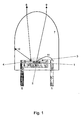
Der prinzipielle Aufbau einer weißen LED ist in
Zur Realisierung hoher äußerer Quantenausbeuten bringt man den Chip 1 in die verspiegelte Kalotte 6 ein, die als Hohlspiegel einen großen Teil der seitlichen und rückwärtsgerichteten Strahlung nach vorn reflektiert und fester Teil einer der Elektroden 5 ist. Damit weist die Injektionslumineszenz eine Richtcharakteristik auf, die durch den linsenförmigen Plastikdom 7 noch weiter gebündelt wird und Abstrahlwinkel von wenigen Grad bis zu 180° (in SMD-Bauelementen) erreichen kann.To realize high external quantum yields brings the
Diese Abstrahlcharakteristik wird kaum durch eine Phosphoreszenzschicht 4, die aus einem Gemisch der organischen oder anorganischen Farbstoffe mit Epoxidharz 6 besteht und die Kalotte abdeckt, verändert. Durch die Absorption eines Teils des primären blauen Lichtes der Injektionslumineszenz im Farbstoff 4 wird eine Photolumineszenz 8, 10 hervorgerufen, die wieder isotrop in den Raum emittiert wird. Durch den linsenartigen Plastikdom wird eine Formung der Photolumineszenz nur unvollständig möglich, so dass nur Strahlen 8 gebündelt werden und nach vorn den Linsendom verlassen können. Im Vergleich zur Injektionslumineszenz 9 wird wegen der unterschiedlichen Orte der Lichtentstehung die Photolumineszenz eine etwas andere Richtcharakteristik aufweisen. Beide Lichtarten, d. h. die blaue Injektionslumineszenz und die langweiligere Photolumineszenz, werden vom Auge des Beobachters gemeinsam wahrgenommen, so dass infolge der additiven Farbmischung ein mehr oder weniger weißes Licht beobachtet wird, das entsprechend dem Blauanteil Farbtemperaturen zwischen 5.000 K und 20.000 K aufweisen kann.This emission characteristic is hardly changed by a
Ein typisches Emissionsspektrum einer derartigen LED umfasst eine kurzwellige blaue Bande, die der Injektionslumineszenz entspricht, und eine langwelligere breitere Bande, die zur Photolumineszenz des Phosphors gehört.A typical emission spectrum of such an LED comprises a short wavelength blue band corresponding to the injection luminescence and a longer wavelength wider band pertaining to the photoluminescence of the phosphor.
Die Banden verändern sich mit dem Flussstrom. Bei gleichbleibender bzw. konstant gehaltener Empfindlichkeit des Empfängers erkennt man, daß die Kurve für 1 mA und die Kurve für 5 mA noch nicht voll ausgebildet sind. Verwendet man einen empfindlicheren Nachweisbereich, dann kann man den zu 10 mA und den zu 30 mA nahezu ebenbürtigen Zustand realisieren. Beim Einsatz der weißen LED muss man jedoch beachten, dass mit zunehmendem Flussstrom eine leichte Peakverschiebung zu beobachten ist. Da man aber meistens einen ausgewählten Flussstrom für eine Sensoreinstellung verwendet, spielt dies keine Rolle.The bands change with the flow stream. If the sensitivity of the receiver remains constant or constant, it can be seen that the curve for 1 mA and the curve for 5 mA are not yet fully developed. If one uses a more sensitive detection range, then one can realize the almost 10 mA and the almost equal to 30 mA state. When using the white LED, however, it must be noted that a slight peak shift can be observed with increasing flux current. But most of the time using a selected flow stream for a sensor setting does not matter.
Bedingt durch die geringfügig unterschiedlichen Entstehungsorte beider Lichtarten muss bei unterschiedlichen Betrachtungswinkeln eine farbliche Veränderung auftreten, d. h. die Farbkoordinaten ändern sich mit dem Betrachtungswinkel. Da die Strahlungsintensität in Zenit- bzw. Geradeausrichtung am größten ist, bemerkt man diesen Effekt nur bei zielgerichteter Beobachtung.Due to the slightly different places of origin of both types of light, a color change must occur at different viewing angles. H. the color coordinates change with the viewing angle. Since the radiation intensity is greatest in the zenith and straight-line direction, this effect is only noticed with targeted observation.
Durch mehrere Druckschriften (
Ziel der vorliegenden Erfindung ist es, die Auswertegenauigkeit solcher Verfahren und Vorrichtungen zu verbessern und zu vereinfachen.The aim of the present invention is to improve and simplify the evaluation accuracy of such methods and devices.
Zum Erreichen dieses Ziels werden erfindungsgemäß ein Verfahren mit den Merkmalen des Anspruchs 1 und eine Vorrichtung mit den Merkmalen des Anspruchs 12 angegebenTo achieve this aim, a method with the features of
Erfindungsgemäß wird das Ziel dadurch erreicht, dass die Veränderungen des Emissionsspektrums, zu denen die Peak-Intensitäten, die integralen Intensitäten des Gesamtspektrums und der ergänzten Einzelspektren der Injektionslumineszenz und der Photolumineszenz, die veränderten Anstiege der Flanken der Banden, die Verhältnisse der Peakwellenlängen und der integralen Intensitäten der Einzelspektren, die Verschiebung der Peakwellenlängen, verunreinigungsspezifische Absorptionen und selektive Anregungen von Verunreinigungen zur Fluoreszenz gehören, ausgewertet werden Erfindungsgemäß werden die Spektren inklusive der messbaren Veränderungen mit einem faseroptischen Kompaktspektrometer oder mit einem ähnlichen optoelektronischen Empfänger mittels Lichtwellenleiter nachgewiesen, wobei die Steuerung der Messprozedur, die Speicherung und die Bearbeitung sowie Auswertung mit einem Computer vorgenommen wird.According to the invention, the target is achieved by the changes in the emission spectrum, including the peak intensities, the integral intensities of the total spectrum and the supplemented individual spectra of the injection luminescence and the photoluminescence, the changed slopes of the edges of the bands, the ratios of the peak wavelengths and the integral Intensities of the individual spectra, the According to the spectra including the measurable changes with a fiber optic compact spectrometer or with a similar optoelectronic receiver are detected by means of optical waveguides, wherein the control of the measuring procedure, storage and processing as well as evaluation is done with a computer.
In der hier vorgestellten Erfindung wird im Gegensatz zu den bekannten Messmethoden immer ein eingrenzter Winkel der Abstrahlcharakteristik herangezogen, so dass der auftretende Fehler den Einsatz eines solchen Sensors nicht erschwert, zumal die Anfangsdaten der weißen LED nach Durchgang durch destilliertes Wasser oder Leitungswasser immer gespeichert und später zur Normierung herangezogen werden.In the invention presented here, in contrast to the known measuring methods is always a limited angle of the radiation used, so that the error does not complicate the use of such a sensor, especially since the initial data of the white LED after passing through distilled water or tap water always stored and later be used for normalization.
Für die Erfindung ist die Proportionalität der Intensität der primären Injektionslumineszenz zur Intensität der sekundären Photolumineszenz von entscheidender Bedeutung. Sie sollte im üblichen Betriebsbereich der LED, also im Bereich der Flussströme von etwa 0,1 mA bis 100 mA, hinreichend genau sein. Setzt man diese direkte Proportionalität in einem ausgewählten Flussstrombereich voraus, dann verändern sich die Intensitäten der Peakwellenlängen, die integralen Intensitäten beider Banden und die Halbwertsbreiten beider Emissionen gleichartig, d. h. man kann ohne ein modifizierendes Medium die Verhältnisse beider Banden als konstant betrachten. Das kann, wie oben schon bemerkt, immer zu Beginn der Messprozedur als Basiswert gespeichert werden.For the invention, the proportionality of the intensity of the primary injection luminescence to the intensity of the secondary photoluminescence is of crucial importance. It should be sufficiently accurate in the usual operating range of the LED, ie in the range of the flux currents of about 0.1 mA to 100 mA. Assuming this direct proportionality in a selected flux-current range, the intensities of the peak wavelengths, the integral intensities of both bands and the half-widths of both emissions change in a similar manner, ie. H. without a modifying medium one can regard the relations of both bands as constant. This can, as already noted above, always be stored as an underlying at the beginning of the measurement procedure.
Ein weiteres Problem beim Einsatz eines derartigen Sensors tritt infolge der Temperaturabhängigkeit der elektrischen Parameter von Halbleiterbauelementen auf. Setzt man voraus, dass unter Konstantstrombedingungen gearbeitet wird, dann ergibt sich für einen Flussstrom von etwa 5 mA ein Temperaturkoeffzient der Flußspannung Uf von etwa 2,2 mV/K für die temperaturbedingte Flussspannungsvariation. Nimmt man an, dass beispielsweise eine Waschmaschine in einem Temperaturintervall von 5 °C bis 80 °C eingesetzt wird, dann würde sich, wenn die weißen und anderen LED auch diese Temperatur annehmen, die Flussspannung bei konstantem Flussstrom um etwa 165 mV ändern.Another problem with the use of such a sensor arises due to the temperature dependence of the electrical parameters of semiconductor devices. Assuming that working under constant current conditions, then results for a flow of about 5 mA, a temperature coefficient of the forward voltage U f of about 2.2 mV / K for the temperature-induced Flussspannungsvariation. Assuming, for example, that a washing machine is used in a temperature range of 5 ° C to 80 ° C, then, if the white and other LED also assume this temperature, would change the forward voltage at constant flux current by about 165 mV.
Dieser Wert kann durch eine Konstantstromeinspeisung ohne weiteres verkraftet werden, so dass bei Verwendung einer geeigneten Versorgungsquelle die Temperaturabhängigkeit der Kennlinien keinen großen Einfluss auf die Arbeitsweise des Sensors ausüben kann. Aus dieser Temperaturabhängigkeit ergibt sich aber auch ein besonderer Vorteil des Einsatzes solcher Halbleiteremitter. Setzt man den obigen Temperaturkoeffizienten der Flussspannung bei konstantem Flussstrom If als bekannt voraus, dann kann in eine Regeleinheit zur Flussspannungskompensation sofort die Temperatur der LED eingegeben werden. Man hat also dadurch die Möglichkeit, Temperatureinflüsse zusätzlich zu gewinnen und sie sofort zur Korrektur der temperaturabhängigen Parameter zu nutzen.This value can be easily absorbed by a constant current feed, so that when using a suitable supply source, the temperature dependence of the characteristics can not exert a large influence on the operation of the sensor. From this temperature dependence but also gives a particular advantage of the use of such semiconductor emitter. Assuming the above temperature coefficient of the forward voltage at a constant flux current I f as known advance, then the temperature of the LED can be entered immediately in a control unit for Flussspannungskompensation. This gives you the opportunity to gain additional temperature effects and to use them immediately to correct the temperature-dependent parameters.
Beachtet muss jedoch ferner werden, dass auch die Rekombinationseigenschaften von Halbleiterinjektionsdioden infolge der temperaturabhängigen Bandlücke einen Temperaturgang aufweisen. Die Verschiebung der Peakwellenlänge von GalnN-LED besitzt im allgemeinen einen Temperaturkoeffizienten von etwa 0,06 nm/K (siehe [1]), während GaAlAs-IRED einen größeren Wert von etwa 0,12 nm/K aufweisen. Bei einem Einsatz im obigen Temperaturintervall würde sich für die blaue Bande der weißen LED eine Peakwellenlängenverschiebung von maximal 4,5 nm ergeben. Nimmt man Raumtemperatur von 22°C als Ausgangswert, würde die Peakwellenlänge der weißen LED und der UVED bis zu 80°C sich maximal um 3,5 nm ändern, was im Auflösungsbereich von faseroptischen Billigkompaktspektormetern liegt. Für die IRED ergäbe sich ein Wert von etwa 9 nm.However, it must also be noted that the recombination properties of semiconductor injection diodes also have a temperature response as a result of the temperature-dependent band gap. The shift of the peak wavelength of GaInN LED generally has a temperature coefficient of about 0.06 nm / K (see [1]), while GaAlAs-IRED has a larger value of about 0.12 nm / K. When used in the above temperature range, the blue band of the white LED would have a peak wavelength shift of at most 4.5 nm. Taking room temperature of 22 ° C as the initial value, the peak wavelength of the white LED and the UVED would change up to a maximum of 3.5 nm up to 80 ° C, which is within the resolution range of low-fiber optic compact spectrometers. For the IRED a value of about 9 nm would result.
Da die infrarote Bande sehr breit ist und ihr Spektrum immer nur als Vergleich herangezogen wird, ist die Peakverschiebung von untergeordneter Bedeutung. Die Abweichung der Peaks mit der Temperatur sollte jedoch in Ausnahmefällen bei der Auswertung der durch die Flüssigkeit mit ihren Verunreinigungen modifzierten Strahlung berücksichtigt werden, was durch die Temperaturangabe aus der oben diskutierten Flussspannungsänderung sofort möglich ist.Since the infrared band is very broad and their spectrum is always used only as a comparison, the peak shift is of secondary importance. However, the deviation of the peaks from the temperature should, in exceptional cases, be taken into account in the evaluation of the radiation modified by the liquid with its impurities, which is immediately possible by the temperature specification from the change in the flux voltage discussed above.
Die Erfindung betrifft nun die Nutzung solcher weißen LED, ergänzt durch UVED und/oder IRED, für den Nachweis von Verunreinigungszuständen und die Veränderung derselben in Flüssigkeiten derart, dass die LED an einem Bypass oder an einem Steig- bzw. Durchflussrohr, in denen eine ruhende Flüssigkeitssäule oder eine strömende Flüssigkeit vorhanden ist, angebracht werden, ihre Strahlungen nach dem Durchtritt durch die Flüssigkeit von einem Glas- oder Kunststofflichtlichtwellenleiter in ein faseroptisches Kompaktspektrometer oder in einen ähnlichen optoelektronischen Empfänger überführt werden und die Modifkation des transmittierten bzw. gestreuten Lichtes analysiert wird, wobei mindestens je eine LED in Geradeausrichtung und in 90°-Richtung angebracht werden und die Licht- bzw. Strahlungssignale gleichzeitig oder nacheinander an ein Spektrometer oder an einen ähnlichen optoelektronischen Empfänger gegeben werden. Je nach Schaltzustand wird eine Auswertung der licht- bzw. strahlungsemittierenden Dioden in Abhängigkeit vom Verunreinigungszustand der Flüssigkeit vorgenommen.The invention now relates to the use of such white LEDs, supplemented by UVED and / or IRED, for the detection of contaminant states and the alteration thereof in liquids such that the LED at a bypass or at a riser or flow tube, in which a dormant Liquid column or a flowing liquid is present, their radiation after passing through the liquid from a glass or plastic light optical fiber into a fiber optic Compact spectrometer or in a similar optoelectronic receiver are transferred and the modification of the transmitted or scattered light is analyzed, wherein at least one LED are mounted in the straight ahead and in the 90 ° direction and the light or radiation signals simultaneously or sequentially to a spectrometer or be given to a similar optoelectronic receiver. Depending on the switching state, an evaluation of the light- or radiation-emitting diodes is carried out as a function of the contamination state of the liquid.
Anhand von mehreren in der Zeichnung dargestellten Ausführungsbeispielen ist die Erfindung nachstehend erläutert. in der Zeichnung zeigen
- Fig. 1
- eine schematische Darstellung des Aufbaus einer weißen LED,
- Fig. 5
- eine Anordnung der LED in einem ersten Ausführungsbeispiel,
- Fig. 6
- eine Anordnung der licht- bzw. strahlungsemittierende Dioden in einem zweiten Ausführungsbeispiel.
- Fig. 1
- a schematic representation of the structure of a white LED,
- Fig. 5
- an arrangement of the LED in a first embodiment,
- Fig. 6
- an arrangement of the light or radiation-emitting diodes in a second embodiment.
Im ersten Ausführungsbeispiel nach
Das von der LED 21 ausgehende Licht 27 wird durch Absorptionen und Streuungen geschwächt. Da es leicht divergent ist, erfolgt auch noch eine Aufspreizung der Strahlen. In die Empfängerfaser gelangt also nur ein Bruchteil der von der LED 21 ausgehenden Strahlung. Die messbare transmittierte Strahlung wird sich mit der Art der Flüssigkeit und in Abhängigkeit von ihren Verunreinigungen und deren Konzentration mehr oder weniger stark ändern. Wenn in einer Flüssigkeit Verunreinigungen vorhanden sind, kann an ihnen das Licht gestreut und selektiv absorbiert werden, was in bestimmten Fällen sogar zur Fluoreszenz von Verunreinigungen führen kann.The light 27 emanating from the
Solche Fluoreszenzen zeigen sich dann als Spektrenveränderungen in den langwelligen Schultern der Banden. Die Streuung des Lichtes bzw. der Strahlung hängt nun von der Größe der Streuzentren, von ihrer Symmetrie, ihrem Brechungsindex und von ihrer Konzentration ab. Sind die Streuzentren wesentlich kleiner als die Wellenlänge der gestreuten Strahlung, dann kann die Streuintensität durch die Rayleigh-Theorie beschrieben werden, die eine symmetrische cos-artige Intensitätsverteilung mit Werten zwischen 1 und 2 aufweist, wobei auf Polarisationseffekte hier nicht eingegangen werden soll. Ihre Intensität ist für eine konstante Winkeleinstellung der Wellenlänge umgekehrt proportional (I(λ) = const. λ-n), wobei der Exponent n einen Wert von etwa 4,2 hat.Such fluorescences then show up as spectral changes in the long-wave shoulders of the bands. The scattering of light or radiation now depends on the Size of the scattering centers, their symmetry, their refractive index and their concentration. If the scattering centers are significantly smaller than the wavelength of the scattered radiation, then the scattering intensity can be described by the Rayleigh theory, which has a symmetrical cos-like intensity distribution with values between 1 and 2, whereby polarization effects should not be discussed here. Its intensity is inversely proportional for a constant angular adjustment of the wavelength (I (λ) = const. Λ -n ), where the exponent n has a value of about 4.2.
Um die gestreute Strahlung von der direkten Strahlung möglichst gut unterscheiden zu können, misst man häufig in 90°-Richtung. Da LED sehr billig sind und sich leicht elektronisch ein- und ausschalten lassen, wird anstelle des in 90°-Richtung notwendigen Lichtwellenleiters eine zweite weiße LED 22 angebracht, deren Strahlung 28 nicht direkt in den Lichtwellenleiter 23 gelangen kann, sondern von der schwarzen Wand 25 absorbiert wird. Dies hat auch den Vorteil, dass kein Multiplexer für die Lichtwellenleiter zum Spektrometer notwendig ist. Die gestreuten Strahlen 30 gelangen nun teilweise in den Lichtwellenleiter 23 und werden dem Empfänger zu geleitet.In order to be able to distinguish the scattered radiation from the direct radiation as well as possible, one often measures in the 90 ° direction. Since LEDs are very cheap and can be easily switched on and off electronically, a second
Das einfache Ein- und Ausschalten der LED 21 und 22 gestattet es nun, sowohl das direkte transmittierte, durch die Flüssigkeit modifizierte Licht zu messen als auch das gestreute Licht 30 der LED 22 in 90°-Richtung zu registrieren. Man kann also Streu- und Absorptionseinflüsse durch das Medium Flüssigkeit getrennt und beim Einschalten beider LED auch gleichzeitig nachweisen. Der letztere Fall ist eine additive Kontrollmessung und dient zum Vergleich der Signale der einzeln eingeschalteten LED.The simple switching on and off of the
Werden die Streuzentren größer und größer und wird ihr Durchmesser allmählich vergleichbar mit der Wellenlänge der Primärstrahlung oder gar größer als dieselbe, dann kann die Intensitätsverteilung durch die Mie-Theorie beschrieben werden. Diese mathematisch anspruchsvolle Theorie enthält als Ausgangsparameter nur die Brechungsindizes des Mediums und der Streuzentren, die Größe der Streuzentren und ihre Symmetrie und stellt die allgemeine Lösung des kombinierten Beugungs- und Absorptionsproblems von Verunreinigungen in Medien mit einem Brechungsindex, der sich von dem der Verunreinigungen unterscheiden muss, dar. Das Ergebnis erhält man durch Reihenentwicklungen komplizierter Funktionen, wobei die Reihen schlecht konvergieren und daher eine sehr große Anzahl von Gliedern berücksichtigt werden muss, was heute im Zeitalter der schnellen Computer keine Beschränkung mehr darstellt.If the scattering centers are larger and larger and their diameter gradually becomes comparable to the wavelength of the primary radiation or even larger than the same, then the intensity distribution can be described by the Mie theory. This mathematically demanding theory contains as starting parameters only the refractive indices of the medium and the scattering centers, the size of the scattering centers and their symmetry, and represents the general solution of the combined diffraction and absorption problem of impurities in media with a refractive index which must be different from that of the impurities The result is obtained by series development of complex functions, where the rows converge poorly and therefore a very large number of terms must be taken into account, which today is no longer a limitation in the age of fast computers.
Man erhält mit zunehmender Teilchengröße eine immer größere Intensität der gestreuten Strahlung in Vorwärtsrichtung bei gleichzeitiger schwacher Abhängigkeit von der Wellenlänge der verwendeten Strahlung, was dann gemäß
Nachfolgend ist eine Spektrenmodifikation einer weißen LED durch unterschiedliche Wässer erläutert. Im Vergleich mit dem LED-Spektrum für Leitungswasser oder für Flusswasser bei Niedrigwasserstand eines norddeutschen Flusses (bei Ebbe) zeigt das LED-Spektrum gemessen an schwach verschmutztem Wasser sowohl eine starke Abnahme des kurzwelligen Peaks als auch eine Peakwellenlängenverschiebung der langwelligen Bande.In the following a spectral modification of a white LED through different waters is explained. In comparison with the LED spectrum for tap water or for river water at low water level of a north German river (at low tide), the LED spectrum measured on lightly polluted water shows both a large decrease in the short wavelength peak and a peak wavelength shift of the long wavelength band.
Diese gemessenen prinzipiellen Verhaltensweisen treten bei nicht extrem stark verunreinigten Flüssigkeiten immer wieder auf. Eie zu hohe Verunreinigungskonzentration führt allerdings zu solch hohen Absorptionen, die kein direktes bzw. gestreutes Licht mehr passieren lassen und folglich keine Messung mehr ermöglichen.These measured principal behaviors occur again and again in non-extremely heavily contaminated liquids. However, an impurity concentration that is too high leads to such high absorptions that no more direct or scattered light can pass, and consequently no longer permit measurement.
Nachfolgend sind vier Spektren einer weißen LED erläutert, die an bewusst verunreinigtem Wasser aufgenommen wurden. Verglichen werden Spektren des normalen Leistungswassers (Berliner Wasser: Härte etwa 18°dH), und Spektren mit Verunreinigungen von Schmutz in Wasser, wobei der Schmutz nach unterschiedlichen Lösungszeiten aus Testgeweben von EMPA (St. Gallen) sich in Wasser löste. Ein weiteres Spektrum wurde dadurch gewonnen, dass noch zusätzlich Rotwein ins schon leicht verschmutzte Wasser gegeben wurde.Below are four white LED spectra recorded on deliberately contaminated water. Spectra of the normal performance water (Berlin water: hardness about 18 ° dH) and spectra with impurities of dirt in water are compared, the dirt after different dissolution times from test fabrics of EMPA (St. Gallen) dissolved in water. Another spectrum was gained by adding red wine to slightly contaminated water.
Man erkennt
- (i) eine Peakwellenlängenverschiebung des blauen Peaks,
- (ii) eine Verschiebung der maximalen Peakwellenlänge der langwelligeren Bande,
- (iii) eine unterschiedliche Abnahme der Intensitäten,
- (iv) veränderte Anstiege der kurzwelligen Flanken beider Banden, und
- (v) dass die Flächen der einzelnen Spektren sowie die Flächenverhält-nisse der rekonstruierten Einzelspektren (rekonstruierte gaußähnliche Kurven unter Berücksichtigung der Schiefe) unterschiedlich sind.
- (i) a peak wavelength shift of the blue peak,
- (ii) a shift of the maximum peak wavelength of the longer wavelength band,
- (iii) a different decrease in intensities,
- (iv) changes in the shortwave flanks of both bands, and
- (v) the areas of the individual spectra as well as the area ratios of the reconstructed single spectra (reconstructed Gaussian curves taking into account the skewness) are different.
Beispielsweise ändern sich die Peakverhältnisse zwischen der längerwelligen Bande zur blauen Emission der Kurven 47 bis 44 von 2,10 über 2,48 und 2,83 bis zu 3,30, was nach einer entsprechenden Eichung sehr gute Schwellenwerte für eine in-situ-Optimierung von Prozessen darstellt. Ähnliche Verhältnisse treten für die anderen genannten Parameter ebenfalls auf.For example, the peak ratios between the longer wavelength blue emission band of curves 47-44 change from 2.10 over 2.48 and 2.83 up to 3.30, which, after appropriate calibration, provide very good thresholds for in situ optimization of processes. Similar conditions also apply to the other parameters mentioned.
Das zweite Ausführungsbeispiel gemäß
Folgende Messabläufe sind nun wahlweise möglich:
- Analog zum ersten Beispiel sind auch alle Messarten wie oben diskutiert enthalten. Fügt man zu den weißen LED die IRED hinzu, dann können als Kontrolle immer die Infrarot(IR)-Spektren gemessen werden, was bei kaum verändertem IR-
Spektrum der IRED 34 aber stark verändertem Spektrum der weißenLED 33 eindeutige Aussagen zur Strahlungsstreuung zulässt. Ist die Lichtabsorption und Streuung schon sehr groß, gewinnt man zusätzlich aus den Daten der weißenLED 31 und derIRED 32 noch Aussagen zur Vorwärtsstreuung und der wellenlängenabhängigen Absorption, die infolge der unterschiedlichen Verunreinigungen im Infraroten eindeutig unterschiedlich zum Kurzwelligen ist. Setzt man anstelle der IRED auf diePositionen 32 und 33 UVED, dann lassen sich wirksame kurzwellige Absorptionen und insbesondere die im Kurzwelligen sehr wirksame Rayleigh-Streuung gut detektieren. Eine Kombination von je einer IRED und einer UVED erschließt letztendlich alle nachweisbaren Absorptionen und Streuungen in Geradeausrichtung und in 90°-Richtung. Da alle LED, IRED und UVED in Synchronisation mit dem Spektrometer vom Computer, der nicht in der Zeichnung nicht dargestellt ist, programmgemäß schnell schaltbar sind, kann bei kleinen Integrationszeiten in etwa einer Sekunde die Messung in allen Verknüpfungen ausgeführt werden. Der Kostenaufwand gegenüber dem ersten Ausführungsbeispiel ist vernachlässigbar (einige EURO), was die letztere Variante als universellen Sensor empfiehlt.
- Analogous to the first example, all types of measurement are included as discussed above. If the IRED is added to the white LED, then the infrared (IR) spectra can always be measured as a control, which allows unequivocal statements on radiation scattering with barely changed IR spectrum of the
IRED 34 but strongly changed spectrum of the white LED. If the light absorption and scattering is already very large, one additionally obtains from the data of thewhite LED 31 and theIRED 32 statements on the forward scattering and the wavelength-dependent absorption, which clearly differ due to the different impurities in the infrared Shortwave is. Substituting UVED forpositions
Ein weiteres Ausführungsbeispiel ausgehend von
(nm)
(r. E.)
(r. E.)
(nm)
(r.
(r.
Man erkennt sehr gut die geringere Transmission im Roten und die stärkere im Blauen. Wir haben es in diesem Falle mehr mit selektiver Absorption denn mit Streueffekten zu tun. Die Wertedifferenzen sind sehr groß; so können Sensoren gut angesprochen werden.You can see very well the lower transmission in the red and the stronger in the blue. In this case we are dealing more with selective absorption than with scattering effects. The value differences are very large; so sensors can be addressed well.
Die Peakverschiebung im Bereich der langwelligen Bande beträgt etwa 60 nm, was für einen Sensor ein sehr gut nachweisbares Signal darstellt. Zieht man noch die Flächen der kurzwelligen Bande von der kurzwelligen Grenze bis zum Minimum (etwa bei 490 nm) (Ab1 bis Ab4) und der langwelligen Bande von 490 nm bis ins nahe Infrarot (Ag1 bis Ag4) zu Rate, dann erhält man folgende Werte: ![]()
![]()
![]()
![]()
![]()
![]()
![]()
![]()
Auch die Anstiege der langwelligen Bande sind für die Verfolgung der Verunreinigungskonzentration und -art auswertbar. Sie ändern sich bei beispielsweise bei 517 nm folgendermaßen:
Wie man außerdem leicht erkennt, bleibt der langwellige Teil der Photolumineszenzbande von etwa 650 nm an nahezu unverfälscht konstant.It is also easy to see that the long-wavelength part of the photoluminescent band remains approximately unaltered from about 650 nm.
Damit stehen die Peakverschiebungen, die Anstiege der Banden, die Flächenverhältnisse, die Intensitätsverhältnisse, die Halbwertsbreiten (soweit erkennbar bzw. identifizierbar) und selektive Absorptionen und Emissionen für die Verunreinigungssensorik zur Verfügung.Thus, the peak shifts, the slopes of the bands, the area ratios, the intensity ratios, the half-widths (if detectable or identifiable) and selective absorptions and emissions are available for the contamination sensor system.
Eine weitere Stütze der genannten Ausführungsbeispiele ist durch Messungen an den Emissionen einer weißen LED und einer IRED an rotweinhaltigem Leitungswasser gegeben. Aus den Veränderungen der Spektren, hier tritt in der Bande kaum eine Absorption oder Streuung auf, kann man auf die Verunreinigung bzw. den Grad der "Verschmutzung" schließen.Another support of the aforementioned embodiments is given by measurements on the emissions of a white LED and an IRED of red wine-containing tap water. From the changes of the spectra, here in the band hardly any absorption or scattering occurs, one can conclude on the pollution or the degree of "pollution".
Das bringen auch Streuspektren zum Ausdruck. Sie wurden an milchhaltigem Wasser aufgenommen. Dargestellt sind die Intensitäten der 90°-Streuung in r. E. Während das Spektrum der weißen LED stark modifiziert wurde, treten in der IR-Bande keine wesentlichen Strukturänderungen auf. Wir haben es in diesem Falle mit der nahezu wellenlängenunabhängigen Mie-Streuung zu tun. Aus den Veränderungen der Spektren in Bezug auf "reines" Leitungswasser lassen sich eindeutige Aussagen zum Grad und zur Art der "Verschmutzung" machen.This is also reflected by scattered spectra. They were taken up in milk-containing water. Shown are the intensities of the 90 ° scattering in r. E. While the spectrum of the white LED has been heavily modified, there are no significant structural changes in the IR band. In this case, we are dealing with almost wavelength-independent Mie scattering. The changes in the spectra in relation to "pure" tap water make it possible to make clear statements about the degree and type of "pollution".
Ein weiteres Anwendungsbeispiel wird nachfolgend veranschaulicht. Hier wurden eine weiße LED und eine UVED in den Positionen 31 und 32 der
Bezeichnet man die Intensitäten der Maxima der einzelnen Banden mit I1 bis I5 vom Kurzwelligen angefangen, dann erhält man für Leitungswasser bzw. für Flusswasser folgende Daten.
Aus dem Vergleich der obigen Wertetabelle erkennt man, dass die Daten der 2. Ordnung für die UVED nahezu gleiche Werte liefern, dass aber der Wert beim Flusswasser infolge der Streuung im UV abgeschwächt gegenüber dem normalen Wasser ist. Bei der 2. Ordnung der blauen Bande tritt nur noch eine sehr geringe Abweichung in der 2. Ordnung gegenüber bei normalem Wasser auf, was auf einen schwachen Streueffekt im Blauen hindeutet, aber auch durch Messfehler teilweise bedingt sein kann. Wie oben also schon angedeutet, kann die jeweils 2. Ordnung der UVED und der blauen Bande der weißen LED helfen, Streueinflüsse sehr schnell zu erkennen. Im übrigen sind die Differenzen zwischen den unterschiedlichen Wässern in nahezu allen Verhältnissen relativ groß, so dass bei entsprechenden Eichungen eindeutige Schwellenwerte für Prozeßoptimierungen und Steuerungen sowie Überwachungen zur Verfügung stehen.From the comparison of the above table of values, it can be seen that the 2nd order data for the UVED provide nearly equal values, but that the value of the flux water due to the scattering in the UV is attenuated compared to the normal water. In the second order of the blue band, there is only a very small deviation in the second order compared to normal water, which is a weak one Indicates scattering effect in the blue, but can also be partially caused by measurement errors. As already indicated above, the second order of the UVED and the blue band of the white LED can help to detect scattering influences very quickly. Incidentally, the differences between the different waters in almost all circumstances are relatively large, so that with appropriate calibrations clear thresholds for process optimization and control and monitoring available.
-
[1]
S. Nakamura and G. Fasol: "The Blue Laser Diode", Springer-Verlag, Berlin 1997 S. Nakamura and G. Fasol: "The Blue Laser Diode", Springer-Verlag, Berlin 1997 -
[2]
P. Schlotter, R. Schmidt and J. Schneider: "Luminescence or blue light emitting diodes", Appl. Phys. A64(1997), pg. 417-418 Schlotter, R. Schmidt and J. Schneider: "Luminescence or blue light emitting diodes", Appl. Phys. A64 (1997), pg. 417-418 -
[3]
DE 196 25 622 A1 DE 196 25 622 A1 -
[4]
DE 196 38 667 A1 DE 196 38 667 A1 -
[5]
J. Baur, P. Schlotter and J. Schneider: "White light emitting diode", Festkörperprobleme 37(1998), 67-78 J. Baur, P. Schlotter and J. Schneider: "White Light-emitting Diode", Festkörperprobleme 37 (1998), 67-78
Claims (18)
- Method for in situ determination and monitoring of contamination states of liquids (26) and/or and additionally for the checking of liquid levels by at least two light sources (21, 22, 31, 33; 32, 34) and a spectrometer or a similar optoelectronic receiver at a riser pipe or throughflow pipe (24) or at a bypass (24), wherein the emission spectrum, which is modified by the liquid (26) and/or by the contaminants intentionally or unintentionally introduced into the liquid (26), of the light sources (21, 22, 31, 33; 32, 34) is evaluated,
characterised in that- the light sources (21, 22, 31, 33; 32, 34) comprise a white-light emitting diode (21, 22, 31, 33) as well as additionally thereto a semiconductor injection diode (32, 34) emitting infrared or ultraviolet radiation,- wherein the white-light emitting diode (21, 22, 31, 33) has an injection luminescence and a photoluminescence, the intensities of which have within a selected flux range, particularly in the range of fluxes of 0.1 mA to 100 mA, a proportionality which is sufficiently precise,- the radiations (27, 28, 35, 36, 37, 38) of the light sources (21, 22, 31, 33; 32, 34) after passage through the liquid (26) are transmitted by an optical waveguide (23) or an optical conductor to the spectrometer or the similar optoelectronic receiver and- the modification of the transmitted and dispersed radiation (30) of the light sources (21, 22, 31, 33; 32, 34) is evaluated in dependence on the switch-on and switch-off state of the light sources (21, 22, 31, 33; 32, 34) and in dependence on the position of the light sources (21, 22, 31, 33; 32, 34). - Method according to claim 1, characterised in that a respective radiation, which is generated by a white-light emitting diode (21, 22, 31, 33), is radiated into the bypass (24) or the riser pipe or throughflow pipe (24) displaced through 90° so as to be able to measure not only the transmission, but also the dispersion spectra in 90° direction.
- Method according to claim 2, characterised in that - for better evidencing of the wavelength-dependent radiation dispersion - in addition, in parallel with that by the white-light emitting diode (21, 22, 31, 33), radiation of a respective ultraviolet diode (UVED) (32, 34) is radiated in, which then leads to even clearer dispersion evidence, since the dispersion intensity rapidly increases with decreasing wavelengths.
- Method according to claim 2 or 3, characterised in that in addition, in parallel to the radiation generated by the white-light emitting diode (21, 22, 31, 33), radiation of a respective IRED (32, 34) is radiated in so that the wavelength-dependent absorption and dispersion processes in consequence of the contaminations can be more clearly interpreted.
- Method according to claim 3 or 4, characterised in that the flux voltage at a constant flux of one of the white-light emitting diodes (21, 22, 31, 33) or also the other IREDs (32, 34) or UVEDs (32, 34) used is monitored and correlated and a temperature statement is obtained therefrom and flux voltage changes are utilised for correction of the temperature-dependent spectral displacement by way of a regulating element.
- Method according to any one of claims 3 to 5, characterised in that alternately to the radiations of the white-light emitting diodes (21, 22, 31, 33) a respective radiation of a UVED (32, 34) and an IRED (32, 34) is radiated in in order to provide not only dispersion processes, but also absorption processes for checking and regulation.
- Method according to any one of the preceding claims, characterised in that the flux voltages for the LEDs (21, 22, 31, 33), UVEDs (32, 34) and IREDs (32, 34) are pulsed so that radiation changes due to surface changes in the measuring containers (24) can be perceived.
- Method according to any one of the preceding claims, characterised in that the flux voltages of the LEDs (21, 22, 31, 33), UVEDs (32, 34) and IREDs (32, 34) are modulated so as to be able to differentiate different groups of emitters by selectively sensitive amplifiers and/or receivers.
- Method according to any one of the preceding claims, characterised in that the peaks, peak displacements, integral intensities, peak relationships to one another, changed rises of all flanks of the bands, integral intensities of the blue spectrum of the injection luminescence and of the spectrum of the photoluminescence of the Gaussian-supplemented plots and half-widths from the spectrometer data are evaluated in situ by a rapid PC by which in addition an optimisation and/or control of the continuing process is carried out.
- Method according to claim 9, characterised in that the respective 2nd order of each spectrum is utilised for evaluation and, in particular, for intensity comparison.
- Method according to claim 10, characterised in that the spectra are, for example, divided by one another or subtracted in forward direction when change in the liquid state occurs, for example change in the contaminations and concentrations thereof, so that the dispersion and absorption changes can be made better visible.
- Device for in situ determination and monitoring of contamination states of liquids (26) and/or and additionally for the checking of liquid levels, comprising at least two light sources (21, 22, 31, 33; 32, 34), a spectrometer (34) or a similar optoelectronic receiver at a riser pipe or throughflow pipe (24) or at a bypass (24) and a computer for evaluation of the emission spectrum, which is modified by the liquid (26) and/or by the contaminations intentionally or unintentionally introduced into the liquid (26), of the light sources (21, 22, 31, 33; 32, 34),
characterised in that- the light sources (21, 22, 31, 33; 32, 34) comprise a white-light emitting diode (21, 22, 31, 33) as well as additionally thereto a semiconductor injection diode (32, 34) emitting infrared or ultraviolet radiation,- wherein the white-light emitting diode (21, 22, 31, 33) has an injection luminescence and a photoluminescence, the intensities of which have within a selected flux range, particularly in the range of fluxes of 0.1 mA to 100 mA, a proportionality which is sufficiently precise,- an optical waveguide (23) or optical conductor is included, by means of which the radiations (27, 28, 35, 36, 37, 38) of the light sources (21, 22, 31, 33; 32, 34) are transmissible to the spectrometer or to the similar optoelectronic receiver by the optical waveguide (23) or the optical conductor after passage through the liquid (26) and- the computer is constructed for evaluation of the modification of the transmitted and dispersed radiation (30) of the light sources (21, 22, 31, 33; 32, 34) in dependence on the switch-on and switch-off state of the light sources (21, 22, 31, 33; 32, 34) and in dependence on the position of the light sources (21, 22, 31, 33; 32, 34). - Device according to claim 12, characterised in that at least two white-light emitting diodes (21, 22, 31, 33) are mounted at the bypass (24) or riser pipe or throughflow pipe (24) to be offset relative to one another by 90°.
- Device according to claim 13, characterised in that in addition a respective ultraviolet diode (UVED) (32, 34) is mounted in parallel to the white-light emitting diode (21, 22, 31, 33).
- Device according to claim 13 or 14, characterised in that in addition a respective IRED (32, 34) is mounted in parallel to the white-light emitting diode 21, 22, 31, 33).
- Device according to claim 14 or 15, characterised in that alternately a respective UVED (32, 34) and IRED (32, 34) are mounted in parallel to the white-light emitting diode (21, 22, 31, 33).
- Device according to any one of claims 13 to 16, characterised in that a transparent region (29), which is surrounded by a blackened region (25) at the container (24), is provided for each radiation emitter (21, 22, 31, 33; 32, 34) at the bypass (24) or at the riser pipe or throughflow pipe (24).
- Device according to any one of claims 13 to 16, characterised in that at least a part of the radiation emitter (21, 22, 31, 33; 32, 34) is arranged remotely from the measuring container (24) and is optically coupled with the coupling-in points (29) at the measuring container (24) by way of optical waveguides (34) of quartz, glass or plastic
Applications Claiming Priority (3)
| Application Number | Priority Date | Filing Date | Title |
|---|---|---|---|
| DE10305093A DE10305093A1 (en) | 2003-02-07 | 2003-02-07 | Method and device for determining and monitoring contamination states of different liquids |
| DE10305093 | 2003-02-07 | ||
| PCT/EP2004/001170 WO2004070369A1 (en) | 2003-02-07 | 2004-02-09 | Method and devices for determining and monitoring impurity states in different fluids |
Publications (2)
| Publication Number | Publication Date |
|---|---|
| EP1595137A1 EP1595137A1 (en) | 2005-11-16 |
| EP1595137B1 true EP1595137B1 (en) | 2010-04-28 |
Family
ID=32730872
Family Applications (1)
| Application Number | Title | Priority Date | Filing Date |
|---|---|---|---|
| EP04709217A Expired - Lifetime EP1595137B1 (en) | 2003-02-07 | 2004-02-09 | Method and devices for determining and monitoring impurity states in different fluids |
Country Status (4)
| Country | Link |
|---|---|
| EP (1) | EP1595137B1 (en) |
| AT (1) | ATE466277T1 (en) |
| DE (2) | DE10305093A1 (en) |
| WO (1) | WO2004070369A1 (en) |
Cited By (2)
| Publication number | Priority date | Publication date | Assignee | Title |
|---|---|---|---|---|
| DE102016217031A1 (en) | 2016-09-07 | 2018-03-08 | BSH Hausgeräte GmbH | Method for operating a washing machine or a washer-dryer with improved control and suitable for this purpose washing machine or suitable washer-dryer |
| US10488332B2 (en) | 2015-05-28 | 2019-11-26 | BSH Hausgeräte GmbH | Device and method for determining the dirt load in a rinsing or detergent solution |
Families Citing this family (4)
| Publication number | Priority date | Publication date | Assignee | Title |
|---|---|---|---|---|
| DE102004057957A1 (en) * | 2004-11-30 | 2006-06-08 | Endress + Hauser Conducta Gesellschaft für Mess- und Regeltechnik mbH + Co. KG | Turbidity sensor comprises infrared/blue light emitting diode with a luminescence transducer, measuring photo receiver, circuit for the operation in each diode in the pulse process and an analysis circuit signals emitted by the detector |
| EP1987762A1 (en) | 2007-05-03 | 2008-11-05 | F.Hoffmann-La Roche Ag | Oximeter |
| DE202008003977U1 (en) * | 2008-02-26 | 2009-07-02 | Bürkert Werke GmbH & Co. KG | microspectrometer |
| EP2246692B1 (en) | 2009-04-30 | 2012-02-08 | F. Hoffmann-La Roche AG | Method for detecting impurities in an optical measuring cuvette |
Family Cites Families (18)
| Publication number | Priority date | Publication date | Assignee | Title |
|---|---|---|---|---|
| DE3129065C1 (en) * | 1981-07-23 | 1982-11-11 | Gustav F. Gerdts GmbH & Co KG, 2800 Bremen | Device for photoelectric monitoring of a flowing medium |
| DE4336520C2 (en) * | 1993-10-26 | 1998-07-23 | Siemens Ag | Optical sensor and its use |
| JPH11503236A (en) * | 1995-04-06 | 1999-03-23 | アルファ・ラヴァル・アグリ・アクチボラゲット | Method and apparatus for quantitatively determining particles in fluid |
| DE19521326A1 (en) * | 1995-06-12 | 1996-12-19 | Bosch Siemens Hausgeraete | Method for temperature compensation of the measured values of a turbidity sensor in an automatic washing machine or dishwasher |
| DE19608866C2 (en) * | 1996-03-07 | 1998-11-26 | Eaton Gmbh | Measuring device for the liquid level in a container, in particular in a washing machine or dishwasher |
| DE29702220U1 (en) * | 1996-03-15 | 1997-11-13 | Karlsruhe Forschzent | Optical arrangement |
| DE19625622A1 (en) * | 1996-06-26 | 1998-01-02 | Siemens Ag | Light radiating semiconductor constructional element |
| AU5547798A (en) * | 1996-11-15 | 1998-06-10 | Optosens Optische Spektroskopie Und Sensortechnik Gmbh | Method and device for combined absorption and reflectance spectroscopy |
| DE19806560B4 (en) * | 1998-02-17 | 2007-08-23 | BSH Bosch und Siemens Hausgeräte GmbH | Method and device for washing and / or rinsing laundry in washing machines or washer-dryers |
| DE19806559B4 (en) * | 1998-02-17 | 2015-10-29 | BSH Hausgeräte GmbH | Method and device for treating dishes in dishwashers |
| DE19812289C2 (en) * | 1998-03-20 | 2003-05-28 | Karlsruhe Forschzent | Device for the photoelectric monitoring of flow medium by means of UV light |
| DE19821956A1 (en) * | 1998-05-16 | 1999-11-18 | Deutsch Zentr Luft & Raumfahrt | Method for the quantitative analysis of gas volumes, in particular exhaust gases from combustion devices or systems, and devices for carrying out the method |
| DE19831688C1 (en) * | 1998-07-15 | 2000-04-06 | Whirlpool Co | Optical sensor |
| DE19857845A1 (en) * | 1998-12-15 | 2000-06-21 | Bsh Bosch Siemens Hausgeraete | Device for detecting the liquid level in a container |
| EP1111333A4 (en) * | 1999-06-29 | 2002-08-28 | Omron Tateisi Electronics Co | Light source device, spectroscope comprising the light source device, and film thickness sensor |
| DE10008517C2 (en) * | 2000-02-24 | 2002-09-26 | Eppendorf Ag | Optical measuring system |
| DE10039765A1 (en) * | 2000-08-16 | 2002-02-28 | Volkswagen Ag | Device for determining the level of a filling medium in a tank comprises light sender and receiver units with their respective elements arranged at a definite pitch in the level measurement direction |
| DE10118449C1 (en) * | 2001-04-12 | 2002-10-17 | Mwg Biotech Ag | Device for monitoring a chemical stream used in the synthesis of DNA comprises a base body having a tubular recess, light measuring paths represented by light sources and a light |
-
2003
- 2003-02-07 DE DE10305093A patent/DE10305093A1/en not_active Ceased
-
2004
- 2004-02-09 EP EP04709217A patent/EP1595137B1/en not_active Expired - Lifetime
- 2004-02-09 AT AT04709217T patent/ATE466277T1/en active
- 2004-02-09 DE DE502004011097T patent/DE502004011097D1/en not_active Expired - Lifetime
- 2004-02-09 WO PCT/EP2004/001170 patent/WO2004070369A1/en active Application Filing
Cited By (3)
| Publication number | Priority date | Publication date | Assignee | Title |
|---|---|---|---|---|
| US10488332B2 (en) | 2015-05-28 | 2019-11-26 | BSH Hausgeräte GmbH | Device and method for determining the dirt load in a rinsing or detergent solution |
| DE102016217031A1 (en) | 2016-09-07 | 2018-03-08 | BSH Hausgeräte GmbH | Method for operating a washing machine or a washer-dryer with improved control and suitable for this purpose washing machine or suitable washer-dryer |
| EP3293298A1 (en) | 2016-09-07 | 2018-03-14 | BSH Hausgeräte GmbH | Method for operating a washing machine or a drying machine with improved control, as well as appropriate washing machine or dryer |
Also Published As
| Publication number | Publication date |
|---|---|
| WO2004070369A1 (en) | 2004-08-19 |
| DE502004011097D1 (en) | 2010-06-10 |
| ATE466277T1 (en) | 2010-05-15 |
| EP1595137A1 (en) | 2005-11-16 |
| DE10305093A1 (en) | 2004-08-19 |
Similar Documents
| Publication | Publication Date | Title |
|---|---|---|
| DE112011103113B4 (en) | Reflectivity measurement method, membrane thickness measurement device and membrane thickness measurement method | |
| DE102006040790B4 (en) | Reflex coupler with integrated organic light emitter and use of such a reflex coupler | |
| EP2065698B1 (en) | Chip for analysing a medium with integrated organic light emitter and process of manufacturing such a chip | |
| EP3574530B1 (en) | Optical smoke detection based on the two colour principle using a light emitting diode with an led chip for light emission and with a light converter for converting a part of the emitted light to longer wave light | |
| DE102012215702A1 (en) | lighting device | |
| DE102013107019A1 (en) | Lighting system for light emitting diode with gas detection function | |
| DE112016004726T5 (en) | Distance measuring device | |
| EP1595137B1 (en) | Method and devices for determining and monitoring impurity states in different fluids | |
| DE4434266A1 (en) | Method for temperature compensation of optoelectronic components and in particular of optoelectronic semiconductors | |
| DE112014005877B4 (en) | Light-emitting element, reference light source and method for observing a luminous body | |
| DE10257238B9 (en) | Method and device for the characterization of impurities in liquids | |
| EP1265198A2 (en) | Device and method for investigating documents | |
| DE102006004005A1 (en) | Infrared gas detector and method for detecting a gas concentration | |
| EP2215504A1 (en) | Apparatus for optical detection of impurities in longitudinally moving yarn | |
| DE10360563A1 (en) | Fluid contamination measurement procedure records selectively filtered transmitted and scatter light in visible, UV and IR regions as function of contamination level | |
| EP2288902B1 (en) | Apparatus for determining the element coverage on a glass surface using fluorescence | |
| DE10221823A1 (en) | Measuring liquid level, degree of fouling of water, other transparent liquids involves passing different emission spectra through liquid, acquiring modified spectra, feeding to optoelectronic receiver | |
| DE102013207479B3 (en) | Method for the rapid determination of the absolute luminescence intensity | |
| DE102017101678A1 (en) | Laser light with a sensor | |
| EP2887038A1 (en) | Fibre optic measuring device | |
| DE102018213377A1 (en) | Spectrometer and spectrometer calibration method | |
| WO2000005555A1 (en) | Method for testing the functionality of a spectrometer, and a spectrometer comprising a fault recognition device | |
| WO2016162398A1 (en) | Apparatus for detecting electronic faults on silicon-based semiconductor wafers | |
| WO2022135803A1 (en) | Optochemical sensor and method for measuring luminescing analytes in a measurement medium | |
| WO2014029733A2 (en) | Optoelectronic sensor, optoelectronic component comprising an optoelectronic sensor and method for operating an optoelectronic sensor |
Legal Events
| Date | Code | Title | Description |
|---|---|---|---|
| PUAI | Public reference made under article 153(3) epc to a published international application that has entered the european phase |
Free format text: ORIGINAL CODE: 0009012 |
|
| 17P | Request for examination filed |
Effective date: 20050907 |
|
| AK | Designated contracting states |
Kind code of ref document: A1 Designated state(s): AT BE BG CH CY CZ DE DK EE ES FI FR GB GR HU IE IT LI LU MC NL PT RO SE SI SK TR |
|
| AX | Request for extension of the european patent |
Extension state: AL LT LV MK |
|
| RIN1 | Information on inventor provided before grant (corrected) |
Inventor name: ZIERKE, FRITZ Inventor name: KLOSE, HEINZ Inventor name: MALCHER, STEPHAN |
|
| DAX | Request for extension of the european patent (deleted) | ||
| 17Q | First examination report despatched |
Effective date: 20070207 |
|
| GRAP | Despatch of communication of intention to grant a patent |
Free format text: ORIGINAL CODE: EPIDOSNIGR1 |
|
| GRAS | Grant fee paid |
Free format text: ORIGINAL CODE: EPIDOSNIGR3 |
|
| GRAA | (expected) grant |
Free format text: ORIGINAL CODE: 0009210 |
|
| AK | Designated contracting states |
Kind code of ref document: B1 Designated state(s): AT BE BG CH CY CZ DE DK EE ES FI FR GB GR HU IE IT LI LU MC NL PT RO SE SI SK TR |
|
| REG | Reference to a national code |
Ref country code: GB Ref legal event code: FG4D Free format text: NOT ENGLISH |
|
| REG | Reference to a national code |
Ref country code: CH Ref legal event code: EP |
|
| REG | Reference to a national code |
Ref country code: IE Ref legal event code: FG4D Free format text: LANGUAGE OF EP DOCUMENT: GERMAN |
|
| REF | Corresponds to: |
Ref document number: 502004011097 Country of ref document: DE Date of ref document: 20100610 Kind code of ref document: P |
|
| REG | Reference to a national code |
Ref country code: NL Ref legal event code: VDEP Effective date: 20100428 |
|
| PG25 | Lapsed in a contracting state [announced via postgrant information from national office to epo] |
Ref country code: SE Free format text: LAPSE BECAUSE OF FAILURE TO SUBMIT A TRANSLATION OF THE DESCRIPTION OR TO PAY THE FEE WITHIN THE PRESCRIBED TIME-LIMIT Effective date: 20100428 Ref country code: NL Free format text: LAPSE BECAUSE OF FAILURE TO SUBMIT A TRANSLATION OF THE DESCRIPTION OR TO PAY THE FEE WITHIN THE PRESCRIBED TIME-LIMIT Effective date: 20100428 Ref country code: ES Free format text: LAPSE BECAUSE OF FAILURE TO SUBMIT A TRANSLATION OF THE DESCRIPTION OR TO PAY THE FEE WITHIN THE PRESCRIBED TIME-LIMIT Effective date: 20100808 |
|
| REG | Reference to a national code |
Ref country code: IE Ref legal event code: FD4D |
|
| PG25 | Lapsed in a contracting state [announced via postgrant information from national office to epo] |
Ref country code: SI Free format text: LAPSE BECAUSE OF FAILURE TO SUBMIT A TRANSLATION OF THE DESCRIPTION OR TO PAY THE FEE WITHIN THE PRESCRIBED TIME-LIMIT Effective date: 20100428 Ref country code: FI Free format text: LAPSE BECAUSE OF FAILURE TO SUBMIT A TRANSLATION OF THE DESCRIPTION OR TO PAY THE FEE WITHIN THE PRESCRIBED TIME-LIMIT Effective date: 20100428 |
|
| PG25 | Lapsed in a contracting state [announced via postgrant information from national office to epo] |
Ref country code: GR Free format text: LAPSE BECAUSE OF FAILURE TO SUBMIT A TRANSLATION OF THE DESCRIPTION OR TO PAY THE FEE WITHIN THE PRESCRIBED TIME-LIMIT Effective date: 20100729 Ref country code: CY Free format text: LAPSE BECAUSE OF FAILURE TO SUBMIT A TRANSLATION OF THE DESCRIPTION OR TO PAY THE FEE WITHIN THE PRESCRIBED TIME-LIMIT Effective date: 20100428 |
|
| PG25 | Lapsed in a contracting state [announced via postgrant information from national office to epo] |
Ref country code: IE Free format text: LAPSE BECAUSE OF FAILURE TO SUBMIT A TRANSLATION OF THE DESCRIPTION OR TO PAY THE FEE WITHIN THE PRESCRIBED TIME-LIMIT Effective date: 20100428 Ref country code: DK Free format text: LAPSE BECAUSE OF FAILURE TO SUBMIT A TRANSLATION OF THE DESCRIPTION OR TO PAY THE FEE WITHIN THE PRESCRIBED TIME-LIMIT Effective date: 20100428 Ref country code: EE Free format text: LAPSE BECAUSE OF FAILURE TO SUBMIT A TRANSLATION OF THE DESCRIPTION OR TO PAY THE FEE WITHIN THE PRESCRIBED TIME-LIMIT Effective date: 20100428 Ref country code: PT Free format text: LAPSE BECAUSE OF FAILURE TO SUBMIT A TRANSLATION OF THE DESCRIPTION OR TO PAY THE FEE WITHIN THE PRESCRIBED TIME-LIMIT Effective date: 20100830 |
|
| PG25 | Lapsed in a contracting state [announced via postgrant information from national office to epo] |
Ref country code: SK Free format text: LAPSE BECAUSE OF FAILURE TO SUBMIT A TRANSLATION OF THE DESCRIPTION OR TO PAY THE FEE WITHIN THE PRESCRIBED TIME-LIMIT Effective date: 20100428 Ref country code: CZ Free format text: LAPSE BECAUSE OF FAILURE TO SUBMIT A TRANSLATION OF THE DESCRIPTION OR TO PAY THE FEE WITHIN THE PRESCRIBED TIME-LIMIT Effective date: 20100428 Ref country code: RO Free format text: LAPSE BECAUSE OF FAILURE TO SUBMIT A TRANSLATION OF THE DESCRIPTION OR TO PAY THE FEE WITHIN THE PRESCRIBED TIME-LIMIT Effective date: 20100428 |
|
| PLBE | No opposition filed within time limit |
Free format text: ORIGINAL CODE: 0009261 |
|
| STAA | Information on the status of an ep patent application or granted ep patent |
Free format text: STATUS: NO OPPOSITION FILED WITHIN TIME LIMIT |
|
| 26N | No opposition filed |
Effective date: 20110131 |
|
| BERE | Be: lapsed |
Owner name: BSH BOSCH UND SIEMENS HAUSGERATE G.M.B.H. Effective date: 20110228 |
|
| PG25 | Lapsed in a contracting state [announced via postgrant information from national office to epo] |
Ref country code: MC Free format text: LAPSE BECAUSE OF NON-PAYMENT OF DUE FEES Effective date: 20110228 |
|
| REG | Reference to a national code |
Ref country code: CH Ref legal event code: PL |
|
| PG25 | Lapsed in a contracting state [announced via postgrant information from national office to epo] |
Ref country code: CH Free format text: LAPSE BECAUSE OF NON-PAYMENT OF DUE FEES Effective date: 20110228 Ref country code: LI Free format text: LAPSE BECAUSE OF NON-PAYMENT OF DUE FEES Effective date: 20110228 |
|
| PG25 | Lapsed in a contracting state [announced via postgrant information from national office to epo] |
Ref country code: BE Free format text: LAPSE BECAUSE OF NON-PAYMENT OF DUE FEES Effective date: 20110228 |
|
| PGFP | Annual fee paid to national office [announced via postgrant information from national office to epo] |
Ref country code: FR Payment date: 20120228 Year of fee payment: 9 |
|
| PGFP | Annual fee paid to national office [announced via postgrant information from national office to epo] |
Ref country code: DE Payment date: 20120229 Year of fee payment: 9 |
|
| PGFP | Annual fee paid to national office [announced via postgrant information from national office to epo] |
Ref country code: IT Payment date: 20120223 Year of fee payment: 9 Ref country code: GB Payment date: 20120222 Year of fee payment: 9 |
|
| REG | Reference to a national code |
Ref country code: AT Ref legal event code: MM01 Ref document number: 466277 Country of ref document: AT Kind code of ref document: T Effective date: 20110209 |
|
| PG25 | Lapsed in a contracting state [announced via postgrant information from national office to epo] |
Ref country code: AT Free format text: LAPSE BECAUSE OF NON-PAYMENT OF DUE FEES Effective date: 20110209 |
|
| PG25 | Lapsed in a contracting state [announced via postgrant information from national office to epo] |
Ref country code: LU Free format text: LAPSE BECAUSE OF NON-PAYMENT OF DUE FEES Effective date: 20110209 |
|
| PG25 | Lapsed in a contracting state [announced via postgrant information from national office to epo] |
Ref country code: BG Free format text: LAPSE BECAUSE OF FAILURE TO SUBMIT A TRANSLATION OF THE DESCRIPTION OR TO PAY THE FEE WITHIN THE PRESCRIBED TIME-LIMIT Effective date: 20100728 Ref country code: TR Free format text: LAPSE BECAUSE OF FAILURE TO SUBMIT A TRANSLATION OF THE DESCRIPTION OR TO PAY THE FEE WITHIN THE PRESCRIBED TIME-LIMIT Effective date: 20100428 |
|
| GBPC | Gb: european patent ceased through non-payment of renewal fee |
Effective date: 20130209 |
|
| PG25 | Lapsed in a contracting state [announced via postgrant information from national office to epo] |
Ref country code: HU Free format text: LAPSE BECAUSE OF FAILURE TO SUBMIT A TRANSLATION OF THE DESCRIPTION OR TO PAY THE FEE WITHIN THE PRESCRIBED TIME-LIMIT Effective date: 20100428 |
|
| REG | Reference to a national code |
Ref country code: FR Ref legal event code: ST Effective date: 20131031 |
|
| REG | Reference to a national code |
Ref country code: DE Ref legal event code: R119 Ref document number: 502004011097 Country of ref document: DE Effective date: 20130903 |
|
| PG25 | Lapsed in a contracting state [announced via postgrant information from national office to epo] |
Ref country code: IT Free format text: LAPSE BECAUSE OF NON-PAYMENT OF DUE FEES Effective date: 20130209 |
|
| PG25 | Lapsed in a contracting state [announced via postgrant information from national office to epo] |
Ref country code: GB Free format text: LAPSE BECAUSE OF NON-PAYMENT OF DUE FEES Effective date: 20130209 Ref country code: FR Free format text: LAPSE BECAUSE OF NON-PAYMENT OF DUE FEES Effective date: 20130228 Ref country code: DE Free format text: LAPSE BECAUSE OF NON-PAYMENT OF DUE FEES Effective date: 20130903 |