EP0302167A2 - Vorrichtung zum Herstellen von Schichten mit gleichmässigem Dickenprofil auf Substraten durch Kathodenzerstäubung - Google Patents
Vorrichtung zum Herstellen von Schichten mit gleichmässigem Dickenprofil auf Substraten durch Kathodenzerstäubung Download PDFInfo
- Publication number
- EP0302167A2 EP0302167A2 EP88103670A EP88103670A EP0302167A2 EP 0302167 A2 EP0302167 A2 EP 0302167A2 EP 88103670 A EP88103670 A EP 88103670A EP 88103670 A EP88103670 A EP 88103670A EP 0302167 A2 EP0302167 A2 EP 0302167A2
- Authority
- EP
- European Patent Office
- Prior art keywords
- substrate
- cathode
- carriage
- disks
- rotation
- Prior art date
- Legal status (The legal status is an assumption and is not a legal conclusion. Google has not performed a legal analysis and makes no representation as to the accuracy of the status listed.)
- Granted
Links
- 239000000758 substrate Substances 0.000 title claims abstract description 61
- 238000004544 sputter deposition Methods 0.000 title claims abstract description 13
- 238000000576 coating method Methods 0.000 claims abstract description 24
- 239000011248 coating agent Substances 0.000 claims abstract description 21
- 238000005096 rolling process Methods 0.000 claims abstract description 3
- 238000012423 maintenance Methods 0.000 description 2
- 230000005540 biological transmission Effects 0.000 description 1
- 238000007689 inspection Methods 0.000 description 1
- 238000005461 lubrication Methods 0.000 description 1
- 230000009347 mechanical transmission Effects 0.000 description 1
- 230000002093 peripheral effect Effects 0.000 description 1
Images
Classifications
-
- C—CHEMISTRY; METALLURGY
- C23—COATING METALLIC MATERIAL; COATING MATERIAL WITH METALLIC MATERIAL; CHEMICAL SURFACE TREATMENT; DIFFUSION TREATMENT OF METALLIC MATERIAL; COATING BY VACUUM EVAPORATION, BY SPUTTERING, BY ION IMPLANTATION OR BY CHEMICAL VAPOUR DEPOSITION, IN GENERAL; INHIBITING CORROSION OF METALLIC MATERIAL OR INCRUSTATION IN GENERAL
- C23C—COATING METALLIC MATERIAL; COATING MATERIAL WITH METALLIC MATERIAL; SURFACE TREATMENT OF METALLIC MATERIAL BY DIFFUSION INTO THE SURFACE, BY CHEMICAL CONVERSION OR SUBSTITUTION; COATING BY VACUUM EVAPORATION, BY SPUTTERING, BY ION IMPLANTATION OR BY CHEMICAL VAPOUR DEPOSITION, IN GENERAL
- C23C14/00—Coating by vacuum evaporation, by sputtering or by ion implantation of the coating forming material
- C23C14/22—Coating by vacuum evaporation, by sputtering or by ion implantation of the coating forming material characterised by the process of coating
- C23C14/34—Sputtering
-
- C—CHEMISTRY; METALLURGY
- C23—COATING METALLIC MATERIAL; COATING MATERIAL WITH METALLIC MATERIAL; CHEMICAL SURFACE TREATMENT; DIFFUSION TREATMENT OF METALLIC MATERIAL; COATING BY VACUUM EVAPORATION, BY SPUTTERING, BY ION IMPLANTATION OR BY CHEMICAL VAPOUR DEPOSITION, IN GENERAL; INHIBITING CORROSION OF METALLIC MATERIAL OR INCRUSTATION IN GENERAL
- C23C—COATING METALLIC MATERIAL; COATING MATERIAL WITH METALLIC MATERIAL; SURFACE TREATMENT OF METALLIC MATERIAL BY DIFFUSION INTO THE SURFACE, BY CHEMICAL CONVERSION OR SUBSTITUTION; COATING BY VACUUM EVAPORATION, BY SPUTTERING, BY ION IMPLANTATION OR BY CHEMICAL VAPOUR DEPOSITION, IN GENERAL
- C23C14/00—Coating by vacuum evaporation, by sputtering or by ion implantation of the coating forming material
- C23C14/22—Coating by vacuum evaporation, by sputtering or by ion implantation of the coating forming material characterised by the process of coating
- C23C14/56—Apparatus specially adapted for continuous coating; Arrangements for maintaining the vacuum, e.g. vacuum locks
-
- C—CHEMISTRY; METALLURGY
- C23—COATING METALLIC MATERIAL; COATING MATERIAL WITH METALLIC MATERIAL; CHEMICAL SURFACE TREATMENT; DIFFUSION TREATMENT OF METALLIC MATERIAL; COATING BY VACUUM EVAPORATION, BY SPUTTERING, BY ION IMPLANTATION OR BY CHEMICAL VAPOUR DEPOSITION, IN GENERAL; INHIBITING CORROSION OF METALLIC MATERIAL OR INCRUSTATION IN GENERAL
- C23C—COATING METALLIC MATERIAL; COATING MATERIAL WITH METALLIC MATERIAL; SURFACE TREATMENT OF METALLIC MATERIAL BY DIFFUSION INTO THE SURFACE, BY CHEMICAL CONVERSION OR SUBSTITUTION; COATING BY VACUUM EVAPORATION, BY SPUTTERING, BY ION IMPLANTATION OR BY CHEMICAL VAPOUR DEPOSITION, IN GENERAL
- C23C14/00—Coating by vacuum evaporation, by sputtering or by ion implantation of the coating forming material
- C23C14/22—Coating by vacuum evaporation, by sputtering or by ion implantation of the coating forming material characterised by the process of coating
- C23C14/50—Substrate holders
- C23C14/505—Substrate holders for rotation of the substrates
Definitions
- the invention relates to a device for producing layers with a uniform thickness profile on substrates by cathode sputtering, consisting of a coating chamber, a sputtering cathode held in this stationary and a movable through the coating chamber across the sputtering cathode, held in rails and / or between sliding or rolling elements and guided substrate carriage.
- a device is known (D E-OS 3306 870), consisting of a sputtering cathode and substrate holders on a common chassis, which can be moved relative to the sputtering cathode by executing a continuous rotary movement of the substrate holder.
- a driver roller is arranged on the chassis, the axis of rotation of which runs perpendicular to the direction of travel, a drive element being arranged parallel to the direction of travel, with which the driver roller engages on part of its path and the driver roller is coupled to a substrate holder.
- the drive element is designed as an endless chain, which is guided over two chain wheels lying one behind the other in the direction of travel and which can be set in circulation by means of a drive motor, each driver roller interacting with a substrate holder via a bevel gear transmission.
- This known device has the disadvantage, among other things, of being extremely complex and voluminous and at the same time not very reliable.
- the present invention has for its object to provide a device of the type mentioned, which works without a mechanical transmission, enables a particularly flat design and does not require maintenance, so that no opening of the coating chamber is required in any case.
- one or more substrate disks can be rotated on the substrate carriage on its side facing the cathode are mounted, the axes of rotation of which are each arranged transversely to the plane of movement of the substrate carriage, motor-driven shafts equipped with magnets being mounted in the coating chamber on the side of the substrate carriage facing away from the cathode, the longitudinal axes of which extend in a plane parallel to the plane of movement of the substrate carriage.
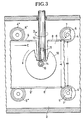
- the substrate carriage is advantageously designed as an essentially rectangular plate, on the upper side of which a plurality of substrate disks are rotatably mounted, the associated axes of rotation each being guided downwards through bearing holes in the substrate carriage and being connected in a rotationally fixed manner to rotor disks which are provided with magnets Waves interact.
- Both the substrate disk and each associated rotor disk are preferably provided with a hub, both of which are connected in a rotationally fixed manner via an axis of rotation, a pair of hubs interacting with a roller bearing, the bearing cage of which is held on the substrate carriage.
- the waves extending transversely to the direction of movement of the substrate carriage are dimensioned such that the magnets firmly connected to them extend approximately from the region of the outer edge of a rotor disk to approximately the disk center.
- the shaft for holding a magnet expediently has a shaft-like recess in the area of the rotor disk, into which one or more permanent magnets are inserted, the permanent magnets being dimensioned such that they fill the shaft-like recess and are otherwise adapted to the rotational contour of the shaft.
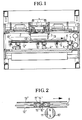
- the device for producing layers with a uniform thickness profile essentially consists of a machine frame 1 holding a coating chamber 2, the coating chamber 2 having an approximately rectangular cross-sectional profile and in the interior of which the sputtering cathode 3 and two parallel rows of bearing blocks 4, 4 ', 4 ⁇ , ... are arranged with rotatably mounted guide rollers 5, 5 ', 5 nav, ... on which the substrate carriage 6 is guided.
- the substrate carriage 6 is in its two mutually parallel longitudinal edges 9, 9 'incorporated V-shaped longitudinal grooves 8, 8' on the rollers 5, 5 ', the upper circumferential edges 7, 7' are rounded, the distance A of the two Longitudinal edges 9, 9 'of the substrate carriage 2 is dimensioned slightly larger than the distance B, which the peripheral edges 7, 7' of two mutually opposite guide rollers 5, 5 'have from each other.
- the movement of the substrate carriage 6 in the direction of arrow C is effected in that the rollers 5, 5 ', 5 ⁇ , ... are driven by electric motors arranged in the bearing blocks 4, 4', 4 ⁇ , ..., the direction of rotation of which Rollers 5, 5 ', ... one row of rollers opposite the direction of rotation of the rollers 5', 5 ′′′ ... the other row of rollers.
- shafts 10, 10 ', 10 ⁇ ... are arranged below the substrate carriage 6 at certain intervals, the axes of rotation of which extend transversely to the direction of movement of the substrate carriage (arrow direction C). These shafts 10, 10 ', ... are driven by an electric motor and run during the coating process in the direction of arrow D u. Since the shafts 10, 10 ', ... are provided with magnets 11 at their free ends reaching below the substrate slide 6, a disk current is generated in the rotor disks 12 mounted on the substrate slide 6, which the rotor disks 12 and the hub en 14, 15 with these rotatably connected substrate disks 13 set in rotation. In the exemplary embodiment shown, the shafts are passed through the wall of the coating chamber 2 in a sealed manner and are driven by electric motors which are fixedly arranged on the outside of the coating chamber (not shown).
- the synchronously rotating rollers 5, 5 ', ... slowly transport the substrate carriage 6 in the direction of the arrow C, the rapidly rotating shafts 10, 10', ... using the permanent magnets 11 arranged thereon, the rotor disks 12, 12 ', ... and also rotate the substrate disks 13, 13', ... with these bearings.
- the device described above has the advantage that practically every batch of a workpiece placed or fastened on the substrate wafer, for example a wafer, is not only moved at a uniform speed in the direction of arrow C through the coating chamber 2 and past the sputtering cathode 3, but also at the same time moved transversely to the direction of passage C, whereby a particularly uniform or rotationally symmetrical layer thickness can also be produced.
- the device works extremely reliably and practically without wear. Lubrication or special maintenance of any parts of the drive is not necessary. Furthermore, the device operates almost noiselessly, since, for example, gear drives or toothed belt drives which produce noise are not present.
- the coating process can finally be followed precisely through inspection windows built into the wall of the coating chamber 2, since the shafts 10, 10 ', ... are attached below the substrate carriage 6, which enables a clear view of the substrates.
Landscapes
- Chemical & Material Sciences (AREA)
- Chemical Kinetics & Catalysis (AREA)
- Engineering & Computer Science (AREA)
- Materials Engineering (AREA)
- Mechanical Engineering (AREA)
- Metallurgy (AREA)
- Organic Chemistry (AREA)
- Physical Vapour Deposition (AREA)
- Manufacturing Of Magnetic Record Carriers (AREA)
Abstract
- 1. Maschinengestell
- 2. Beschichtungskammer
- 3. Zerstäubungskathode
- 4. Lagerbock
- 5. Rolle, Führungsrolle
- 6. Substratschlitten
- 7. umlaufender Rand der Rolle
- 8. Längsnut (V-förmig)
- 9. Längskante
- 10. Welle
- 11. Magnet
- 12. Läuferscheibe
- 13. Substratscheibe
- 14. Nabe
- 15. Nabe
- 16. Drehachse
- 17. Wälzlager
Description
- Die Erfindung betrifft eine Vorrichtung zum Herstellen von Schichten mit gleichmäßigem Dickenprofil auf Substraten durch Kathodenzerstäubung, bestehend aus einer Beschichtungskammer, einer in dieser ortsfest gehaltenen Zerstäubungskathode und einem durch die Beschichtungskammer quer zur Bestäubungskathode bewegbaren, in Schienen und/oder zwischen Gleit- oder Wälzkörpern gehalten und geführten Substratschlitten.
- Es ist eine Vorrichtung bekannt (D E-OS 3306 870), bestehend aus einer Zerstäubungskathode und Substrathaltern auf einem gemeinsamen Fahrgestell, welches unter Ausführung einer kontinuierlichen Drehbewegung der Substrathalter gegenüber der Zerstäubungskathode verfahrbar ist. Am Fahrgestell ist dazu eine Mitnehmerrolle angeordnet, deren Drehachse senkrecht zur Fahrtrichtung verläuft, wobei parallel zur Fahrtrichtung ein Antriebsorgan angeordnet ist, mit dem die Mitnehmerrolle auf einem Teil ihres Weges in Eingriff steht und wobei die Mitnehmerrolle mit einem Substrathalter gekuppelt ist. Das Antriebsorgan ist als Endloskette ausgebildet, die über zwei in Fahrtrichtung hintereinanderliegende Kettenräder geführt ist, die über einen Antriebsmotor in Umlauf versetzbar ist, wobei jede Mitnehmerrolle über ein Kegelrad-Getriebe mit einem Substrathalter zusammenwirkt.
- Diese bekannte Vorrichtung hat unter anderem den Nachteil, außerordentlich aufwendig und voluminös und gleichzeitig wenig betriebssicher zu sein.
- Der vorliegenden Erfindung liegt die Aufgabe zugrunde, eine Vorrichtung des eingangs genannten Typs zu schaffen, die ohne mechanische Getriebe arbeitet, eine besonders flache Bauweise ermöglicht und ohne Wartung auskommt, so daß in keinem Falle ein Öffnen der Beschichtungskammer erforderlich ist.
- Erfindungsgemäß wird dies dadurch erreicht, daß auf dem Substratschlitten auf seiner der Kathode zugewandten Seite ein oder mehrere Substratscheiben drehbar gelagert sind, deren Rotationsachsen jeweils quer zur Bewegungsebene des Substratschlittens angeordnet sind, wobei auf der der Kathode abgewandten Seite des Substratschlittens in der Beschichtungskammer mit Magneten bestückte, motorisch angetriebene Wellen gelagert sind, deren Längsachsen sich in einer zur Bewegungsebene des Substratschlittens parallelen Ebene erstrecken.
- Mit Vorteil ist dazu der Substratschlitten als eine im wesentlichen rechteckige Platte ausgebildet, auf deren Oberseite mehrere Substratscheiben drehbar gelagert sind, wobei die zugehörigen Drehachsen jeweils durch Lagerbohrungen im Substratschlitten nach unten zu hindurchgeführt sind und mit Läuferscheiben drehfest verbunden sind, die mit den mit Magneten versehenen Wellen zusammenwirken.
- Vorzugsweise ist sowohl jede Substratscheibe als auch jede zugehörige Läuferscheibe mit einer Nabe versehen, die beide drehfest über eine Drehachse verbunden sind, wobei jeweils ein Nabenpaar mit einem Wälzlager zusammenwirkt, dessen Lagerkäfig am Substratschlitten gehalten ist.
- Um einen im Drehsinn der Substratscheiben besonders wirksamen Scheibenstrom zu erzeugen, sind die sich quer zur Bewegungsrichtung des Substratschlittens erstreckenden Wellen so bemessen, daß die mit diesen fest verbundenen Magnete sich etwa vom Bereich des äußeren Randes einer Läuferscheibe bis etwa zum Scheibenzentrum erstreckt.
- Zweckmäßigerweise weist die Welle zur Halterung eines Magneten eine schachtartige Aussparung im Bereich der Läuferscheibe auf, in die ein oder mehrere Permanentmagnete eingesetzt sind, wobei die Permanentmagnete so bemessen sind, daß sie die schachtartige Aussparung ausfüllen und im übrigen der Rotationskontur der Welle angepaßt sind.
- Die Erfindung läßt die verschiedensten Ausführungsmöglichkeiten zu; eine davon ist in den anhängenden Zeichnungen schematisch näher dargestellt, und zwar zeigen:
- Fig. 1 eine Beschichtungskammer mit einer an oberen Wandung befestigten Zerstäubungskathode und einem unterhalb der Kathode auf Rollen gelagerten Substratschlitten und mehreren zwischen Substratschlitten und der unteren Wand der Beschichtungskammer drehbar gelagerten Wellen mit an diesen angeordneten Permanentmagneten,
- Fig. 2 einen Teilschnitt des Abschnitts Z des Substratschlittens gemäß Fig. 1 in vergrößerter Darstellung und
- Fig. 3 die Draufsicht auf einen Abschnitt des Substratschlittens in vergrößerter Darstellung
- Die Vorrichtung zum Herstellen von Schichten mit gleichmäßigem Dickenprofil besteht im wesentlichen aus einem eine Beschichtungskammer 2 haltenden Maschinengestell 1, wobei die Beschichtungskammer 2 ein etwa rechteckiges Querschnittsprofil aufweist und in derem Inneren die Zerstäubungskathode 3 und zwei zueinander parallele Reihen von Lagerböcken 4, 4′, 4˝, ... mit auf ihnen drehbar gelagerten Führungsrollen 5, 5′, 5˝, ... angeordnet sind, auf die der Substratschlitten 6 geführt ist. Die beiderseits offene Beschichtungskammer 2 korrespondiert mit zwei Schleusen, die in der Zeichnung nicht näher dargestellt sind und die einerseits das Ein- und Ausfahren des Substratschlittens 6 (in Pfeilrichtung) in bzw. aus der Beschichtungskammer 2 ermöglichen und andererseits das Innere der Beschichtungskammer 2 druckdicht abschließen. Der Substratschlitten 6 liegt mit in seinen beiden zueinander parallelen Längskanten 9, 9′ eingearbeiteten V-förmigen Längsnuten 8, 8′ an den Rollen 5, 5′ an, deren obere umlaufende Ränder 7, 7′ verrundet sind, wobei der Abstand A der beiden Längskanten 9, 9′ des Substratschlittens 2 geringfügig größer bemessen ist als der Abstand B, den die umlaufenden Ränder 7, 7′ zweier einander gegenüberliegender Führungsrollen 5, 5′ voneinander haben. Die Bewegung des Substratschlittens 6 in Pfeilrichtung C wird dadurch bewirkt, daß die Rollen 5, 5′, 5˝, ... über in den Lagerböcken 4, 4′, 4˝, ... angeordnete Elektromotore angetrieben sind, wobei die Drehrichtung der Rollen 5, 5′, ... der einen Rollenreihe entgegengesetzt der Drehrichtung der Rollen 5′, 5‴ ... der anderen Rollenreihe ist.
- Wie Fig. 1 zeigt, sind unterhalb des Substratschlittens 6 in bestimmten Abständen Wellen 10, 10′, 10˝ ... angeordnet, deren Rotationsachsen quer zur Bewegungsrichtung des Substratschlittens (Pfeilrichtung C) verlaufen. Diese Wellen 10, 10′, ... sind elektromotorisch angetrieben und laufen während des Beschichtungsvorgangs in Pfeilrichtung D u. Da die Wellen 10, 10′, ... an ihren freien, bis unter den Substratschlitten 6 reichenden Enden mit Magneten 11 versehen sind, wird in den auf dem Substratschlitten 6 gelagerten Läuferscheiben 12 ein Scheibenstrom erzeugt, der die Läuferscheiben 12 und die über Nab en 14, 15 mit diesen drehfest verbundenen Substratscheiben 13 in Drehung versetzt. Die Wellen sind im dargestellten Ausführungsbeispiel durch die Wand der Beschichtungskammer 2 abgedichtet hindurchgeführt und werden von Elektromotoren angetrieben, die an der Außenseite der Beschichtungskammer (nicht dargestellt) fest angeordnet sind.
- Während des Beschichtungsvorganges transportieren die sich synchron drehenden Rollen 5, 5′, ... den Substratschlitten 6 langsam in Pfeilrichtung C, wobei die rasch rotierenden Wellen 10, 10′, ... mit Hilfe der an diesen angeordneten Permanentmagneten 11 die Läuferscheiben 12, 12′, ... und auch die mit diesen drehfest gelagerten Substratscheiben 13, 13′, ... in Rotation versetzen.
- Die vorstehend beschiebene Vorrichtung hat den Vorteil, daß praktisch jede Partie eines auf der Substratscheibe abgelegten oder befestigten Werkstücks, beispielsweise eines Wafers, nicht nur mit gleichmäßiger Geschwindigkeit in Pfeilrichtung C durch die Beschichtungskammer 2 hindurch und an der Zerstäubungskathode 3 vorbeibewegt wird, sondern sich auch gleichzeitig quer zur Durchlaufrichtung C bewegt, wodurch auch eine besonders gleichmäßige bzw. rotationssymmetrische Schichtdicke herstellbar ist. Die Vorrichtung arbeitet außerordentlich zuverlässig und praktisch verschleißfrei. Eine Schmierung oder besondere Wartung irgendwelcher Teile des Antriebs entfällt. Weiterhin arbeitet die Vorrichtung nahezu geräuschfrei, da beispielsweise Geräusche erzeugende Zahnradgetriebe oder Zahnriemenantriebe nicht vorhanden sind. Der Beschichtungsvorgang läßt sich schließlich durch in die Wand der Beschichtungskammer 2 eingebaute Sichtfenster genau verfolgen, da die Wellen 10, 10′, ... unterhalb des Substratschlittens 6 angebracht sind, womit eine freie Sicht auf die Substrate möglich ist.
Claims (5)
Applications Claiming Priority (2)
| Application Number | Priority Date | Filing Date | Title |
|---|---|---|---|
| DE3725571A DE3725571A1 (de) | 1987-08-01 | 1987-08-01 | Vorrichtung zum herstellen von schichten mit gleichmaessigem dickenprofil auf substraten durch kathodenzerstaeubung |
| DE3725571 | 1987-08-01 |
Publications (3)
| Publication Number | Publication Date |
|---|---|
| EP0302167A2 true EP0302167A2 (de) | 1989-02-08 |
| EP0302167A3 EP0302167A3 (en) | 1990-03-28 |
| EP0302167B1 EP0302167B1 (de) | 1992-05-06 |
Family
ID=6332880
Family Applications (1)
| Application Number | Title | Priority Date | Filing Date |
|---|---|---|---|
| EP88103670A Expired - Lifetime EP0302167B1 (de) | 1987-08-01 | 1988-03-09 | Vorrichtung zum Herstellen von Schichten mit gleichmässigem Dickenprofil auf Substraten durch Kathodenzerstäubung |
Country Status (5)
| Country | Link |
|---|---|
| US (1) | US4793911A (de) |
| EP (1) | EP0302167B1 (de) |
| JP (1) | JPS6455382A (de) |
| KR (1) | KR890003985A (de) |
| DE (2) | DE3725571A1 (de) |
Cited By (1)
| Publication number | Priority date | Publication date | Assignee | Title |
|---|---|---|---|---|
| EP0607786A3 (de) * | 1993-01-19 | 1995-03-22 | Leybold Ag | Vorrichtung zum Beschichten von Substraten. |
Families Citing this family (6)
| Publication number | Priority date | Publication date | Assignee | Title |
|---|---|---|---|---|
| US5130005A (en) * | 1990-10-31 | 1992-07-14 | Materials Research Corporation | Magnetron sputter coating method and apparatus with rotating magnet cathode |
| JPH07508617A (ja) | 1992-06-26 | 1995-09-21 | マティリアルズ リサーチ コーポレイション | ウエハ処理工程ラインのための輸送装置 |
| US5468299A (en) * | 1995-01-09 | 1995-11-21 | Tsai; Charles S. | Device comprising a flat susceptor rotating parallel to a reference surface about a shaft perpendicular to this surface |
| US5795448A (en) * | 1995-12-08 | 1998-08-18 | Sony Corporation | Magnetic device for rotating a substrate |
| US6497799B1 (en) | 2000-04-14 | 2002-12-24 | Seagate Technology Llc | Method and apparatus for sputter deposition of multilayer films |
| US6770146B2 (en) | 2001-02-02 | 2004-08-03 | Mattson Technology, Inc. | Method and system for rotating a semiconductor wafer in processing chambers |
Family Cites Families (8)
| Publication number | Priority date | Publication date | Assignee | Title |
|---|---|---|---|---|
| DE2039416A1 (de) * | 1969-08-11 | 1971-02-25 | Varian Associates | Vakuumgalvanisiervorrichtung |
| US3785853A (en) * | 1972-05-24 | 1974-01-15 | Unicorp Inc | Continuous deposition reactor |
| GB1478464A (en) * | 1973-10-11 | 1977-06-29 | Triplex Safety Glass Co | Reactive sputtering apparatus and supply leads therefor |
| DE2900724C2 (de) * | 1979-01-10 | 1986-05-28 | Siemens AG, 1000 Berlin und 8000 München | Vorrichtung zur Beschichtung von Substraten im Vakuum |
| DE3306870A1 (de) * | 1983-02-26 | 1984-08-30 | Leybold-Heraeus GmbH, 5000 Köln | Vorrichtung zum herstellen von schichten mit rotationssymmetrischem dickenprofil durch katodenzerstaeubung |
| GB8332089D0 (en) * | 1983-12-01 | 1984-01-11 | Atomic Energy Authority Uk | Electrodes |
| US4701251A (en) * | 1986-02-03 | 1987-10-20 | Bvt Limited | Apparatus for sputter coating discs |
| US4808291A (en) * | 1987-09-09 | 1989-02-28 | Denton Vacuum Inc. | Apparatus for coating compact disks |
-
1987
- 1987-08-01 DE DE3725571A patent/DE3725571A1/de not_active Withdrawn
- 1987-11-12 US US07/119,628 patent/US4793911A/en not_active Expired - Fee Related
-
1988
- 1988-03-09 DE DE8888103670T patent/DE3870752D1/de not_active Expired - Fee Related
- 1988-03-09 EP EP88103670A patent/EP0302167B1/de not_active Expired - Lifetime
- 1988-07-06 KR KR1019880008388A patent/KR890003985A/ko not_active Ceased
- 1988-08-01 JP JP63190757A patent/JPS6455382A/ja active Pending
Cited By (1)
| Publication number | Priority date | Publication date | Assignee | Title |
|---|---|---|---|---|
| EP0607786A3 (de) * | 1993-01-19 | 1995-03-22 | Leybold Ag | Vorrichtung zum Beschichten von Substraten. |
Also Published As
| Publication number | Publication date |
|---|---|
| DE3725571A1 (de) | 1989-02-09 |
| DE3870752D1 (de) | 1992-06-11 |
| EP0302167A3 (en) | 1990-03-28 |
| KR890003985A (ko) | 1989-04-19 |
| EP0302167B1 (de) | 1992-05-06 |
| US4793911A (en) | 1988-12-27 |
| JPS6455382A (en) | 1989-03-02 |
Similar Documents
| Publication | Publication Date | Title |
|---|---|---|
| DE3624878C2 (de) | ||
| DE2740807A1 (de) | Bandfoerderer | |
| DE102012104213B4 (de) | Transportsystem für Behandlungsmaschinen sowie Behandlungsmaschine | |
| EP0302167B1 (de) | Vorrichtung zum Herstellen von Schichten mit gleichmässigem Dickenprofil auf Substraten durch Kathodenzerstäubung | |
| DE4341634A1 (de) | Vorrichtung für den Transport von scheibenförmigen Substraten in einer Vakuumbeschichtungsanlage | |
| EP1632444B1 (de) | Vorrichtung zum getakteten Transport von Werkstückträgern | |
| DE3416629C3 (de) | ||
| DE102017116414A1 (de) | Transportvorrichtung zur rotatorischen und/oder linearen bewegung eines werkstücks | |
| DE3805380C2 (de) | Vorrichtung zum Herstellen von Schichten mit gleichmäßigem Dickenprofil auf Substraten durch Kathodenzerstäubung | |
| DE2122990A1 (de) | Vorrichtung zur Bearbeitung der Kanten von Glasscheiben oder dergleichen | |
| DE3436576A1 (de) | Beschickungs- und entnahmevorrichtung, insbesondere an pressen | |
| DE3013082A1 (de) | Etikettierstation einer etikettiermaschine, insbesondere flaschen | |
| DE3784205T2 (de) | Schildanordnung. | |
| DE69219994T2 (de) | Werbetafel mit beweglichen Prismenkörpern | |
| DE2843602C2 (de) | Etikettierstation einer Etikettiermaschine für Gegenstände, insbesondere Flaschen | |
| DE1818688U (de) | Vorrichtung zum transportieren von flachen werkstuecken. | |
| DE3128703C2 (de) | Maschine zum Entgraten der Ränder von Blechen, Platten oder dgl. | |
| DE3811869C2 (de) | ||
| DE69407606T2 (de) | Fördervorrichtung für mechanische teile | |
| DE4131068A1 (de) | Fahrende drehvorrichtungen fuer allseitige oberflaechenbehandlung oder montagen von runden oder anders geformten teilen | |
| DE3040196A1 (de) | Trommel-poliervorrichtung | |
| DE2834620B2 (de) | ||
| DE69107764T2 (de) | Vorrichtung zum zentrieren von röntgenfilmkassetten. | |
| DE2015911A1 (de) | Profilierte Walzen, insbesondere fur Fruchtesortiermaschinen | |
| DE3611494C2 (de) |
Legal Events
| Date | Code | Title | Description |
|---|---|---|---|
| PUAI | Public reference made under article 153(3) epc to a published international application that has entered the european phase |
Free format text: ORIGINAL CODE: 0009012 |
|
| AK | Designated contracting states |
Kind code of ref document: A2 Designated state(s): CH DE FR GB IT LI NL |
|
| 17P | Request for examination filed |
Effective date: 19890119 |
|
| PUAL | Search report despatched |
Free format text: ORIGINAL CODE: 0009013 |
|
| AK | Designated contracting states |
Kind code of ref document: A3 Designated state(s): CH DE FR GB IT LI NL |
|
| RHK1 | Main classification (correction) |
Ipc: C23C 14/50 |
|
| 17Q | First examination report despatched |
Effective date: 19910527 |
|
| GRAA | (expected) grant |
Free format text: ORIGINAL CODE: 0009210 |
|
| PGFP | Annual fee paid to national office [announced via postgrant information from national office to epo] |
Ref country code: FR Payment date: 19920417 Year of fee payment: 6 |
|
| AK | Designated contracting states |
Kind code of ref document: B1 Designated state(s): CH DE FR GB IT LI NL |
|
| ITF | It: translation for a ep patent filed | ||
| REF | Corresponds to: |
Ref document number: 3870752 Country of ref document: DE Date of ref document: 19920611 |
|
| GBT | Gb: translation of ep patent filed (gb section 77(6)(a)/1977) | ||
| ET | Fr: translation filed | ||
| PGFP | Annual fee paid to national office [announced via postgrant information from national office to epo] |
Ref country code: GB Payment date: 19921210 Year of fee payment: 6 |
|
| PGFP | Annual fee paid to national office [announced via postgrant information from national office to epo] |
Ref country code: DE Payment date: 19930222 Year of fee payment: 6 |
|
| PLBE | No opposition filed within time limit |
Free format text: ORIGINAL CODE: 0009261 |
|
| STAA | Information on the status of an ep patent application or granted ep patent |
Free format text: STATUS: NO OPPOSITION FILED WITHIN TIME LIMIT |
|
| PG25 | Lapsed in a contracting state [announced via postgrant information from national office to epo] |
Ref country code: LI Effective date: 19930331 Ref country code: CH Effective date: 19930331 |
|
| PGFP | Annual fee paid to national office [announced via postgrant information from national office to epo] |
Ref country code: NL Payment date: 19930331 Year of fee payment: 6 |
|
| 26N | No opposition filed | ||
| REG | Reference to a national code |
Ref country code: CH Ref legal event code: PL |
|
| PG25 | Lapsed in a contracting state [announced via postgrant information from national office to epo] |
Ref country code: GB Effective date: 19940309 |
|
| PG25 | Lapsed in a contracting state [announced via postgrant information from national office to epo] |
Ref country code: NL Effective date: 19941001 |
|
| GBPC | Gb: european patent ceased through non-payment of renewal fee |
Effective date: 19940309 |
|
| NLV4 | Nl: lapsed or anulled due to non-payment of the annual fee | ||
| PG25 | Lapsed in a contracting state [announced via postgrant information from national office to epo] |
Ref country code: FR Effective date: 19941130 |
|
| PG25 | Lapsed in a contracting state [announced via postgrant information from national office to epo] |
Ref country code: DE Effective date: 19941201 |
|
| REG | Reference to a national code |
Ref country code: FR Ref legal event code: ST |
|
| PG25 | Lapsed in a contracting state [announced via postgrant information from national office to epo] |
Ref country code: IT Free format text: LAPSE BECAUSE OF NON-PAYMENT OF DUE FEES;WARNING: LAPSES OF ITALIAN PATENTS WITH EFFECTIVE DATE BEFORE 2007 MAY HAVE OCCURRED AT ANY TIME BEFORE 2007. THE CORRECT EFFECTIVE DATE MAY BE DIFFERENT FROM THE ONE RECORDED. Effective date: 20050309 |