EP0300792A2 - Kontroll-Einrichtungen für automatischen Gangwechsel - Google Patents
Kontroll-Einrichtungen für automatischen Gangwechsel Download PDFInfo
- Publication number
- EP0300792A2 EP0300792A2 EP88306708A EP88306708A EP0300792A2 EP 0300792 A2 EP0300792 A2 EP 0300792A2 EP 88306708 A EP88306708 A EP 88306708A EP 88306708 A EP88306708 A EP 88306708A EP 0300792 A2 EP0300792 A2 EP 0300792A2
- Authority
- EP
- European Patent Office
- Prior art keywords
- gear
- speed range
- control means
- transmitting torque
- disk clutch
- Prior art date
- Legal status (The legal status is an assumption and is not a legal conclusion. Google has not performed a legal analysis and makes no representation as to the accuracy of the status listed.)
- Granted
Links
- 230000008859 change Effects 0.000 title claims description 83
- 230000005540 biological transmission Effects 0.000 claims abstract description 81
- 239000012530 fluid Substances 0.000 claims description 13
- 230000007935 neutral effect Effects 0.000 claims description 9
- 230000009471 action Effects 0.000 claims description 2
- 239000004576 sand Substances 0.000 claims 1
- 230000000994 depressogenic effect Effects 0.000 abstract description 9
- 230000009467 reduction Effects 0.000 abstract description 8
- 238000001514 detection method Methods 0.000 description 17
- 244000144983 clutch Species 0.000 description 15
- 230000007423 decrease Effects 0.000 description 5
- 230000001133 acceleration Effects 0.000 description 4
- 238000010586 diagram Methods 0.000 description 4
- 238000000034 method Methods 0.000 description 4
- 230000004075 alteration Effects 0.000 description 2
- 230000003247 decreasing effect Effects 0.000 description 2
- 230000003292 diminished effect Effects 0.000 description 2
- 230000006870 function Effects 0.000 description 2
- 230000007246 mechanism Effects 0.000 description 2
- 230000004048 modification Effects 0.000 description 2
- 238000012986 modification Methods 0.000 description 2
- 230000008569 process Effects 0.000 description 2
- 230000002441 reversible effect Effects 0.000 description 2
- 230000000903 blocking effect Effects 0.000 description 1
- 239000013256 coordination polymer Substances 0.000 description 1
- 239000000446 fuel Substances 0.000 description 1
- XDDAORKBJWWYJS-UHFFFAOYSA-N glyphosate Chemical compound OC(=O)CNCP(O)(O)=O XDDAORKBJWWYJS-UHFFFAOYSA-N 0.000 description 1
- 239000000203 mixture Substances 0.000 description 1
- 230000002093 peripheral effect Effects 0.000 description 1
- 238000004904 shortening Methods 0.000 description 1
- 230000002311 subsequent effect Effects 0.000 description 1
- 230000001360 synchronised effect Effects 0.000 description 1
Images


Classifications
-
- F—MECHANICAL ENGINEERING; LIGHTING; HEATING; WEAPONS; BLASTING
- F16—ENGINEERING ELEMENTS AND UNITS; GENERAL MEASURES FOR PRODUCING AND MAINTAINING EFFECTIVE FUNCTIONING OF MACHINES OR INSTALLATIONS; THERMAL INSULATION IN GENERAL
- F16H—GEARING
- F16H61/00—Control functions within control units of change-speed- or reversing-gearings for conveying rotary motion ; Control of exclusively fluid gearing, friction gearing, gearings with endless flexible members or other particular types of gearing
- F16H61/04—Smoothing ratio shift
- F16H61/0403—Synchronisation before shifting
-
- B—PERFORMING OPERATIONS; TRANSPORTING
- B60—VEHICLES IN GENERAL
- B60W—CONJOINT CONTROL OF VEHICLE SUB-UNITS OF DIFFERENT TYPE OR DIFFERENT FUNCTION; CONTROL SYSTEMS SPECIALLY ADAPTED FOR HYBRID VEHICLES; ROAD VEHICLE DRIVE CONTROL SYSTEMS FOR PURPOSES NOT RELATED TO THE CONTROL OF A PARTICULAR SUB-UNIT
- B60W10/00—Conjoint control of vehicle sub-units of different type or different function
- B60W10/02—Conjoint control of vehicle sub-units of different type or different function including control of driveline clutches
-
- B—PERFORMING OPERATIONS; TRANSPORTING
- B60—VEHICLES IN GENERAL
- B60W—CONJOINT CONTROL OF VEHICLE SUB-UNITS OF DIFFERENT TYPE OR DIFFERENT FUNCTION; CONTROL SYSTEMS SPECIALLY ADAPTED FOR HYBRID VEHICLES; ROAD VEHICLE DRIVE CONTROL SYSTEMS FOR PURPOSES NOT RELATED TO THE CONTROL OF A PARTICULAR SUB-UNIT
- B60W10/00—Conjoint control of vehicle sub-units of different type or different function
- B60W10/04—Conjoint control of vehicle sub-units of different type or different function including control of propulsion units
- B60W10/06—Conjoint control of vehicle sub-units of different type or different function including control of propulsion units including control of combustion engines
-
- B—PERFORMING OPERATIONS; TRANSPORTING
- B60—VEHICLES IN GENERAL
- B60W—CONJOINT CONTROL OF VEHICLE SUB-UNITS OF DIFFERENT TYPE OR DIFFERENT FUNCTION; CONTROL SYSTEMS SPECIALLY ADAPTED FOR HYBRID VEHICLES; ROAD VEHICLE DRIVE CONTROL SYSTEMS FOR PURPOSES NOT RELATED TO THE CONTROL OF A PARTICULAR SUB-UNIT
- B60W10/00—Conjoint control of vehicle sub-units of different type or different function
- B60W10/10—Conjoint control of vehicle sub-units of different type or different function including control of change-speed gearings
- B60W10/11—Stepped gearings
-
- B—PERFORMING OPERATIONS; TRANSPORTING
- B60—VEHICLES IN GENERAL
- B60W—CONJOINT CONTROL OF VEHICLE SUB-UNITS OF DIFFERENT TYPE OR DIFFERENT FUNCTION; CONTROL SYSTEMS SPECIALLY ADAPTED FOR HYBRID VEHICLES; ROAD VEHICLE DRIVE CONTROL SYSTEMS FOR PURPOSES NOT RELATED TO THE CONTROL OF A PARTICULAR SUB-UNIT
- B60W30/00—Purposes of road vehicle drive control systems not related to the control of a particular sub-unit, e.g. of systems using conjoint control of vehicle sub-units
- B60W30/18—Propelling the vehicle
- B60W30/19—Improvement of gear change, e.g. by synchronisation or smoothing gear shift
-
- F—MECHANICAL ENGINEERING; LIGHTING; HEATING; WEAPONS; BLASTING
- F16—ENGINEERING ELEMENTS AND UNITS; GENERAL MEASURES FOR PRODUCING AND MAINTAINING EFFECTIVE FUNCTIONING OF MACHINES OR INSTALLATIONS; THERMAL INSULATION IN GENERAL
- F16H—GEARING
- F16H3/00—Toothed gearings for conveying rotary motion with variable gear ratio or for reversing rotary motion
- F16H3/02—Toothed gearings for conveying rotary motion with variable gear ratio or for reversing rotary motion without gears having orbital motion
- F16H3/08—Toothed gearings for conveying rotary motion with variable gear ratio or for reversing rotary motion without gears having orbital motion exclusively or essentially with continuously meshing gears, that can be disengaged from their shafts
- F16H3/12—Toothed gearings for conveying rotary motion with variable gear ratio or for reversing rotary motion without gears having orbital motion exclusively or essentially with continuously meshing gears, that can be disengaged from their shafts with means for synchronisation not incorporated in the clutches
-
- B—PERFORMING OPERATIONS; TRANSPORTING
- B60—VEHICLES IN GENERAL
- B60W—CONJOINT CONTROL OF VEHICLE SUB-UNITS OF DIFFERENT TYPE OR DIFFERENT FUNCTION; CONTROL SYSTEMS SPECIALLY ADAPTED FOR HYBRID VEHICLES; ROAD VEHICLE DRIVE CONTROL SYSTEMS FOR PURPOSES NOT RELATED TO THE CONTROL OF A PARTICULAR SUB-UNIT
- B60W2710/00—Output or target parameters relating to a particular sub-units
- B60W2710/06—Combustion engines, Gas turbines
- B60W2710/0644—Engine speed
-
- F—MECHANICAL ENGINEERING; LIGHTING; HEATING; WEAPONS; BLASTING
- F16—ENGINEERING ELEMENTS AND UNITS; GENERAL MEASURES FOR PRODUCING AND MAINTAINING EFFECTIVE FUNCTIONING OF MACHINES OR INSTALLATIONS; THERMAL INSULATION IN GENERAL
- F16H—GEARING
- F16H61/00—Control functions within control units of change-speed- or reversing-gearings for conveying rotary motion ; Control of exclusively fluid gearing, friction gearing, gearings with endless flexible members or other particular types of gearing
- F16H61/04—Smoothing ratio shift
- F16H61/0403—Synchronisation before shifting
- F16H2061/0407—Synchronisation before shifting by control of clutch in parallel torque path
-
- F—MECHANICAL ENGINEERING; LIGHTING; HEATING; WEAPONS; BLASTING
- F16—ENGINEERING ELEMENTS AND UNITS; GENERAL MEASURES FOR PRODUCING AND MAINTAINING EFFECTIVE FUNCTIONING OF MACHINES OR INSTALLATIONS; THERMAL INSULATION IN GENERAL
- F16H—GEARING
- F16H61/00—Control functions within control units of change-speed- or reversing-gearings for conveying rotary motion ; Control of exclusively fluid gearing, friction gearing, gearings with endless flexible members or other particular types of gearing
- F16H61/04—Smoothing ratio shift
- F16H2061/0425—Bridging torque interruption
-
- Y—GENERAL TAGGING OF NEW TECHNOLOGICAL DEVELOPMENTS; GENERAL TAGGING OF CROSS-SECTIONAL TECHNOLOGIES SPANNING OVER SEVERAL SECTIONS OF THE IPC; TECHNICAL SUBJECTS COVERED BY FORMER USPC CROSS-REFERENCE ART COLLECTIONS [XRACs] AND DIGESTS
- Y10—TECHNICAL SUBJECTS COVERED BY FORMER USPC
- Y10T—TECHNICAL SUBJECTS COVERED BY FORMER US CLASSIFICATION
- Y10T74/00—Machine element or mechanism
- Y10T74/19—Gearing
- Y10T74/19219—Interchangeably locked
- Y10T74/19228—Multiple concentric clutch shafts
-
- Y—GENERAL TAGGING OF NEW TECHNOLOGICAL DEVELOPMENTS; GENERAL TAGGING OF CROSS-SECTIONAL TECHNOLOGIES SPANNING OVER SEVERAL SECTIONS OF THE IPC; TECHNICAL SUBJECTS COVERED BY FORMER USPC CROSS-REFERENCE ART COLLECTIONS [XRACs] AND DIGESTS
- Y10—TECHNICAL SUBJECTS COVERED BY FORMER USPC
- Y10T—TECHNICAL SUBJECTS COVERED BY FORMER US CLASSIFICATION
- Y10T74/00—Machine element or mechanism
- Y10T74/19—Gearing
- Y10T74/19219—Interchangeably locked
- Y10T74/19251—Control mechanism
- Y10T74/19256—Automatic
- Y10T74/1926—Speed responsive
Definitions
- the present invention relates to an automatic change gear control means for controlling the gear-shifting operation of an automatic transmission of a type which employs a synchromesh type transmission.
- Japanese Patent Laid-Open No. 60-11764 discloses a control method for an automatic transmission. This method involves a double clutch operation in which a synchronizing load is detected during gear-shifting, and in which, when the load is too large with respect to the capacity of a synchronizing device, a clutch which has been disconnected so as to enable the gear to be shifted is once again engaged before the synchronization is performed, i.e., before gears are shifted, the clutch is then again disengaged, and synchronization is then performed. In this way, the synchronizing load is reduced before the synchronization operation is performed, and the time required for gear-shifting is therefore reduced while any asynchronization is prevented.
- the present inventor has proposed an automatic change gear control means in which an electromagnetic multiple-disk clutch is mounted on a highest gear, i.e., on a 5th gear so that it is operated when gears are shifted up so as to enable the gears to be smoothly shifted up without disengaging the clutch, and filed this patent application under Japanese Patent Laid-Open No. 63-26452 (Patent Application No. 61-166672).
- this automatic change gear control means is applied only to the up-shift of gears, and still suffers from a problem involving time lag when gears are shifted down.
- the present inventor improved the automatic change gear control means disclosed in Japanese Patent Laid-Open No. 63-26452, and developed an automatic change gear control means in which electromagnetic multiple-disk clutches are respectively mounted on the lowest speed gear, i.e., the 1st speed gear, and the highest speed gear, i.e., the 5th speed gear, and torque varying means (electromagnetic or hydraulic multiple-disk clutches) is operated when the gears are shifted either down or up so as to enable the up-shift or down-shift operation to be smoothly conducted without disengaging the clutch.
- electromagnetic multiple-disk clutches are respectively mounted on the lowest speed gear, i.e., the 1st speed gear
- the highest speed gear i.e., the 5th speed gear
- torque varying means electromagtic or hydraulic multiple-disk clutches
- gear-shifting operations be performed quickest when a vehicle is operated at maximum acceleration after it has been started, in particular, when gears are shifted up from 1st gear to 2nd gear and when the vehicle is accelerated from a coasting state (running by force of inertia in a neutral state), e.g., when the vehicle is operated at full acceleration in 1st gear after the gears have been shifted down from 2nd to 1st.
- a coasting state running by force of inertia in a neutral state
- the above-described automatic change gear control means has a disadvantage in that it requires four operation steps when the gears are shifted up or down between 1st gear and 2nd gear.
- the four up-shift steps comprise disengaging the electromagnetic multiple-disk clutch mounted on 1st gear, gradually engaging the electromagnetic multiple-disk clutch mounted on 5th gear, synchronizing the r.p.m. of an input shaft to that of 2nd gear, and shifting to 2nd gear.
- the four down-shift steps comprise gradually engaging the electromagnetic multiple-disk clutch mounted on 5th speed gear, disengaging 2nd gear, disengaging the electromagnetic multiple-disk clutch mounted on 5th gear, and engaging the electromagnetic multiple-disk clutch mounted on 1st gear.
- an automatic change gear control means incorporating a one-way clutch in a gear train thereof has been developed.
- a primary object of the present invention is to provide an automatic change gear control means for a synchromesh type automatic transmission which enables up-shift and down-shift to be performed in a state where a clutch is engaged so as to perform up-shift and down-shift operations smoothly, and which is therefore capable of shortening the time required for gear-shifting and preventing non-transmission of torque from occurring during gear-shifting operation which would otherwise make the driver feel a time lag caused by gear-shifting.
- Another object of the present invention is to provide an automatic change gear control means having a control means which has a transmitting torque varying means in a highest speed gear, and in which, when gears are shifted up, torque is loaded to the transmitting torque varying means, the amount of torque loaded to the transmit ting torque varying means being gradually increased, and the torque loaded to the transmitting torque varying means being released after gear have been shifted up.
- Another object of the present invention is to provide an automatic change gear control means having a control means in which transmitting torque varying means are respectively provided in a highest speed gear and a lowest speed gear, and in which, when gears are shifted down, a currently engaged gear is disengaged after the transmitting torque varying means mounted on the highest speed gear has been actuated, the transmitting torque varying means mounted on the lowest speed gear is actuated, the amount of torque loaded thereto is gradually increased, gears are shifted down, and the torque loaded to the transmitting torque varying means is released after gears have been shifted down.
- Another object of the present invention is to provide an automatic change gear control means including a transmitting torque varying means which comprises a friction clutch that can vary a torque transmitted and that may be an electromagnetic multiple-disk clutch or fluid clutch, the amount of torque loaded to the transmitting torque varying means being varied for each gear combination, and the amount of torque loaded to the electromagnetic multiple-disk clutch being controlled by the amount of current that is caused to flow in an actuator thereof, whereas the amount of torque loaded to the fluid clutch being varied by the amount of oil pressure supplied to an actuator.
- a transmitting torque varying means which comprises a friction clutch that can vary a torque transmitted and that may be an electromagnetic multiple-disk clutch or fluid clutch, the amount of torque loaded to the transmitting torque varying means being varied for each gear combination, and the amount of torque loaded to the electromagnetic multiple-disk clutch being controlled by the amount of current that is caused to flow in an actuator thereof, whereas the amount of torque loaded to the fluid clutch being varied by the amount of oil pressure supplied to an actuator.
- Another object of the present invention is to provide an automatic change gear control means for a synchromesh type automatic transmission which is capable of performing gear up-shift and down-shift operations without disengaging a clutch so as to enable the time needed to engage and disengage the clutch to be reduced, which enables a time lag caused by gear-shifting to be prevented because of the clutch being not disengaged, which enables non-transmission of torque to be prevented from occurring when gears are shifted up or down, which enables impact caused by engagement of the clutch to be eliminated, and which ensures smooth gear-shifting which does not make a driver feel as if a vehicle is losing power or speed.
- Another object of the present invention is to provide an automatic change gear control means which has the same structure as that of a known synchromesh automatic transmission except that the synchronizing devices mounted on the highest speed gear and the 1st gear in the known automatic transmission are replaced by transmitting torque varying means such as electromagnetic multiple-disk clutches, and which therefore enables another parts to be used in common.
- Another object of the present invention is to provide an automatic change gear control means in which transmitting torque varying means such as electromagnetic multiple-disk clutches or fluid multiple-disk clutches are respectively provided in a highest speed gear and a 2nd gear, in which, when gears are shifted up between the highest speed gear and the 2nd gear, the transmitting torque varying means mounted on the highest speed gear is actuated, and in which, when gears are shifted down, a currently engaged gear is disengaged after the transmitting torque varying means mounted on the highest speed gear has been actuated, the transmitting torque varying means mounted on the 2nd gear is actuated, and gear shift down is then performed.
- transmitting torque varying means such as electromagnetic multiple-disk clutches or fluid multiple-disk clutches
- Another object of the present invention is to provide an automatic change gear control means which has the same structure as that of a known synchromesh type automatic transmission except that a one-way clutch is mounted on a 1st gear train for a 1st speed range so as to enable gears to be shifted between the 1st gear and a 2nd gear smoothly and in a short period of time, that is, so as to enable shifting between the 1st gear and the 2nd gear to be performed only by engaging or disengaging a transmitting torque varying means mounted on the 2nd gear such as an electromagnetic multiple-disk clutch and thereby enable a gear-shifting operation to be performed smoothly and in a short period of time when a vehicle is operated at maximum acceleration after it has started, e.g., when gears are shifted up from the 1st gear to the 2nd gear or when the vehicle is accelerated at maximum power from a coasting state, e.g., when the vehicle is accelerated in the 1st gear after the gears have been shifted down from the 2nd gear to
- Another object of the present invention is to provide an automatic change gear control means in which a vehicle is driven in a 1st speed range by a one-way clutch, and is therefore driven only while an accelerating pedal is being depressed and not driven while the accelerating pedal is not being depressed so as to enable jolting of the vehicle which occurs when the accelerating pedal is depressed and released to be diminished, in which gear up-shift and down-shift is conducted without disengaging a clutch in a synchromesh type automatic transmission so as to enable the time needed to engage and disengage the clutch to be shortened, which enables non-transmission of torque to be prevented from occurring when gears are shifted up or down owing to the clutch not being disengaged, which enables impact caused by engagement of the clutch to be eliminated, and which ensures smooth gear-shifting which does not make a drive feel as if a vehicle is losing power or speed.
- Another object of the present invention is to provide an automatic change gear control means which has the same structure as that of a known synchromesh type automatic transmission except that the synchronizing devices mounted on a highest speed gear and a 2nd gear are replaced by transmitting torque varying means such as electro magnetic multiple-disk clutches and that a one-way clutch is provided in a 1st gear, and which therefore enables another parts to be used in common.
- FIG. 1 is a block diagram of a control system of an automatic change gear control means according to the present invention
- a control system is subsequently the same as, for example, that employed in the automatic change gear control means which has been disclosed in Japanese Patent Laid-Open No.
- the former incorporates electromagnetic multiple-disk clutches and a control circuit for controlling the multiple-disk clutches, the multiple-disk clutches being provided in a highest speed gear ratio speed range which is the final speed range of a synchromesh type transmission which is to be described later (hereinafter referred to as a highest speed gear or a 5th gear) and in a lowest speed gear ratio speed range which is the final speed range (hereinafter referred to as a lowest speed gear or a 1st gear).
- an engine 1 includes a throttle valve for controlling the amount of sucked gas (air or air-fuel mixture).
- a fly-wheel 27 is mounted on an output shaft of the engine 1.
- a clutch 2 which may be a friction clutch is disengaged by a release lever 28 which is moved back and forth by a piston rod 29 actuated by an actuator 3 of the clutch 2, that is, the engagement and disengagement of the clutch 2 is controlled by the actuator 3 which outputs a clutch signal CP.
- the clutch actuator 3 is controlled by a hydraulic device 4.
- a transmission actuator 5 includes an actuator 13 for actuating an electromagnetic multiple-disk clutch C1 and an actuator 15 for actuating an electromagnetic multiple-disk clutch C5, and outputs clutch signals EC1 and EC5.
- a synchromesh type transmission 6 includes gear trains which are changed by the drive of the actuator 5.
- the transmission also includes an input shaft 8 connected to the clutch 2, an output shaft 19 disposed in parallel to the input shaft 8, and a gear position sensor 30 for detecting the position of a currently engaged speed gear.
- a select lever 7 is operated by a driver so as to select "N" range (neutral position), "D” range (automatic change gear position), "1" range (1st speed position), “2" range (2nd speed position), “3” range (3rd speed position), or “R” range (reverse position) by positioning a lever to a corresponding position.
- a select signal SP which represents a selected range is output by a select sensor 31.
- a rotation sensor 32 is adapted to detect the rotational speed of the input shaft 8 and output a input rotational speed signal IP.
- a vehicle speed sensor 33 detects a vehicle speed from the rotational speed of the output shaft 19, and outputs an output rotational speed signal WP.
- An engine speed sensor 10 detects the speed of the engine 1 by detecting the rotational speed of the fly-wheel 27, and outputs an engine speed signal RP.
- An electronic control device 9 which is a microcomputer comprises a processor 34 for interpreting and executing instructions in a computer, i.e., for processing operations, a read-only memory or ROM 35 for storing a control program used to control the transmission 6 and the actuator 3 of the clutch 2, an output port 36, an input port 37, a random-access memory, RAM 38 for storing the operation results, and an address bus, that is, BUS 39 for connecting these components.
- the output port 36 is connected to the clutch actuator 3, the hydraulic device 4, the transmission actuator 5, the actuator 13 for the electromagnetic multiple-disk clutch C1, and the actuator 15 for the electromagnetic multiple-disk clutch C5, and outputs drive signals CDV, PDV, ADV, CBV, and CAV for respectively driving these components.
- the input port 37 receives a detection signal AP from an accelerator pedal 11 and a detection signal BP from a brake pedal 12, in addition to those from the aforementioned sensors 10, 30, 31, 32, and 33.
- the accelerator pedal 11 has an acceleration sensor 40 which may be a potentiometer for detecting the depression of the accelerator pedal 11.
- the brake pedal 12 has a brake sensor 41 for detecting the depression of the brake pedal 12.
- Fig. 5 is cross-sectional view of the essential parts of the synchromesh type transmission 6.
- the transmission 6 is an assembly of a plurality of gear trains having a different number of teeth which are disposed in series between the parallel disposed input shaft 8 and the output shaft 19, and which includes a 1st speed gear train 1M, a 2nd speed gear train 2M, a 3rd speed gear train 3M, a 4th speed gear train 4M, and a 5th speed gear train 5M.
- the gear trains are of a constant mesh type, and are therefore mounted in such a manner that one of the gears in each gear train is fixed in the rotational direction with respect to the input shaft 8 or the output shaft 19 while other gear is rotated relative to the input shaft 8 or the output shaft 9.
- the input shaft 8 is mounted on a disk of the clutch 2 which may be a friction clutch in such a manner as to be rotatable together with the clutch disk.
- a known synchronizing device D2 is mounted on the 2nd speed gear train 2M, and synchronizing devices D3 and D4 are mounted on the 3rd speed gear train 3M and the 4th speed gear train 4M, respectively.
- the electromagnetic multiple-disk clutch C1 is mounted on the 1st speed gear train 1M which represents the lowest speed range, and the electromagnetic multiple-disk clutch C5 is provided on the 5th speed gear train 5M which represents the highest speed range.
- the actuators 13 and 15 for actuating the electromagnetic multiple-disk clutches C1 and C5 are also provided.
- Fig. 6 shows in an enlarged scale the portion of the transmission on which the electromagnetic multiple-disk clutch C1 or C5 is mounted.
- output disks 20 mounted on part of the 1st speed gear train 1M or the 5th speed gear train 5M are brought into frictional contact with inner disks 21 mounted on the output shaft 19 by an electromagnetic attracting action that takes place between a coil 22 and an armature 23 which together constitute the actuator 13 or 15 for the electromagnetic multiple-disk clutch C1 or C5, by which torque transmission is conducted.
- Amount of torque transmitted by the electromagnetic multiple-disk clutch C1 or C5 increases or decreases in proportion to the amount of current CB or CA that flows through the coil 22, as shown in Fig. 7.
- the current CB or CA is caused to flow in the actuator 13 or 15 by the signal CBV or CAV from the processor 34 so as to increase or decrease of the torque transmitted by the multiple-disk clutch C1 or C5 or to start or end the torque transmission.
- the actuator 15 for the electromagnetic multiple-disk C5 is energized by the signal CAV.
- the amount of current CA gradually increases, the amount of torque transmitted through the 5th speed gear train 5M increases owing to the relationship between the reduction ratios SR of the 5th speed gear train and the gear train 2M, the gear train 3M or the 4th speed gear train, and the gear engaging load on the synchronizing device D2, D3 or D4 is therefore reduced, making the corresponding gear train loosely engaged.
- the transmission actuaktor drive signal ADV is generated from the processor 34 so as to move a sleeve of the synchronizing device D2, D3 or D4, disengage the currently engaged gear train, and thereby make the transmission neutral.
- the rotational speed of the input shaft 8 decreases owing to a small reduction gear ratio of the 5th speed gear train 5M.
- the processor 34 again generates a transmission actuator drive signal ADV so as to smoothly engage a subsequent speed gear train.
- the processor 34 reads the selection signal through the BUS 39, stores it in the RAM 38, and outputs the drive signal ADV from the output port 36 to the actuator 5 of the transmission 6 so as to drive the actuator 5 and thereby shift the transmission 6 to a 1st gear.
- the processor 34 receives a gear position signal GP from the gear position sensor 30, thereby detects that the transmission 6 has been actually shifted to 1st gear, and stores the received signal in the RAM 38 as a TCS.
- the processor 34 outputs a clutch drive signal CDV to the actuator 3 for the clutch 2 through the output port 36 in order to have the position rod 29 gradually moved leftward by the actuator 3 and thereby move the release lever 28 gradually in the leftward direction.
- torque to be transmitted by the clutch 2 varies, as shown by a symbol indicated by "a” in the graph of Fig. 3, and the clutch 2 becomes engaged after passing through a semiengaged state so as to cause the vehicle to start moving.
- a symbol “b” in Fig. 3 denotes a case where the clutch 2 which has been engaged becomes disengaged after passing through a semiengaged state.
- the processor 34 cyclically receives a detection signal (a detection pulse) from the vehicle speed sensor 33 through the input port 37, calculates the vehicle speed V, and stores the result in the RAM 38 as V.
- the processor 34 also receives a detection signal, i.e., a depression AP, in respect of the accelerating pedal 11 from the sensor 40 through the input port 37, stores it in the RAM 38 as AP, and obtains a gear to be shifted to from a shift map SM which is stored in the ROM 35 as part of the program thereof and which corresponds to vehicle speed SP and depression AP.
- the ROM 35 stores a position signal CLT in respect of the actuator 3 for the clutch 2, reduction ratios SR of the respective gear trains, and a rotational speed tolerance ⁇ N of the input shaft 8, in addition to the shift map SM such as that shown in Fig. 2 which corresponds to vehicle speed SP and depression AP.
- symbols I (1), II (2), III (3), IV (4), and V (5) respectively designate the 1st speed range, the 2nd speed range, the 3rd speed range, the 4th speed range, and the 5th speed range.
- the solid lines in the figure denote boundaries of the speed ranges which are used when gears are shifted up, and the dotted lines designate boundaries of the speed ranges which are used when gears are shifted down.
- a subsequent speed gear TCI can be obtained from the depression AP and the vehicle speed SP.
- the processor 34 compares the currently selected gear TCS which is stored in the RAM 38 with the obtained gear, and, if they are the same, proceeds to a subsequent processing without generating the drive signal ADV. If they are not the same, it is determined whether or not gears should be shifted up or down. If gears must be shifted up, the operation process in the flowchart of Fig. 4 (A) which will be described later is executed in order to change gear to the required gear. In a case of shift-down, the process in the flowchart of Fig. 4 (B) which will be described later is executed.
- the processor 34 receives a gear shift-up instruction, it outputs an electromagnetic multiple-disk clutch drive signal CAV to the actuator 15 of the clutch C5 through the output port 36, by which a gradually increasing current CA is supplied to the actuator 15 of the electromagnetic multiple- disk clutch C5 which is mounted on the highest speed gear, i.e, the 5th speed gear, of the synchromesh type transmission 6.
- a gradually increasing current CA is supplied to the actuator 15 of the electromagnetic multiple- disk clutch C5 which is mounted on the highest speed gear, i.e, the 5th speed gear, of the synchromesh type transmission 6.
- DCA the amount of current supplied to the actuator 15 gradually increases
- TP transmitted through the electromagnetic multiple-disk clutch C5
- data representing the increasing torque TP is stored in the RAM 38 of the processor 34 through the input port 37.
- the processor 34 determines that the torque TP transmitted by the electromagnetic multiple-disk clutch C5 has reached a predetermined value and that the load applied to the currently engaged gear train has therefore become smaller than a predetermined value stored in the ROM 35, it outputs a drive signal ADV to a shifting actuator within the actuator 5 of the transmission 6 through the output port 36 so as to disengage the currently engaged gear train.
- the processor 34 detects from a gear position signal GP of the gear position sensor 30 that the detection signal has been turned on, and thereby detects that the transmission 6 has been placed in neutral.
- the processor 34 reads a subsequent speed gear TCI from the RAM 38, reads from the ROM 35 the reduction gear ratio i of the subsequent speed change gear and the reduction gear ratio i f of the final speed change gear, and performs the following calculation using the gear ratios as well as the vehicle speed V in the RAM 38 so as to obtain an optimum engine speed N1 needed to change gears to the subsequent speed change gear TCI: where R represents the radius of a tyre.
- the thus-obtained optimum engine speed N1 is stored in the RAM 38.
- the amount of current CA supplied to the actuator 15 of the electromagnetic multiple-disk clutch C5 is now gradually increasing. Therefore, the torque transmitted by the clutch C5, i.e., the torque loaded thereto, increases, and the speed of the engine 1, i.e., the rotational speed N0 of the input shaft 8, decreases.
- the processor 34 receives through the input port 37 a detection pulse IP from the rotation sensor 32, calculates the rotational speed N0 of the input shaft 8 from the detection pulse IP, and stores the result in the RAM 38.
- the processor 34 If it has been determined that N ⁇ ⁇ N, i.e., that N0 - N1 ⁇ ⁇ N, the processor 34 outputs again the drive signal ADV to the transmission actuator 5 through the output port 36, by which means the synchronizing device D2, D3 or D4 of the transmission 6 is driven through a suitable hydraulic circuit so as to enable gears to be shifted up to the subsequent speed gear.
- the processor 34 recognizes a detection signal from the gear position detection signal GP which is input through the input port 37 from the gear position sensor 30 and hence that a gear-shift has taken place. At the same time, the processor 34 outputs a signal through the output port 36 so as to break off the electromagnetic multiple-disk clutch drive current, i.e., to reduce CA to zero. In consequence, load applied to the electromagnetic multiple-disk clutch C5, i.e., the torque applied thereto, is released.
- Down-shift operation is substantially the same as the up-shift operation, and is performed as follows:
- the processor 34 recognizes a gear shift-down instruction, it outputs an electromagnetic multiple-disk clutch drive signal CAV to the actuator 15 of the clutch C5 through the output port 36, by which a gradually increasing current CA is supplied to the actuator 15.
- a gradually increasing current CA is supplied to the actuator 15.
- the amount of current supplied to the actuator 15 gradually increases (DCA)
- the amount of torque (TP) transmitted through the electromagnetic multiple-disk clutch C5 increases, and data representing the increasing torque TP is stored in the RAM 38 of the processor 34 through the input port 37.
- the processor 34 determines that the torque TP transmitted by the electromagnetic multiple-disk clutch C5 has reached a predetermined value and that the load applied to the currently engaged gear train has therefore become smaller than a predetermined value stored in the ROM 35, it outputs a drive signal ADV to a shifting actuator within the actuator 5 of the transmission 6 through the output port 36 so as to disengage the currently engaged gear train.
- the processor 34 detects from a gear position signal GP of the gear position sensor 30 that the detection signal has been turned on, and thus disengages the synchronizing device D2, D3 or D4 without disengaging the clutch 2 in a state where the actuator 15 for the clutch C5 is energized. Subsequently, the processor 34 detects that the transmission 6 has become neutral. The processor then de-energizes the actuator 15 and thereby reduces the current CA supplied thereto to zero. Next, the processor 34 energizes the electromagnetic multiple-disk clutch C1 mounted on the lowest speed gear, i.e., the 1st gear train 1M, and thereby causes current CB to flow therein so as to increase the rotational speed N0 of the input shaft 8.
- the processor 34 reads a subsequent gear TCI from the RAM 38, reads from the ROM 35 the reduction gear ratio i of the subsequent speed change gear and the reduction gear ratio i f of the final speed change gear (the 1st speed gear), and performs the following calculation using the gear ratios as well as the vehicle speed V in the RAM 38 so as to obtain an optimum engine speed N1 needed to change gears to the subsequent gear TCI: where R represents the radius of a tyre.
- the thus-obtained optimum engine speed N1 is stored in the RAM 38.
- the amount of current CB supplied to the electromagnetic multiple-disk clutch C1 is non-gradually increasing (as increments of current DCB). Therefore, the torque transmitted by the clutch C1, i.e., the torque loaded thereto, increases, and the speed of the engine 1, i.e., the rotational speed N0 of the input shaft 8, thereby increases.
- the processor 34 receives through the input port 37 a detection pulse IP from the rotation sensor 32, calculates a rotational speed N0 of the input shaft 8 from the detection pulse IP, and stores the result in the RAM 38.
- the processor 34 If it has been determined that the N1 - N0 ⁇ ⁇ N, the processor 34 outputs again the drive signal ADV to the transmission actuator 5 through the output port 36, by means which the transmission 6 is driven through a suitable hydraulic circuit so as to enable gears to be shifted down to the subsequent speed gear TCI.
- the processor 34 recognizes a detection signal from the gear position detection signal GP which is input through the input port 37 from the gear position sensor 30 and hence that a gear shift has taken place. At the same time, the processor 34 outputs a signal through the output port 36 so as to break off the electromagnetic multiple-disk clutch drive current. In consequence, a load applied to the electromagnetic multiple-disk clutch C1, i.e., the torque applied thereto, is released, and CB is reduced to zero, thereby completing the gear shifting drive operation.
- a second embodiment of the present invention will be described below with reference to Fig. 8.
- the structure of the second embodiment is the same as that of the first embodiment except for an electromagnetic multiple-disk clutch C2 provided in a gear ratio speed range subsequent to the lowest speed range (1st speed gear) (hereinafter referred to as a speed gear subsequent to the lowest speed gear or a 2nd speed gear), a one-way clutch F provided in the 1st speed gear, i.e., in the 1st gear train, and a control circuit for controlling these components. Therefore, the parts which are identical to those in the first embodiment have the same reference numerals, and description thereof is simplified.
- Fig. 8 is a block diagram of a control system of the second embodiment.
- the actuator 5 of the transmission 6 includes an actuator 14 for actuating an electromagnetic multiple-disk clutch C2, and the actuator 15 for actuating the electromagnetic multiple-disk clutch C5, and outputs clutch signals EC2 and EC5.
- the output port 36 is connected to the actuator 3 of the clutch 2, the hydraulic device 4, the actuator 5 for the transmission 6 and the actuators 14 and 15, and outputs drive signals PDV, ADV, CCV and CAV.
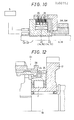
- Figs. 9 and 10 are cross-sectional views of the synchromesh type transmission 6 of the present invention in which the parts identical to those in Fig. 5 are indicated by the same reference numerals and description thereof is omitted.
- a known synchronizing device D1 is mounted on the 1st speed gear train 1M
- the electromagnetic multiple-disk clutch C2 is mounted on the 2nd gear train 2M while the electromagnetic multiple-disk clutch C5 is provided in the 5th gear train 5M.
- the actuator 14 for actuating the electromagnetic multiple-disk clutch C2 and the actuator 15 for actuating the electromagnetic multiple-disk clutch C5 are also provdied. When the electromagnetic multiple-disk clutch C2 is energized, torque is transmitted between the 2nd gear train 2M and the input shaft 8.
- Fig. 10 shows the essential parts of the portion of the transmission on which the electromagnetic multiple-disk clutches C2 and C5 are mounted. These parts have the same structural configuration as those shown in Fig. 6.
- the electromagnetic multiple-disk clutches C2 and C5 are capable of transmitting torque while varying it, as shown in Fig.
- the amount of torque transmitted increases in proportion to current CC or CA supplied to the coil 22. More specifically, the current CC and CA are supplied to the actuators 14 and 15 for the electromagnetic multiple-disk clutches C2 and C5 by the signals CCV and CAV from the processor 34, by which the torque transmitted is increased and decreased and transference of torque is started and broken off.
- the function of the essential parts is the same as that in Fig. 6.
- the automatic change gear control means has the one-way clutch F in the 1st speed gear train 1M which is the lowest speed gear or the 1st speed gear.
- the one-way clutch F is incorporated in the synchronizing device D1 in such a manner as shown in Fig. 12. It idles when the peripheral speed of the output shaft 19 is larger than that of a gear 17 of the 1st gear train 1M which is mounted on the output shaft 19.
- the synchronizing device D1 also includes a blocking ring 24, a synchronizing cone 25, and a sleeve 26. In the above-described arrangement, drive in the 1st speed range, up-shift from the 1st gear to the 2nd gear and down-shift from the 2nd gear to the 1st gear will be performed in the manner described below.
- up-shift from the 1st speed range to the 2nd speed range is achieved by the engagement of the electromagnetic multiple-disk clutch C2 mounted on the 2nd speed gear train 2M. More specifically, as shown in Fig. 13, after the vehicle has started running in the 1st speed range, the engine speed, i.e., the rotational speed N e of the input shaft 8 increases, thereby increasing the rotational speed of the gear 16 of the 1st speed gear train 1M and the N1 of the gear 17. At this time, the electromagnetic multiple-disk clutch C2 mounted on the 2nd gear train 2M is not yet engaged, and a gear 18 of the 2nd speed gear train 2M which is mounted on the output shaft 19 is idling.
- the electromagnetic multiple-disk clutch C2 becomes engaged such that torque is transmitted therethrough when the rotational speed N1 of the gear 17, i.e., the rotational speed N0 of the output shaft 19, exceeds a predetermined value (at a point T2).
- the rotational speed N e of the input shaft 8 i.e., the torque transmitted temporarily reduces, then increases again.
- This increases the rotational speed N0 of the output shaft 19 and the increased rotational speed N0 causes the one-way clutch F to idle, completing gear shift operation from the 1st to 2nd.
- the down-shift from 2nd to 1st is just reverse to that described above, and is achieved only by the disengagement of the electromagnetic multiple-disk clutch C2 mounted on the 2nd gear train 2M. More specifically, when the electromagnetic multiple-disk clutch C2 is disengaged, the opening of a throttle valve becomes large owing the kick-down, increasing the engine speed. This increases the rotational speed N1 of the gear 17 in the 1st gear train 1M which is mounted on the output shaft 19 up to a value which is larger than the rotational speed N0 of the output shaft 19. In consequence, the one-way clutch F is locked, i.e., it is engaged, thereby completing down-shift from 2nd to 1st and enabling torque to be transmitted in the 1st speed range.
- Fig. 14 is a graphic representation of the relationship between rotational speed N e of the input shaft 8 and rotational speed N0 of the output shaft 19 which is obtained when the accelerating pedal is depressed and released while the vehicle is running in the 1st speed range.
- the one-way clutch F idles in hatched portions K of the rotational speed N0 of the output shaft 19 in the graph.
- the output shaft 19 is not driven and the vehicle runs smoothly without generating jolting, as indicated by P in the graph.
- the output shaft is driven by the engine only when the accelerating pedal is depressed, and is not driven and the vehicle runs free while the accelerating pedal is being released, thus allowing jolting of the vehicle caused by the depression and release of the accelerating pedal to be diminished.
- the electromagnetic multiple-disk clutch C2 mounted on the 2nd speed gear train 2M is energized so as to make the 1st gear train 1M idle by means of the one-way clutch F. In consequence, no time lag occurs.
- the vehicle speed i.e., the rotational speed N0 of the output shaft
- gears are shifted from 2nd to 3rd (at a time T3) by actuating the electromagnetic multiple-disk clutch C5 mounted on the 5th speed gear train 5M and causing it to load torque. Therefore, the vehicle speed, i.e., the rotational speed N0 of the output shaft 19, temporarily decreases, and then increases again. In consequence, non-transmission of torque does not occur.
- Up-shift from 3rd to 4th is performed in the same manner as described above. Up-shift from 4th to 5th is achieved only by the engagement of the electromagnetic multiple-disk clutch C5, causing no non-transmission of torque.
- the electromagnetic multiple-disk clutch C2 mounted on the 2nd speed gear train 2M is energized so as to enable torque to be loaded thereto. Therefore, the vehicle speed, i.e., the rotational speed N0 of the output shaft 19, increases, causing no non-transmission of torque.
- Fig. 4 (D) is a flowchart of the gear-shift operations of a known automatic change gear control system which is to be compared with those shown in Fig. 4 (A), 4 (B) or 4 (C).
- the clutch is not limited to a electromagnetic multiple-disk clutch but any transmitting torque varying means which is capable of varying the transmitting torque may be employed together with an actuator for actuating it, such transmitting torque varying means including a friction multiple-disk clutch, a fluid clutch, a fluid multiple-disk clutch.
- transmitting torque varying means including a friction multiple-disk clutch, a fluid clutch, a fluid multiple-disk clutch.
Landscapes
- Engineering & Computer Science (AREA)
- Mechanical Engineering (AREA)
- Chemical & Material Sciences (AREA)
- Combustion & Propulsion (AREA)
- General Engineering & Computer Science (AREA)
- Transportation (AREA)
- Automation & Control Theory (AREA)
- Control Of Transmission Device (AREA)
Applications Claiming Priority (4)
| Application Number | Priority Date | Filing Date | Title |
|---|---|---|---|
| JP181159/87 | 1987-07-22 | ||
| JP62181159A JPS6426056A (en) | 1987-07-22 | 1987-07-22 | Shift controller for automatic transmission |
| JP62181158A JPS6426055A (en) | 1987-07-22 | 1987-07-22 | Shift controller for automatic transmission |
| JP181158/87 | 1987-07-22 |
Publications (3)
| Publication Number | Publication Date |
|---|---|
| EP0300792A2 true EP0300792A2 (de) | 1989-01-25 |
| EP0300792A3 EP0300792A3 (en) | 1990-12-12 |
| EP0300792B1 EP0300792B1 (de) | 1993-10-06 |
Family
ID=26500440
Family Applications (1)
| Application Number | Title | Priority Date | Filing Date |
|---|---|---|---|
| EP88306708A Expired - Lifetime EP0300792B1 (de) | 1987-07-22 | 1988-07-21 | Kontroll-Einrichtungen für automatischen Gangwechsel |
Country Status (3)
| Country | Link |
|---|---|
| US (1) | US4884667A (de) |
| EP (1) | EP0300792B1 (de) |
| DE (2) | DE300792T1 (de) |
Cited By (6)
| Publication number | Priority date | Publication date | Assignee | Title |
|---|---|---|---|---|
| WO1991013271A1 (de) * | 1990-03-01 | 1991-09-05 | Volkswagen Aktiengesellschaft | Verfahren zum schalten eines stufenwechselgetriebes |
| EP0367020B1 (de) * | 1988-10-31 | 1992-12-23 | Volkswagen Aktiengesellschaft | Verfahren zum Schalten eines Stufenwechselgetriebes |
| FR2803355A1 (fr) | 2000-01-04 | 2001-07-06 | Renault | Dispositif de changement de rapports de vitesses notamment pour vehicule automobile, et vehicule automobile equipe d'un tel dispositif |
| EP1251296A2 (de) * | 2001-04-16 | 2002-10-23 | Fuji Jukogyo Kabushiki Kaisha | Automatikgetriebe |
| WO2003037672A1 (en) * | 2001-10-31 | 2003-05-08 | Volvo Lastvagnar Ab | Gear box for motor vehicles |
| FR2851311A1 (fr) * | 2003-02-17 | 2004-08-20 | Jacques Clausin | Dispositif de freinage d'arbre de transmission utilisant un electroaimant et un ou plusieurs capteurs d'angles de rotation destine a la synchronisation des boites de vitesses robotisees |
Families Citing this family (12)
| Publication number | Priority date | Publication date | Assignee | Title |
|---|---|---|---|---|
| US5303794A (en) * | 1991-12-17 | 1994-04-19 | Ford Motor Company | Wheel spin control using electronically controlled clutches and engine controls |
| EP0584457B1 (de) * | 1992-08-26 | 1995-09-06 | Volkswagen Aktiengesellschaft | Verfahren und Vorrichtung zur geregelten Zu- und Abkopplung der Fahrkupplung im Getriebe eines Fahrzeuges |
| JP3528235B2 (ja) * | 1994-05-11 | 2004-05-17 | いすゞ自動車株式会社 | 自動変速装置 |
| GB2297130A (en) * | 1995-01-21 | 1996-07-24 | Ford New Holland Nv | Hydraulic control system regulates pressure supply to sychroniser actuator to increase pressure progressively |
| DE19709417A1 (de) * | 1996-03-14 | 1997-10-30 | Luk Getriebe Systeme Gmbh | Vorrichtung zur Ansteuerung eines Drehmomentübertragungssystems und eines Getriebes, sowie ein Verfahren hierfür |
| US5813940A (en) * | 1996-05-23 | 1998-09-29 | Volkswagen Ag | Transmission clutch control arrangement |
| CN1091416C (zh) * | 1997-01-29 | 2002-09-25 | 倪高松 | 汽车自动变速方法及装置 |
| JP4385651B2 (ja) * | 2003-05-28 | 2009-12-16 | いすゞ自動車株式会社 | 車両のパーキング装置 |
| JP4656206B2 (ja) * | 2008-08-01 | 2011-03-23 | トヨタ自動車株式会社 | 車両用自動変速機の制御装置 |
| JP7135356B2 (ja) * | 2018-03-19 | 2022-09-13 | いすゞ自動車株式会社 | 車両制御装置及び車両制御方法 |
| CN112081914A (zh) * | 2020-09-30 | 2020-12-15 | 坤泰车辆系统(常州)有限公司 | 一种基于电磁助力换挡和同步器结构的电驱系统 |
| CN113669445B (zh) * | 2021-08-24 | 2022-10-28 | 潍柴动力股份有限公司 | 档位切换方法、装置、电子设备、存储介质及程序产品 |
Citations (6)
| Publication number | Priority date | Publication date | Assignee | Title |
|---|---|---|---|---|
| FR2154235A5 (de) * | 1971-09-25 | 1973-05-04 | Fiat Spa | |
| EP0088786A1 (de) * | 1981-09-24 | 1983-09-21 | Western Electric Co | Verfahren und andordnung zum anzeigen der übertragungsweise eines fernmeldesystems. |
| US4463621A (en) * | 1981-12-23 | 1984-08-07 | Ford Motor Company | Multiple countershaft automatic transmission |
| US4497222A (en) * | 1982-01-05 | 1985-02-05 | Mazda Motor Corporation | Clutch control in a multiple clutch type gear transmission for automobile |
| US4658663A (en) * | 1984-03-30 | 1987-04-21 | Nissan Motor Co., Ltd. | Synchromesh transmission suited for use as automotive automatic transmission |
| US4677880A (en) * | 1984-12-28 | 1987-07-07 | Isuzu Motors Limited | Method of controlling automatic transmission in accordance with engine operation |
Family Cites Families (6)
| Publication number | Priority date | Publication date | Assignee | Title |
|---|---|---|---|---|
| US2991661A (en) * | 1958-04-22 | 1961-07-11 | Rambausek Hugo | Multi-speed transmission with only two overrunning clutches, particularly for vehicles |
| DE1530994B2 (de) * | 1967-03-03 | 1974-07-25 | Robert Bosch Gmbh, 7000 Stuttgart | Stirnradschaltgetriebe mit vier Vorwärtsgängen, insbesondere für Kraftfahrzeuge |
| AU537361B2 (en) * | 1981-07-29 | 1984-06-21 | Kubota Ltd. | Transmission with multiple shafts and clutches |
| JPS58146748A (ja) * | 1982-02-22 | 1983-09-01 | Mazda Motor Corp | 複合クラッチ式多段歯車変速機の変速制御方法 |
| JPH0611754A (ja) * | 1992-06-26 | 1994-01-21 | Olympus Optical Co Ltd | カメラの測光システム |
| JPH06326452A (ja) * | 1993-05-14 | 1994-11-25 | Ibiden Co Ltd | プリント配線板への半田供給方法 |
-
1988
- 1988-07-20 US US07/222,535 patent/US4884667A/en not_active Expired - Lifetime
- 1988-07-21 DE DE198888306708T patent/DE300792T1/de active Pending
- 1988-07-21 DE DE88306708T patent/DE3884704T2/de not_active Expired - Fee Related
- 1988-07-21 EP EP88306708A patent/EP0300792B1/de not_active Expired - Lifetime
Patent Citations (6)
| Publication number | Priority date | Publication date | Assignee | Title |
|---|---|---|---|---|
| FR2154235A5 (de) * | 1971-09-25 | 1973-05-04 | Fiat Spa | |
| EP0088786A1 (de) * | 1981-09-24 | 1983-09-21 | Western Electric Co | Verfahren und andordnung zum anzeigen der übertragungsweise eines fernmeldesystems. |
| US4463621A (en) * | 1981-12-23 | 1984-08-07 | Ford Motor Company | Multiple countershaft automatic transmission |
| US4497222A (en) * | 1982-01-05 | 1985-02-05 | Mazda Motor Corporation | Clutch control in a multiple clutch type gear transmission for automobile |
| US4658663A (en) * | 1984-03-30 | 1987-04-21 | Nissan Motor Co., Ltd. | Synchromesh transmission suited for use as automotive automatic transmission |
| US4677880A (en) * | 1984-12-28 | 1987-07-07 | Isuzu Motors Limited | Method of controlling automatic transmission in accordance with engine operation |
Non-Patent Citations (13)
| Title |
|---|
| PATENT ABSTRACTS OF JAPAN, unexamined applications, M section, vol. 12, no. 229, June 29, 1988 THE PATENT OFFICE JAPANESE GOVERNMENT page 103 & JP-A-63 026 452 ( ISUZU ) * |
| PATENT ABSTRACTS OF JAPAN, unexamined applications, M section, vol. 9, no. 128, June 4, 1985 THE PATENT OFFICE JAPANESE GOVERNMENT pages 84-89 & JP-A-60 011 754 ( ISUZU ) * |
| PATENT ABSTRACTS OF JAPAN, unexamined applications, M section, vol. 9, no. 128, June 4, 1985 THE PATENT OFFICE JAPANESE GOVERNMENT pages 84-89 & JP-A-60 011 755 ( ISUZU ) * |
| PATENT ABSTRACTS OF JAPAN, unexamined applications, M section, vol. 9, no. 128, June 4, 1985 THE PATENT OFFICE JAPANESE GOVERNMENT pages 84-89 & JP-A-60 011 757 ( ISUZU ) * |
| PATENT ABSTRACTS OF JAPAN, unexamined applications, M section, vol. 9, no. 128, June 4, 1985 THE PATENT OFFICE JAPANESE GOVERNMENT pages 84-89 & JP-A-60 011 758 ( ISUZU ) * |
| PATENT ABSTRACTS OF JAPAN, unexamined applications, M section, vol. 9, no. 128, June 4, 1985 THE PATENT OFFICE JAPANESE GOVERNMENT pages 84-89 & JP-A-60 011 759 ( ISUZU ) * |
| PATENT ABSTRACTS OF JAPAN, unexamined applications, M section, vol. 9, no. 128, June 4, 1985 THE PATENT OFFICE JAPANESE GOVERNMENT pages 84-89 & JP-A-60 011 760 ( ISUZU ) * |
| PATENT ABSTRACTS OF JAPAN, unexamined applications, M section, vol. 9, no. 128, June 4, 1985 THE PATENT OFFICE JAPANESE GOVERNMENT pages 84-89 & JP-A-60 011 761 ( ISUZU ) * |
| PATENT ABSTRACTS OF JAPAN, unexamined applications, M section, vol. 9, no. 128, June 4, 1985 THE PATENT OFFICE JAPANESE GOVERNMENT pages 84-89 & JP-A-60 011 762 ( ISUZU ) * |
| PATENT ABSTRACTS OF JAPAN, unexamined applications, M section, vol. 9, no. 128, June 4, 1985 THE PATENT OFFICE JAPANESE GOVERNMENT pages 84-89 & JP-A-60 011 763 ( ISUZU ) * |
| PATENT ABSTRACTS OF JAPAN, unexamined applications, M section, vol. 9, no. 128, June 4, 1985 THE PATENT OFFICE JAPANESE GOVERNMENT pages 84-89 & JP-A-60 011 764 ( ISUZU ) * |
| PATENT ABSTRACTS OF JAPAN, unexamined applications, M section, vol. 9, no. 128, June 4, 1985 THE PATENT OFFICE JAPANESE GOVERNMENT pages 84-89 & JP-A-60 011 768 ( ISUZU ) * |
| PATENT ABSTRACTS OF JAPAN, unexamined applications, M section, vol. 9, no. 128, June 4, 1985 THE PATENT OFFICE JAPANESE GOVERNMENT pages 84-89 & JP-A-60 011 770 ( ISUZU ) * |
Cited By (9)
| Publication number | Priority date | Publication date | Assignee | Title |
|---|---|---|---|---|
| EP0367020B1 (de) * | 1988-10-31 | 1992-12-23 | Volkswagen Aktiengesellschaft | Verfahren zum Schalten eines Stufenwechselgetriebes |
| WO1991013271A1 (de) * | 1990-03-01 | 1991-09-05 | Volkswagen Aktiengesellschaft | Verfahren zum schalten eines stufenwechselgetriebes |
| FR2803355A1 (fr) | 2000-01-04 | 2001-07-06 | Renault | Dispositif de changement de rapports de vitesses notamment pour vehicule automobile, et vehicule automobile equipe d'un tel dispositif |
| EP1251296A2 (de) * | 2001-04-16 | 2002-10-23 | Fuji Jukogyo Kabushiki Kaisha | Automatikgetriebe |
| EP1251296A3 (de) * | 2001-04-16 | 2004-01-21 | Fuji Jukogyo Kabushiki Kaisha | Automatikgetriebe |
| US6826974B2 (en) | 2001-04-16 | 2004-12-07 | Fuji Jukogyo Kabushiki Kaisha | Automatic transmission |
| WO2003037672A1 (en) * | 2001-10-31 | 2003-05-08 | Volvo Lastvagnar Ab | Gear box for motor vehicles |
| US7134355B2 (en) | 2001-10-31 | 2006-11-14 | Volvo Lastvagnar Ab | Gear box for motor vehicles |
| FR2851311A1 (fr) * | 2003-02-17 | 2004-08-20 | Jacques Clausin | Dispositif de freinage d'arbre de transmission utilisant un electroaimant et un ou plusieurs capteurs d'angles de rotation destine a la synchronisation des boites de vitesses robotisees |
Also Published As
| Publication number | Publication date |
|---|---|
| DE300792T1 (de) | 1989-10-05 |
| EP0300792B1 (de) | 1993-10-06 |
| DE3884704D1 (de) | 1993-11-11 |
| US4884667A (en) | 1989-12-05 |
| EP0300792A3 (en) | 1990-12-12 |
| DE3884704T2 (de) | 1994-03-10 |
Similar Documents
| Publication | Publication Date | Title |
|---|---|---|
| EP0300792B1 (de) | Kontroll-Einrichtungen für automatischen Gangwechsel | |
| EP1347195B1 (de) | Doppelkupplungsgetriebe | |
| EP0173117B1 (de) | Automatisches Getriebe und Verfahren zu seiner Steuerung | |
| JP3581991B2 (ja) | 機械式自動変速機の制御装置及び方法 | |
| EP0628443B1 (de) | Verfahren für eine Auskuppel-Steuerung | |
| US7344474B2 (en) | Control for selecting automated transmission system shift strategy | |
| EP0562803B1 (de) | Verfahren und Vorrichtung zur Gangschaltsteuerung eines Fahrzeug-Automatikgetriebes | |
| EP0273735B1 (de) | Elektronische Steuervorrichtung für ein automatisches Getriebe | |
| US5517411A (en) | Neutral attainment control system/method for controlling shifting in vehicular automated mechanical transmission systems | |
| JPH0648025B2 (ja) | 複クラッチを備えた車両用同期噛合式自動変速装置 | |
| WO2005075239A1 (ja) | 車両用動力伝達装置のエンジン制御装置 | |
| JPH0470509B2 (de) | ||
| JPH102408A (ja) | 3→1速スキップ変速時の変速感制御装置 | |
| JP2001050379A (ja) | 自動車の制御装置 | |
| EP1508468B1 (de) | Steuerungsvorrichtung und -verfahren eines Schaltgetriebes | |
| EP1310696A1 (de) | Steuereinrichtung einer automatischen Kupplung | |
| JP4007321B2 (ja) | 自動車の制御装置 | |
| US7252622B2 (en) | Transmission, and control system and control method for the transmission | |
| JP2002257225A (ja) | 自動変速機の制御装置 | |
| JPS621142B2 (de) | ||
| JP3011567B2 (ja) | 変速装置の変速制御方法及び装置 | |
| JP2001271921A (ja) | 変速機とその自動変速制御方法 | |
| JPS6326452A (ja) | 自動変速機の変速制御装置 | |
| JPH0585773B2 (de) | ||
| Dunkley et al. | Easy Shifting Beyond Synchromesh Technology |
Legal Events
| Date | Code | Title | Description |
|---|---|---|---|
| PUAI | Public reference made under article 153(3) epc to a published international application that has entered the european phase |
Free format text: ORIGINAL CODE: 0009012 |
|
| AK | Designated contracting states |
Kind code of ref document: A2 Designated state(s): DE GB |
|
| DET | De: translation of patent claims | ||
| PUAL | Search report despatched |
Free format text: ORIGINAL CODE: 0009013 |
|
| AK | Designated contracting states |
Kind code of ref document: A3 Designated state(s): DE GB |
|
| RHK1 | Main classification (correction) |
Ipc: F16H 5/66 |
|
| 17P | Request for examination filed |
Effective date: 19901127 |
|
| 17Q | First examination report despatched |
Effective date: 19920512 |
|
| GRAA | (expected) grant |
Free format text: ORIGINAL CODE: 0009210 |
|
| AK | Designated contracting states |
Kind code of ref document: B1 Designated state(s): DE GB |
|
| REF | Corresponds to: |
Ref document number: 3884704 Country of ref document: DE Date of ref document: 19931111 |
|
| PLBE | No opposition filed within time limit |
Free format text: ORIGINAL CODE: 0009261 |
|
| STAA | Information on the status of an ep patent application or granted ep patent |
Free format text: STATUS: NO OPPOSITION FILED WITHIN TIME LIMIT |
|
| 26N | No opposition filed | ||
| PGFP | Annual fee paid to national office [announced via postgrant information from national office to epo] |
Ref country code: GB Payment date: 20010615 Year of fee payment: 14 |
|
| PGFP | Annual fee paid to national office [announced via postgrant information from national office to epo] |
Ref country code: DE Payment date: 20010625 Year of fee payment: 14 |
|
| REG | Reference to a national code |
Ref country code: GB Ref legal event code: IF02 |
|
| PG25 | Lapsed in a contracting state [announced via postgrant information from national office to epo] |
Ref country code: GB Free format text: LAPSE BECAUSE OF NON-PAYMENT OF DUE FEES Effective date: 20020721 |
|
| PG25 | Lapsed in a contracting state [announced via postgrant information from national office to epo] |
Ref country code: DE Free format text: LAPSE BECAUSE OF NON-PAYMENT OF DUE FEES Effective date: 20030201 |
|
| GBPC | Gb: european patent ceased through non-payment of renewal fee |
Effective date: 20020721 |