EP0300360B1 - Anschlussvorrichtung für Mischarmaturen und Verfahren zum Anschluss der Armatur - Google Patents
Anschlussvorrichtung für Mischarmaturen und Verfahren zum Anschluss der Armatur Download PDFInfo
- Publication number
- EP0300360B1 EP0300360B1 EP88111286A EP88111286A EP0300360B1 EP 0300360 B1 EP0300360 B1 EP 0300360B1 EP 88111286 A EP88111286 A EP 88111286A EP 88111286 A EP88111286 A EP 88111286A EP 0300360 B1 EP0300360 B1 EP 0300360B1
- Authority
- EP
- European Patent Office
- Prior art keywords
- connecting piece
- connecting device
- housing
- channel
- respect
- Prior art date
- Legal status (The legal status is an assumption and is not a legal conclusion. Google has not performed a legal analysis and makes no representation as to the accuracy of the status listed.)
- Expired - Lifetime
Links
- 238000000034 method Methods 0.000 title claims description 5
- XLYOFNOQVPJJNP-UHFFFAOYSA-N water Substances O XLYOFNOQVPJJNP-UHFFFAOYSA-N 0.000 claims abstract description 27
- 238000011010 flushing procedure Methods 0.000 claims description 13
- 238000011144 upstream manufacturing Methods 0.000 claims description 6
- 230000001681 protective effect Effects 0.000 claims description 3
- 239000000463 material Substances 0.000 claims 1
- 239000006260 foam Substances 0.000 description 6
- 238000009434 installation Methods 0.000 description 4
- 238000007789 sealing Methods 0.000 description 3
- 238000010276 construction Methods 0.000 description 2
- 230000002028 premature Effects 0.000 description 2
- 238000004026 adhesive bonding Methods 0.000 description 1
- 239000002131 composite material Substances 0.000 description 1
- 238000009413 insulation Methods 0.000 description 1
- 238000004519 manufacturing process Methods 0.000 description 1
- 238000003825 pressing Methods 0.000 description 1
- 230000001105 regulatory effect Effects 0.000 description 1
- 239000008237 rinsing water Substances 0.000 description 1
- 230000003584 silencer Effects 0.000 description 1
- 230000001360 synchronised effect Effects 0.000 description 1
Images



Classifications
-
- E—FIXED CONSTRUCTIONS
- E03—WATER SUPPLY; SEWERAGE
- E03C—DOMESTIC PLUMBING INSTALLATIONS FOR FRESH WATER OR WASTE WATER; SINKS
- E03C1/00—Domestic plumbing installations for fresh water or waste water; Sinks
- E03C1/02—Plumbing installations for fresh water
- E03C1/04—Water-basin installations specially adapted to wash-basins or baths
- E03C1/042—Arrangements on taps for wash-basins or baths for connecting to the wall
-
- Y—GENERAL TAGGING OF NEW TECHNOLOGICAL DEVELOPMENTS; GENERAL TAGGING OF CROSS-SECTIONAL TECHNOLOGIES SPANNING OVER SEVERAL SECTIONS OF THE IPC; TECHNICAL SUBJECTS COVERED BY FORMER USPC CROSS-REFERENCE ART COLLECTIONS [XRACs] AND DIGESTS
- Y10—TECHNICAL SUBJECTS COVERED BY FORMER USPC
- Y10T—TECHNICAL SUBJECTS COVERED BY FORMER US CLASSIFICATION
- Y10T137/00—Fluid handling
- Y10T137/0318—Processes
- Y10T137/0402—Cleaning, repairing, or assembling
- Y10T137/0491—Valve or valve element assembling, disassembling, or replacing
-
- Y—GENERAL TAGGING OF NEW TECHNOLOGICAL DEVELOPMENTS; GENERAL TAGGING OF CROSS-SECTIONAL TECHNOLOGIES SPANNING OVER SEVERAL SECTIONS OF THE IPC; TECHNICAL SUBJECTS COVERED BY FORMER USPC CROSS-REFERENCE ART COLLECTIONS [XRACs] AND DIGESTS
- Y10—TECHNICAL SUBJECTS COVERED BY FORMER USPC
- Y10T—TECHNICAL SUBJECTS COVERED BY FORMER US CLASSIFICATION
- Y10T137/00—Fluid handling
- Y10T137/5109—Convertible
- Y10T137/5196—Unit orientable in a single location between plural positions
-
- Y—GENERAL TAGGING OF NEW TECHNOLOGICAL DEVELOPMENTS; GENERAL TAGGING OF CROSS-SECTIONAL TECHNOLOGIES SPANNING OVER SEVERAL SECTIONS OF THE IPC; TECHNICAL SUBJECTS COVERED BY FORMER USPC CROSS-REFERENCE ART COLLECTIONS [XRACs] AND DIGESTS
- Y10—TECHNICAL SUBJECTS COVERED BY FORMER USPC
- Y10T—TECHNICAL SUBJECTS COVERED BY FORMER US CLASSIFICATION
- Y10T137/00—Fluid handling
- Y10T137/598—With repair, tapping, assembly, or disassembly means
- Y10T137/6011—Assembling, disassembling, or removing cartridge type valve [e.g., insertable and removable as a unit, etc.]
- Y10T137/6014—Faucet type [e.g., domestic water use, etc.]
-
- Y—GENERAL TAGGING OF NEW TECHNOLOGICAL DEVELOPMENTS; GENERAL TAGGING OF CROSS-SECTIONAL TECHNOLOGIES SPANNING OVER SEVERAL SECTIONS OF THE IPC; TECHNICAL SUBJECTS COVERED BY FORMER USPC CROSS-REFERENCE ART COLLECTIONS [XRACs] AND DIGESTS
- Y10—TECHNICAL SUBJECTS COVERED BY FORMER USPC
- Y10T—TECHNICAL SUBJECTS COVERED BY FORMER US CLASSIFICATION
- Y10T137/00—Fluid handling
- Y10T137/6851—With casing, support, protector or static constructional installations
- Y10T137/6966—Static constructional installations
- Y10T137/6969—Buildings
- Y10T137/698—Wall
-
- Y—GENERAL TAGGING OF NEW TECHNOLOGICAL DEVELOPMENTS; GENERAL TAGGING OF CROSS-SECTIONAL TECHNOLOGIES SPANNING OVER SEVERAL SECTIONS OF THE IPC; TECHNICAL SUBJECTS COVERED BY FORMER USPC CROSS-REFERENCE ART COLLECTIONS [XRACs] AND DIGESTS
- Y10—TECHNICAL SUBJECTS COVERED BY FORMER USPC
- Y10T—TECHNICAL SUBJECTS COVERED BY FORMER US CLASSIFICATION
- Y10T137/00—Fluid handling
- Y10T137/8593—Systems
- Y10T137/86493—Multi-way valve unit
- Y10T137/86815—Multiple inlet with single outlet
Definitions
- the invention relates to a device with the features specified in the preamble of claim 1 and to a method for connecting hot and cold water mixers.
- a connection device for mixer taps is previously known from AT-PS 177 382.
- a relatively simple and flat connector is provided, to which the mixer fitting can be attached with a flange connection.
- this device it is necessary that the connecting piece is arranged precisely in the building wall, since subsequent adjustment is not provided when the mixer tap is being installed.
- connections for cold and hot water are exchanged in the flush-mounted connector when installing the pipeline network. This is usually only determined when the mixer tap is to be connected. In order to correct the connections, it is then necessary to relocate the pipelines, which is extremely time-consuming, particularly when the pipelines are flush-mounted.
- a sanitary fitting connection element is known from EP-PS 0 119 960, in which a mixer fitting with a plug part can be inserted into a bore in a connecting piece.
- the connector should consist of a housing in which a battery piece is arranged, which carries the receiving bore for the plug part.
- the invention has for its object to improve the connecting device specified in the preamble of claim 1, in particular to create easy adaptability to different installation situations with simple means, and to propose an installation method.
- This object is achieved by the features specified in the characterizing part of claim 1 and claim 10. Further refinements of the invention are specified in claims 2 to 9.
- DE-OS 32 39 924 it was known from DE-OS 32 39 924 to provide a front part in a synchronous shut-off and regulating valve for adapting the water flow during assembly.
- connection device shown in Figure 1 is arranged in a building wall 7 and is formed by a connection piece 1, a mixer fitting 2, a fitting piece 3 and a foam part 5.
- the foam part 5 takes up the connector 1 in its pot-like cavity and is used for sound insulation from the building wall.
- the foam can, for example, be applied directly to the rear of the connector 1, so that a composite body is formed.
- the foam part 5 can also be connected to the connector 1, for example by gluing or in another suitable manner.
- the wall of the foam part protruding from the building wall can be cut to length depending on the individual installation depth at the construction site.
- the connector 1 is, as can be seen in particular from Figure 2, with pipes 10 for cold and hot water sealed to the holes 11 and fixed with the help of noise-isolating screws 13 before bricking in on the building wall 7.
- the holes 11 for cold and hot water are passed through the connector 1 and are each connected to a transversely arranged bore 12.
- the mixing valve 2 is connected to its housing 20 on the projecting end face.
- the housing 20 is approximately cylindrical and has an annular flange 27 on the upstream end face, with which the connection to the connection piece 1 can be established with the aid of four symmetrically arranged fastening screws 28.
- a cylindrical adapter 3 is rotatably arranged concentrically in the upstream end face of the housing 20. The upstream end face of the adapter 3, as shown in particular in FIG.
- inlet channel 31a has two separate inlet channels 31a and 31, which are approximately aligned with the bores 12 in the connector 1 and are arranged symmetrically to the central axis 21.
- One inlet channel 31 a is guided essentially coaxially through the adapter 3 and opens into a chamber 23 which is formed concentrically to the central axis and which is connected to a supply channel 22 a in the housing 20.
- the inlet channel 31b is led radially out of the adapter 3 and opens into an annular channel 24 which is open in the housing 20 for the adapter 3 and which is connected to a side channel 25 in the housing 20 with a supply channel 22b.
- the feed channels 22a, 22b are connected to a mixing valve 8 arranged in the housing 20, the mixing valve 8 having an adjusting handle 81 which can be moved in two degrees of freedom, so that on the one hand the mixing ratio of hot and cold water and on the other hand the total outflow quantity of the mixed water can be determined.
- the fitting 3 is provided on its end face with sealing rings for the connector 1 and on its outer surface with sealing rings for the housing 20, so that premature escape of cold or hot water or premature mixing of cold and hot water is excluded.
- depressions 30 are provided on the upstream end face of the adapter 3 coaxially to the inlet channels 31 a and 31 b, in each of which an annular body 32 is arranged.
- depressions 30 are also provided in the connecting piece 1, as can be seen in particular from FIG.
- a protective screen 32 is fastened to the ring body 32 in the inner region, while sealing rings are assigned to each of the end faces.
- a check valve can also be expediently provided in the area of the ring body 32.
- a silencer 4 is arranged in an enlarged bore in the feed channels 22a and 22b. The enlarged bore of the feed channel 22b is closed on the upstream end side with a plug 26, so that safe, separate guidance of cold and hot water is ensured
Landscapes
- Life Sciences & Earth Sciences (AREA)
- Engineering & Computer Science (AREA)
- Hydrology & Water Resources (AREA)
- Public Health (AREA)
- Water Supply & Treatment (AREA)
- Health & Medical Sciences (AREA)
- Domestic Plumbing Installations (AREA)
- Multiple-Way Valves (AREA)
- Valve Housings (AREA)
- Processing Of Terminals (AREA)
- Underground Or Underwater Handling Of Building Materials (AREA)
- Preparation Of Clay, And Manufacture Of Mixtures Containing Clay Or Cement (AREA)
- Lining Or Joining Of Plastics Or The Like (AREA)
Description
- Die Erfindung bezieht sich auf eine Vorrichtung mit den im Oberbegriff des Anspruchs 1 angegebenen Merkmalen und auf ein Verfahren zum Anschluß von Warm- und Kaltwassermischarmaturen. Eine derartige Anschlußvorrichtung für Mischarmaturen ist aus der AT-PS 177 382 vorbekannt. Hierbei ist ein relativ einfaches und flachbauendes Anschlußstück vorgesehen, an dem mit einer Flanschverbindung die Mischarmatur befestigbar ist. Bei dieser Einrichtung ist es jedoch erforderlich, daß das Anschlußstück entsprechend genau in der Gebäudewand angeordnet wird, da ein nachträgliches Justieren bei der Anmontage der Mischbatterie nicht vorgesehen ist. Darüber hinaus kann es durchaus vorkommen, daß bei der Installation des Rohrleitungsnetzes Anschlüsse für Kalt- und Warmwasser in dem Unterputz-Anschlußstück vertauscht werden. Dieses wird meist erst festgestellt, wenn die Mischarmatur angeschlossen werden soll. Zur Richtigstellung der Anschlüsse ist dann ein Neuverlegen der Rohrleitungen erforderlich, was insbesondere bei Unterputz verlegten Rohrleitungen äußerst aufwendig ist.
- Ferner ist aus der EP-PS 0 119 960 ein Sanitär-Armaturanschlußorgan bekannt, bei dem eine Mischarmatur mit einem Steckerteil in eine Bohrung eines Anschlußstücks einführbar ist. Das Anschlußstück soll dabei aus einem Gehäuse bestehen, in dem ein Batteriestück angeordnet ist, welches die Aufnahmebohrung für das Steckerteil trägt. Bei dieser Einrichtung ist zwar eine nachträgliche Korrektur bei vertauschten Anschlüssen sowie eine Justierung der Mischbatterie möglich, sie ist aber relativ kompliziert und somit aufwendig in der Herstellung. Außerdem wird durch die erforderliche Aufnahmebohrung für das Steckerteil ein verhältnismäßig tief ausgebildetes Anschlußstück benötigt.
- Der Erfindung liegt die Aufgabe zugrunde, die im Oberbegriff des Anspruchs 1 angegebene Anschlußvorrichtung zu verbessern, insbesondere mit einfachen Mitteln eine leichte Anpaßbarkeit an verschiedene Installationssituationen zu schaffen, und ein Installationsverfahren vorzuschlagen. Diese Aufgabe wird erfindungsgemäß durch die im kennzeichnenden Teil des Anspruchs 1 bzw. des Anspruchs 10 angegebenen Merkmale gelöst. Weitere Ausgestaltungen der Erfindung sind in den Ansprüchen 2 bis 9 angegeben. Schließlich sei angemerkt, daß es aus der DE-OS 32 39 924 bekannt war, bei einem Synchronabsperr-und Regulierventil ein Vorsatzteil zur Anpassung der Wasserführung bei der Montage vorzusehen.
- Die mit der Erfindung erzielbaren Vorteile bestehen insbesondere darin,
- a) daß zwischen der Mischarmatur und dem Anschlußstück ein Paßstück angeordnet ist, das durch Verdrehen um 180° die gewünschte Zuflußrichtung von Warm- und Kaltwasser zur jeweils nachgeschalteten Mischarma tur, entsprechend den funktionellen Forderungen, eingestellt werden kann und außerdem das Gehäuse der Mischbatterie auf dem Paßstück beliebig verdrehbar ist, wodurch eine Schräglage der Wassersteckdose bzw. des Anschlußstücks ausgleichbar ist;
- b) daß sämtliche, die Funktion beeinflussenden Teile sich im Gehäuse der Mischarmatur befinden, wobei lediglich die Mindestfunktion der einfachen Wasserzuführung der Wassersteckdose bzw. dem Anschlußstück zugeordnet ist;
- c) daß im Rohbauzustand sämtliche Funktionsteile der Mischarmatur zugeordnet bleiben und nicht mit der Wassersteckdose verbunden sind;
- d) daß mittels kombiniertem Abdrück- und Spüldeckel ein für die Funktionsteile gefahrloses Spülen und Abdrücken jederzeit möglich ist;
- e) daß aufgrund der Anordnung der Funktionsteile im Gehäuse der Mischarmatur eine äußerst geringe Bautiefe der Wassersteckdose bzw. des Anschlußstücks ermöglicht ist;
- f) daß mit den vorgegebenen Wasserführungen eine hohe Universalität und kostengünstige Gestaltung gewährleistet ist, da Rückflußverhinderer, Schmutzfang siebe, Schalldämpfer etc. ausschließlich dem Gehäuse der Mischarmatur je nach Bedarf zugeordnet werden können.
- Ein Ausführungsbeispiel der Erfindung ist in der Zeichnung dargestellt und wird im folgenden näher beschrie ben. Es zeigt
- Figur 1 eine an einer Gebäudewand angeordneten Anschlußvorrichtung mit verbundener Mischarmatur im Schnitt;
- Figur 2 ein Anschlußstück gemäß Figur 1 in Draufsicht;
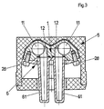
- Figur 3 ein fabrikmäßig ausgeliefertes Anschlußstück mit Abdrück- und Spüldeckel im Schnitt;
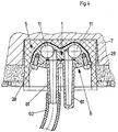
- Figur 4 das Anschlußstück gemäß Figur 3 in einer Gebäudewand installiert, wobei eine Rohrleitung sich in Spülposition befindet;
- Figur 5 das Paßstück gemäß Figur 1 im Längsschnitt;
- Figur 6 das Paßstück gemäß Figur 5 in Druntersicht;
- Figur 7 das Paßstück gemäß Figur 5 in Draufsicht.
- Die in Figur 1 dargestellte Anschlußvorrichtung ist in einer Gebäudewand 7 angeordnet und wird von einem Anschlußstück 1, einer Mischarmatur 2, einem Paßstück 3 sowie einem Schaumstoffteil 5 gebildet. Das Schaumstoffteil 5 nimmt in seinem topfartigen Hohlraum das Anschlußstück 1 auf und dient zur Schallisolierung gegenüber der Gebäudewand. Der Schaumstoff kann z.B. unmittelbar an der Rückseite des Anschlußstücks 1 aufgebracht sein, so daß ein Verbundkörper entsteht. Das Schaumstoffteil 5 kann aber auch z.B. durch Klebung oder in anderer geeigneter Weise mit dem Anschlußstück 1 verbunden sein. Die aus der Gebäudewand vorkragende Wandung des Schaumstoffteils kann in Abhängigkeit von der individuellen Einbautiefe an der Baustelle entsprechend abgelängt werden. Das Anschlußstück 1 ist, wie es insbesondere aus Figur 2 ersichtlich ist, mit Rohrleitungen 10 für Kalt-und Warmwasser mit den Bohrungen 11 gedichtet verbunden und mit Hilfe von geräuschisolierend ausgebildeten Schrauben 13 vor dem Einmauern an der Gebäudewand 7 fixiert. Die Bohrungen 11 für Kalt- und Warmwasser sind durch das Anschlußstück 1 hindurchgeführt und stehen jeweils mit einer quer angeordneten Bohrung 12 in Verbindung. An der vorstehenden Stirnseite ist die Mischarmatur 2 mit ihrem Gehäuse 20 angeschlossen. Das Gehäuse 20 ist etwa zylindrisch ausgebildet und trägt an der stromaufwärts gelegenen Stirnseite einen Ringflansch 27, mit dem mit Hilfe von vier symmetrisch angeordneten Befestigungsschrauben 28 die Verbindung zum Anschlußstück 1 herstellbar ist. Konzentrisch in der stromaufwärts gelegenen Stimfläche des Gehäuses 20 ist ein zylindrisches Paßstück 3 drehbar angeordnet. Die stromaufwärts gelegene Stirnseite des Paßstücks 3, wie es insbesondere auch in Figur 6 dargestellt ist, weist zwei getrennte Einlaßkanäle 31a und 31 auf, die mit den Bohrungen 12 im Anschlußstück 1 etwa fluchten und symmetrisch zur Mittelachse 21 angeordnet sind. Der eine Einlaßkanal 31 a wird dabei im wesentlichen koaxial durch das Paßstück 3 hindurchgeführt und mündet in eine konzentrisch zur Mittelachse ausgebildete Kammer 23, die mit einem Zuführungskanal 22a im Gehäuse 20 verbunden ist. Der Einlaßkanal 31b ist aus dem Paßstück 3 radial herausgeführt und mündet in einem zum Paßstück 3 offen in dem Gehäuse 20 ausgebildeten Ringkanal 24, welcher mit einem Seitenkanal 25 in dem Gehäuse 20 mit einem Zuführungskanal 22b verbunden ist. Die Zuführungskanäle 22a, 22b sind mit einem in dem Gehäuse 20 angeordneten Mischventil 8 verbunden, wobei das Mischventil 8 einen in zwei Freiheitsgraden bewegbaren Stellgriff 81 aufweist, so daß einerseits das Mischungsverhältnis von Warm- und Kaltwasser und andererseits die Gesamtausflußmenge des Mischwassers bestimmt werden kann. Das Paßstück 3 ist an seiner Stimfläche mit Dichtringen zum Anschlußstück 1 und an seiner Mantelfläche mit Dichtringen zum Gehäuse 20 versehen, so daß ein vorzeitiger Austritt von Kalt-oder Warmwasser oder ein vorzeitiges Vermischen von Kalt- und Warmwasser ausgeschlossen ist. Außerdem sind an der stromaufwärts gelegenen Stirnseite des Paßstücks 3 koaxial zu den Einlaßkanälen 31 a und 31 b Einsenkungen 30 vorgesehen, in denen jeweils ein Ringkörper 32 angeordnet ist. Entsprechend konzentrisch zu den Bohrungen 12 sind in dem Anschlußstück 1 ebenfalls Einsenkungen 30 vorgesehen, wie insbesondere aus Figur 2 zu entnehmen ist, so daß in der angeschlossenen Stellung das Paßstück 3 drehfest mit dem Anschlußstück 1 verbunden ist. An dem Ringkörper 32 ist im inneren Bereich ein Schutzsieb 32 befestigt, während an den Stirnseiten jeweils Dichtringe zugeordnet sind. Neben dem Schutzsieb 33 kann im Bereich der Ringkörper 32 zweckmäßig jeweils noch ein Rückschlagventil vorgesehen sein. In Strömungsrichtung, hinter dem Paßstück 3, sind in den Zuführungskanälen 22a und 22b jeweils ein Schalldämpfer 4 in einer erweiterten Bohrung angeordnet. Die erweiterte Bohrung des Zuführungskanals 22b ist an der stromaufwärts gelegenen Stimseite mit einem Stopfen 26 verschlossen, so daß eine sichere, getrennte Führung von Kalt- und Warmwasser gewährleistet ist
- Der Anschluß der Mischarmatur kann in folgen-
- der Weise vorgenommen werden: Das Anschlußstück 1 wird fabrikmäßig mit einem Schaumstoffteil 5 und einem Abdrück- und Spüldeckel 6 versehen, wie es in Figur 3 dargestellt ist. Dieses fabrikmäßige Anschlußstück 1 wird auf der Baustelle mit den Rohrleitungen 10, wie in Figur 2 dargestellt, verbunden und an der Gebäudewand befestigt. Sobald die Rohrleitung fertig installiert ist, kann mit Hilfe einer Druckprobe die Dichtheit des Leitungssystems festgestellt werden, da ja die Bohrungen 11 im Anschlußstück 1 von dem Abdrück-und Spüldeckel 6 sicher abgedichtet sind. Sobald die Rohbaumaßnahmen abgeschlossen sind oder die Mischarmatur 2 mit dem Anschlußstück 1 verbunden werden soll, können die vorkragenden, geschlossenen Enden der Rohrstutzen 61 abgetrennt werden, so daß nun die Kalt- und Warmwasserleitung separat spülbar ist. Zum besseren Auffangen des austretenden Spülwassers können zweckmäßig Schläuche 62 über die offenen Rohrstutzen 61 gestreift werden, wie es insbesondere in Figur 4 dargestellt ist.
- Nach dem Abschließen des Spülvorgangs werden die Befestigungsschrauben 28 gelöst und der Abdrück- und Spüldeckel 6 entfernt. Nunmehr kann die Mischarmatur 2 mit ihrem Gehäuse 20, mit dem Paßstück 3 und den zugehörigen Dichtungen auf das Anschlußstück 1 aufgesetzt und mit den Befestigungsschrauben 28 in der Stecklage gesichert werden.
- Wird hiemach z.B. festgestellt, daß die Anschlüsse von Kalt- und Warmwasser seitenverkehrt vorgenommen worden sind, so kann durch erneutes Lösen der Befestigungsschrauben das Paßstück 3 mit einer um 180° zum Anschluß stück 1 gedrehten Stellung angeschlossen werden, wonach dann eine korrekte Kalt- und Warmwasserzuführung gegeben ist Der Mischwasserauslauf der Mischarmatur 2 befindet sich unterhalb des Mischventils 8 und ist in der Zeichnung, insbesondere Figur 1, nicht sichtbar. Durch die zylindrische Ausbildung des Paßstücks 3 kann das Gehäuse 20 und mit ihm der Mischwasserauslauf in einer beliebigen, vorzugsweise senkrechten Drehstellung unabhängig zur Drehstellung des Anschlußstücks 1 fixiert werden.
Claims (10)
Priority Applications (1)
| Application Number | Priority Date | Filing Date | Title |
|---|---|---|---|
| AT88111286T ATE52821T1 (de) | 1987-07-18 | 1988-07-14 | Anschlussvorrichtung fuer mischarmaturen und verfahren zum anschluss der armatur. |
Applications Claiming Priority (2)
| Application Number | Priority Date | Filing Date | Title |
|---|---|---|---|
| DE3723828 | 1987-07-18 | ||
| DE19873723828 DE3723828A1 (de) | 1987-07-18 | 1987-07-18 | Anschlussvorrichtung fuer mischarmaturen und verfahren zum anschluss der armatur |
Publications (2)
| Publication Number | Publication Date |
|---|---|
| EP0300360A1 EP0300360A1 (de) | 1989-01-25 |
| EP0300360B1 true EP0300360B1 (de) | 1990-05-16 |
Family
ID=6331873
Family Applications (1)
| Application Number | Title | Priority Date | Filing Date |
|---|---|---|---|
| EP88111286A Expired - Lifetime EP0300360B1 (de) | 1987-07-18 | 1988-07-14 | Anschlussvorrichtung für Mischarmaturen und Verfahren zum Anschluss der Armatur |
Country Status (5)
| Country | Link |
|---|---|
| US (1) | US4846207A (de) |
| EP (1) | EP0300360B1 (de) |
| AT (1) | ATE52821T1 (de) |
| DE (2) | DE3723828A1 (de) |
| ES (1) | ES2015979B3 (de) |
Families Citing this family (18)
| Publication number | Priority date | Publication date | Assignee | Title |
|---|---|---|---|---|
| DE3907585A1 (de) * | 1989-03-09 | 1990-09-13 | Grohe Armaturen Friedrich | Anschlussvorrichtung fuer mischarmaturen |
| DE3907587A1 (de) * | 1989-03-09 | 1990-09-13 | Grohe Armaturen Friedrich | Anschlussvorrichtung fuer wasserarmaturen |
| DE3907586A1 (de) * | 1989-03-09 | 1990-09-13 | Grohe Armaturen Friedrich | Abschlussvorrichtung fuer mischarmaturen |
| US5029606A (en) * | 1989-12-05 | 1991-07-09 | Kuhlthau Jr Paul W | Wall-mounted hook-up assemblies for washing machine and lavatory |
| CH685205A5 (de) * | 1992-05-18 | 1995-04-28 | Fides Treuhand Gmbh | Anschlussvorrichtung für eine sanitäre Mischarmatur. |
| US5518027A (en) * | 1992-09-30 | 1996-05-21 | Ntn Corporation | Valve assembly |
| DE59502305D1 (de) * | 1994-04-18 | 1998-07-02 | Wallisellen Ag Armaturen | Einpunktarmatur |
| DE4421387B4 (de) * | 1994-06-18 | 2005-04-07 | Grohe Water Technology Ag & Co. Kg | Einlochmischbatterie |
| DE19605328A1 (de) * | 1996-02-14 | 1997-08-21 | Grohe Kg Hans | Sanitärarmatur |
| DE19710782C2 (de) * | 1997-03-17 | 2002-08-01 | Ideal Standard | Sanitärarmatur |
| DE10109383C2 (de) * | 2001-02-27 | 2003-04-10 | Viessmann Gmbh & Co | Justierelementensatz für Gashähne |
| DE102004034150B4 (de) * | 2004-07-15 | 2008-10-09 | Hansa Metallwerke Ag | Sanitäre Unterputzarmatur |
| US20060231140A1 (en) * | 2005-04-15 | 2006-10-19 | Mcnerney Gerald J | Plaster guard for a wall mounted faucet valve assembly |
| ATE411430T1 (de) * | 2005-12-15 | 2008-10-15 | Arwa Ag | Anschlussvorrichtung für eine wandmontierte unterputzarmatur |
| DE102011076828A1 (de) | 2011-05-31 | 2012-12-06 | Hansgrohe Se | Ventileinsatz für eine Sanitärarmatur |
| CN202531902U (zh) * | 2012-03-30 | 2012-11-14 | 浙江嘉德利卫浴有限公司 | 一种入墙式水龙头预埋集成模块 |
| DE102014100801B4 (de) | 2014-01-24 | 2022-05-19 | Kludi Gmbh & Co. Kg | Anschlussblockeinheit mit einer Sanitärarmatur |
| US10072770B2 (en) | 2015-08-25 | 2018-09-11 | Kohler Co. | Valve body rough-in guide |
Family Cites Families (9)
| Publication number | Priority date | Publication date | Assignee | Title |
|---|---|---|---|---|
| AT177382B (de) * | 1952-10-27 | 1954-01-25 | Johannes Dipl Ing Dr T Twaroch | Mischarmatur für Heiß- und Kaltwasser |
| US3823737A (en) * | 1973-07-26 | 1974-07-16 | American Standard Inc | Adaptor for plumbing fitting |
| DE3239924A1 (de) * | 1982-10-28 | 1984-05-03 | Grohe Armaturen Friedrich | Synchronabsperr- und regulierventil |
| EP0119960B1 (de) * | 1983-03-16 | 1987-03-04 | Walter Hussauf | Sanitär-Armaturanschlussorgan |
| US4584723A (en) * | 1983-06-29 | 1986-04-29 | Walter Hussauf | Fitting for connecting a plumbing faucet to plumbing pipes |
| DE3327829A1 (de) * | 1983-08-02 | 1985-02-14 | Hansa Metallwerke Ag, 7000 Stuttgart | Sanitaere unterputzarmatur |
| DE3519763C2 (de) * | 1985-06-01 | 1994-01-05 | Grohe Armaturen Friedrich | Unterputzanschlußstück |
| DE3519652C2 (de) * | 1985-06-01 | 1997-12-18 | Grohe Armaturen Friedrich | Unterputzanschlußstück für Sanitärarmaturen |
| US4676270A (en) * | 1985-12-03 | 1987-06-30 | Masco Corporation | Single handle mixing valve incorporating a cartridge and a reversing piston |
-
1987
- 1987-07-18 DE DE19873723828 patent/DE3723828A1/de not_active Withdrawn
-
1988
- 1988-07-14 EP EP88111286A patent/EP0300360B1/de not_active Expired - Lifetime
- 1988-07-14 ES ES88111286T patent/ES2015979B3/es not_active Expired - Lifetime
- 1988-07-14 AT AT88111286T patent/ATE52821T1/de not_active IP Right Cessation
- 1988-07-14 DE DE8888111286T patent/DE3860150D1/de not_active Expired - Lifetime
- 1988-07-18 US US07/220,770 patent/US4846207A/en not_active Expired - Lifetime
Also Published As
| Publication number | Publication date |
|---|---|
| DE3723828A1 (de) | 1989-01-26 |
| ATE52821T1 (de) | 1990-06-15 |
| EP0300360A1 (de) | 1989-01-25 |
| DE3860150D1 (de) | 1990-06-21 |
| US4846207A (en) | 1989-07-11 |
| ES2015979B3 (es) | 1990-09-16 |
Similar Documents
| Publication | Publication Date | Title |
|---|---|---|
| EP0300360A1 (de) | Anschlussvorrichtung für Mischarmaturen und Verfahren zum Anschluss der Armatur | |
| EP0389814B1 (de) | Anschlussvorrichtung für Mischarmaturen | |
| DE10022350A1 (de) | Armaturen und steckbare Verbindungen | |
| EP0818585A2 (de) | Unterputz-Anschlussstück | |
| DE19827992C2 (de) | Vorrichtung zum Verbinden einer Volumenstrom-Messeinrichtung mit einer flüssigkeitsführenden Rohrleitung | |
| DE102008023671B4 (de) | Wandhalterung | |
| EP2489791A2 (de) | Spül- und Prüfeinheit für eine Sanitärarmatur | |
| EP2292849B1 (de) | Verfahren zur Endmontage einer Regulier- und Absperrarmatur | |
| EP1818461B1 (de) | Sanitärarmatur | |
| DE102015101695A1 (de) | Wandarmatur und Verfahren zu deren Befestigung | |
| DE102005041920B4 (de) | Anschlussblock für eine Sanitärarmatur und System von Sanitärarmaturen | |
| DE4405798C2 (de) | Anbohrarmatur | |
| DE102005061032A1 (de) | Mischbatterie | |
| DE3743052C2 (de) | Wendeglied für die Anschlüsse in Wasserarmaturen | |
| DE60006546T2 (de) | Anschluss für einen wasserzähler | |
| EP1898006A2 (de) | Frostsichere Auslaufarmatur | |
| DE3330208A1 (de) | Aus ventilgehaeuse und wasserzaehler bestehende baueinheit | |
| AU2024100043B4 (en) | A plumbing assembly | |
| DE202011050690U1 (de) | Anschluss- und Spüleinheit für eine Unterputz-Sanitärarmatur | |
| WO1996030600A1 (de) | Putzschablone für ein sanitäres unterputzventil oder dgl. | |
| DE1550544C (de) | Absperreinrichtung mit einer Ausgleichs moghchkeit fur unter Putz unterschiedlich tief verlegte Rohrleitungen | |
| DE19902341A1 (de) | Verbindungssystem zwischen einer Luftkammer und einem mit dieser verbundenen Endglied einer Lüftungsanlage | |
| DE20300179U1 (de) | Adapter-Kupplung | |
| DE102004043659A1 (de) | Einlochmischbatterie | |
| DE20005596U1 (de) | Verteilcenter für Trinkwasserinstallationen |
Legal Events
| Date | Code | Title | Description |
|---|---|---|---|
| PUAI | Public reference made under article 153(3) epc to a published international application that has entered the european phase |
Free format text: ORIGINAL CODE: 0009012 |
|
| AK | Designated contracting states |
Kind code of ref document: A1 Designated state(s): AT BE CH DE ES FR GB IT LI NL SE |
|
| 17P | Request for examination filed |
Effective date: 19890428 |
|
| 17Q | First examination report despatched |
Effective date: 19891023 |
|
| GRAA | (expected) grant |
Free format text: ORIGINAL CODE: 0009210 |
|
| AK | Designated contracting states |
Kind code of ref document: B1 Designated state(s): AT BE CH DE ES FR GB IT LI NL SE |
|
| REF | Corresponds to: |
Ref document number: 52821 Country of ref document: AT Date of ref document: 19900615 Kind code of ref document: T |
|
| REF | Corresponds to: |
Ref document number: 3860150 Country of ref document: DE Date of ref document: 19900621 |
|
| ITF | It: translation for a ep patent filed | ||
| ET | Fr: translation filed | ||
| GBT | Gb: translation of ep patent filed (gb section 77(6)(a)/1977) | ||
| PLBE | No opposition filed within time limit |
Free format text: ORIGINAL CODE: 0009261 |
|
| STAA | Information on the status of an ep patent application or granted ep patent |
Free format text: STATUS: NO OPPOSITION FILED WITHIN TIME LIMIT |
|
| 26N | No opposition filed | ||
| REG | Reference to a national code |
Ref country code: CH Ref legal event code: PFA Free format text: FRIEDRICH GROHE AKTIENGESELLSCHAFT |
|
| PGFP | Annual fee paid to national office [announced via postgrant information from national office to epo] |
Ref country code: SE Payment date: 19920630 Year of fee payment: 5 |
|
| PGFP | Annual fee paid to national office [announced via postgrant information from national office to epo] |
Ref country code: GB Payment date: 19920701 Year of fee payment: 5 |
|
| PGFP | Annual fee paid to national office [announced via postgrant information from national office to epo] |
Ref country code: BE Payment date: 19920703 Year of fee payment: 5 |
|
| REG | Reference to a national code |
Ref country code: FR Ref legal event code: CN |
|
| REG | Reference to a national code |
Ref country code: GB Ref legal event code: 732 |
|
| ITTA | It: last paid annual fee | ||
| PGFP | Annual fee paid to national office [announced via postgrant information from national office to epo] |
Ref country code: NL Payment date: 19920731 Year of fee payment: 5 |
|
| ITPR | It: changes in ownership of a european patent |
Owner name: CAMBIO RAGIONE SOCIALE;FRIEDRICH GROHE AG |
|
| PG25 | Lapsed in a contracting state [announced via postgrant information from national office to epo] |
Ref country code: GB Effective date: 19930714 |
|
| PG25 | Lapsed in a contracting state [announced via postgrant information from national office to epo] |
Ref country code: SE Effective date: 19930715 |
|
| REG | Reference to a national code |
Ref country code: ES Ref legal event code: PC2A Owner name: FRIEDRICH GROHE AKTIENGESELLSCHAFT |
|
| PG25 | Lapsed in a contracting state [announced via postgrant information from national office to epo] |
Ref country code: BE Effective date: 19930731 |
|
| BERE | Be: lapsed |
Owner name: FRIEDRICH GROHE A.G. Effective date: 19930731 |
|
| PG25 | Lapsed in a contracting state [announced via postgrant information from national office to epo] |
Ref country code: NL Effective date: 19940201 |
|
| GBPC | Gb: european patent ceased through non-payment of renewal fee |
Effective date: 19930714 |
|
| NLV4 | Nl: lapsed or anulled due to non-payment of the annual fee | ||
| EUG | Se: european patent has lapsed |
Ref document number: 88111286.6 Effective date: 19940210 |
|
| PGFP | Annual fee paid to national office [announced via postgrant information from national office to epo] |
Ref country code: CH Payment date: 20000704 Year of fee payment: 13 |
|
| PGFP | Annual fee paid to national office [announced via postgrant information from national office to epo] |
Ref country code: ES Payment date: 20000713 Year of fee payment: 13 |
|
| PGFP | Annual fee paid to national office [announced via postgrant information from national office to epo] |
Ref country code: AT Payment date: 20000726 Year of fee payment: 13 |
|
| PGFP | Annual fee paid to national office [announced via postgrant information from national office to epo] |
Ref country code: FR Payment date: 20000728 Year of fee payment: 13 |
|
| REG | Reference to a national code |
Ref country code: CH Ref legal event code: PFA Free format text: FRIEDRICH GROHE AKTIENGESELLSCHAFT TRANSFER- FRIEDRICH GROHE AG & CO. KG |
|
| REG | Reference to a national code |
Ref country code: FR Ref legal event code: CJ |
|
| PG25 | Lapsed in a contracting state [announced via postgrant information from national office to epo] |
Ref country code: AT Free format text: LAPSE BECAUSE OF NON-PAYMENT OF DUE FEES Effective date: 20010714 |
|
| PG25 | Lapsed in a contracting state [announced via postgrant information from national office to epo] |
Ref country code: ES Free format text: LAPSE BECAUSE OF NON-PAYMENT OF DUE FEES Effective date: 20010715 |
|
| PG25 | Lapsed in a contracting state [announced via postgrant information from national office to epo] |
Ref country code: LI Free format text: LAPSE BECAUSE OF NON-PAYMENT OF DUE FEES Effective date: 20010731 Ref country code: CH Free format text: LAPSE BECAUSE OF NON-PAYMENT OF DUE FEES Effective date: 20010731 |
|
| REG | Reference to a national code |
Ref country code: CH Ref legal event code: PL |
|
| PG25 | Lapsed in a contracting state [announced via postgrant information from national office to epo] |
Ref country code: FR Free format text: LAPSE BECAUSE OF NON-PAYMENT OF DUE FEES Effective date: 20020329 |
|
| REG | Reference to a national code |
Ref country code: FR Ref legal event code: ST |
|
| PGFP | Annual fee paid to national office [announced via postgrant information from national office to epo] |
Ref country code: DE Payment date: 20030708 Year of fee payment: 16 |
|
| REG | Reference to a national code |
Ref country code: ES Ref legal event code: FD2A Effective date: 20020810 |
|
| PG25 | Lapsed in a contracting state [announced via postgrant information from national office to epo] |
Ref country code: DE Free format text: LAPSE BECAUSE OF NON-PAYMENT OF DUE FEES Effective date: 20050201 |
|
| PG25 | Lapsed in a contracting state [announced via postgrant information from national office to epo] |
Ref country code: IT Free format text: LAPSE BECAUSE OF NON-PAYMENT OF DUE FEES;WARNING: LAPSES OF ITALIAN PATENTS WITH EFFECTIVE DATE BEFORE 2007 MAY HAVE OCCURRED AT ANY TIME BEFORE 2007. THE CORRECT EFFECTIVE DATE MAY BE DIFFERENT FROM THE ONE RECORDED. Effective date: 20050714 |