EP0300224B2 - Präzises spannungsfreies Nachbehandlungsverfahren durch Radikalreaktionen - Google Patents
Präzises spannungsfreies Nachbehandlungsverfahren durch Radikalreaktionen Download PDFInfo
- Publication number
- EP0300224B2 EP0300224B2 EP88110108A EP88110108A EP0300224B2 EP 0300224 B2 EP0300224 B2 EP 0300224B2 EP 88110108 A EP88110108 A EP 88110108A EP 88110108 A EP88110108 A EP 88110108A EP 0300224 B2 EP0300224 B2 EP 0300224B2
- Authority
- EP
- European Patent Office
- Prior art keywords
- electrode
- workpiece
- strainless
- radical reaction
- precision process
- Prior art date
- Legal status (The legal status is an assumption and is not a legal conclusion. Google has not performed a legal analysis and makes no representation as to the accuracy of the status listed.)
- Expired - Lifetime
Links
- 238000000034 method Methods 0.000 title claims description 67
- 238000007348 radical reaction Methods 0.000 title claims description 32
- 150000003254 radicals Chemical class 0.000 claims description 25
- 238000005520 cutting process Methods 0.000 claims description 17
- 238000009499 grossing Methods 0.000 claims description 16
- 150000001875 compounds Chemical class 0.000 claims description 4
- 230000004913 activation Effects 0.000 claims 1
- 230000005684 electric field Effects 0.000 claims 1
- 238000010862 gear shaping Methods 0.000 claims 1
- 239000000463 material Substances 0.000 description 15
- 230000002093 peripheral effect Effects 0.000 description 14
- 239000000470 constituent Substances 0.000 description 10
- 239000000758 substrate Substances 0.000 description 8
- XUIMIQQOPSSXEZ-UHFFFAOYSA-N Silicon Chemical compound [Si] XUIMIQQOPSSXEZ-UHFFFAOYSA-N 0.000 description 7
- 229910052710 silicon Inorganic materials 0.000 description 7
- 239000010703 silicon Substances 0.000 description 7
- 239000013078 crystal Substances 0.000 description 5
- 230000005284 excitation Effects 0.000 description 5
- BASFCYQUMIYNBI-UHFFFAOYSA-N platinum Chemical compound [Pt] BASFCYQUMIYNBI-UHFFFAOYSA-N 0.000 description 5
- 239000004065 semiconductor Substances 0.000 description 5
- JBRZTFJDHDCESZ-UHFFFAOYSA-N AsGa Chemical compound [As]#[Ga] JBRZTFJDHDCESZ-UHFFFAOYSA-N 0.000 description 4
- 238000006243 chemical reaction Methods 0.000 description 4
- 229940125898 compound 5 Drugs 0.000 description 4
- 239000004020 conductor Substances 0.000 description 4
- 238000005530 etching Methods 0.000 description 4
- 229910052732 germanium Inorganic materials 0.000 description 4
- GNPVGFCGXDBREM-UHFFFAOYSA-N germanium atom Chemical compound [Ge] GNPVGFCGXDBREM-UHFFFAOYSA-N 0.000 description 4
- 239000012212 insulator Substances 0.000 description 4
- 150000002500 ions Chemical class 0.000 description 4
- 238000004519 manufacturing process Methods 0.000 description 4
- 238000007493 shaping process Methods 0.000 description 4
- FDNAPBUWERUEDA-UHFFFAOYSA-N silicon tetrachloride Chemical compound Cl[Si](Cl)(Cl)Cl FDNAPBUWERUEDA-UHFFFAOYSA-N 0.000 description 4
- VEXZGXHMUGYJMC-UHFFFAOYSA-M Chloride anion Chemical compound [Cl-] VEXZGXHMUGYJMC-UHFFFAOYSA-M 0.000 description 3
- 239000000919 ceramic Substances 0.000 description 3
- 229910003460 diamond Inorganic materials 0.000 description 3
- 239000010432 diamond Substances 0.000 description 3
- 230000001678 irradiating effect Effects 0.000 description 3
- 230000007547 defect Effects 0.000 description 2
- 230000002542 deteriorative effect Effects 0.000 description 2
- 230000003628 erosive effect Effects 0.000 description 2
- 238000000227 grinding Methods 0.000 description 2
- 238000003801 milling Methods 0.000 description 2
- 239000013307 optical fiber Substances 0.000 description 2
- 229910052697 platinum Inorganic materials 0.000 description 2
- WFKWXMTUELFFGS-UHFFFAOYSA-N tungsten Chemical compound [W] WFKWXMTUELFFGS-UHFFFAOYSA-N 0.000 description 2
- 229910052721 tungsten Inorganic materials 0.000 description 2
- 239000010937 tungsten Substances 0.000 description 2
- 230000008016 vaporization Effects 0.000 description 2
- KZBUYRJDOAKODT-UHFFFAOYSA-N Chlorine Chemical compound ClCl KZBUYRJDOAKODT-UHFFFAOYSA-N 0.000 description 1
- ZAMOUSCENKQFHK-UHFFFAOYSA-N Chlorine atom Chemical compound [Cl] ZAMOUSCENKQFHK-UHFFFAOYSA-N 0.000 description 1
- PXGOKWXKJXAPGV-UHFFFAOYSA-N Fluorine Chemical compound FF PXGOKWXKJXAPGV-UHFFFAOYSA-N 0.000 description 1
- 230000003213 activating effect Effects 0.000 description 1
- 238000000498 ball milling Methods 0.000 description 1
- 229910052801 chlorine Inorganic materials 0.000 description 1
- 239000000460 chlorine Substances 0.000 description 1
- 238000010924 continuous production Methods 0.000 description 1
- 238000005336 cracking Methods 0.000 description 1
- 238000004925 denaturation Methods 0.000 description 1
- 230000036425 denaturation Effects 0.000 description 1
- 239000006185 dispersion Substances 0.000 description 1
- 230000000694 effects Effects 0.000 description 1
- 238000010892 electric spark Methods 0.000 description 1
- 238000009760 electrical discharge machining Methods 0.000 description 1
- 239000003792 electrolyte Substances 0.000 description 1
- 230000002708 enhancing effect Effects 0.000 description 1
- 238000007519 figuring Methods 0.000 description 1
- 229910052731 fluorine Inorganic materials 0.000 description 1
- 239000011737 fluorine Substances 0.000 description 1
- 230000004927 fusion Effects 0.000 description 1
- 238000010438 heat treatment Methods 0.000 description 1
- 229910052751 metal Inorganic materials 0.000 description 1
- 239000002184 metal Substances 0.000 description 1
- 230000003287 optical effect Effects 0.000 description 1
- 238000001020 plasma etching Methods 0.000 description 1
- 238000005498 polishing Methods 0.000 description 1
- 238000003672 processing method Methods 0.000 description 1
- 239000000126 substance Substances 0.000 description 1
- 230000003746 surface roughness Effects 0.000 description 1
- 230000008646 thermal stress Effects 0.000 description 1
- 238000009834 vaporization Methods 0.000 description 1
- 238000010792 warming Methods 0.000 description 1
Images


Classifications
-
- B—PERFORMING OPERATIONS; TRANSPORTING
- B28—WORKING CEMENT, CLAY, OR STONE
- B28D—WORKING STONE OR STONE-LIKE MATERIALS
- B28D5/00—Fine working of gems, jewels, crystals, e.g. of semiconductor material; apparatus or devices therefor
-
- C—CHEMISTRY; METALLURGY
- C30—CRYSTAL GROWTH
- C30B—SINGLE-CRYSTAL GROWTH; UNIDIRECTIONAL SOLIDIFICATION OF EUTECTIC MATERIAL OR UNIDIRECTIONAL DEMIXING OF EUTECTOID MATERIAL; REFINING BY ZONE-MELTING OF MATERIAL; PRODUCTION OF A HOMOGENEOUS POLYCRYSTALLINE MATERIAL WITH DEFINED STRUCTURE; SINGLE CRYSTALS OR HOMOGENEOUS POLYCRYSTALLINE MATERIAL WITH DEFINED STRUCTURE; AFTER-TREATMENT OF SINGLE CRYSTALS OR A HOMOGENEOUS POLYCRYSTALLINE MATERIAL WITH DEFINED STRUCTURE; APPARATUS THEREFOR
- C30B33/00—After-treatment of single crystals or homogeneous polycrystalline material with defined structure
Definitions
- This invention relates to a strainless precision process on radical (free radical) reaction and, more particularly, to a precision process ensuring strainless cutting, boring and grinding of brittle materials hard to work on such as silicon and germanium single crystal for manufacturing semiconductors, gallium-arsenic compound, various ceramics materials or the like.
- a prior art precision process, or cutting for example, of brittle materials hard to work on such as silicon and germanium single crystal for manufacturing semiconductors, gallium-arsenic compound, various ceramics materials or the like depends only on dicing on a diamond wheel, and since its working principle comprises a brittle fracture by fine cracking, a serviceable surface will not be secured due to residual cracks unless the cut face is removed about 100 ⁇ m in thickness on the average. Further, the brittle fracture due to cracks is rather probable and a considerably large crack may remain according to circumstances, which is capable of deteriorating the reliability of an obtained surface.
- the cut face of a workpiece must be removed at about 100 ⁇ m in thickness, for which lapping is employed, however, since its working principle also comprises a brittle fracture, a residual affected layer is rather deep while not so heavy as compared with the aforementioned dicing, and thus an after-treatment such as etching, polishing or the like is further required.
- lapping is also carried out for grinding the surface of a workpiece, however, the lapping is realized by transferring the flatness of a lapping tool to the workpiece, and since it depends in this case on a brittle fracture likewise according to a conventional process using a grade, both surface roughness and surface property are not to withstand the final purpose.
- the prior art process is that of utilizing a thermal fusion phenomenon on laser for boring, grooving and so forth, therefore a thermal affected layer or a residual crack arsing on thermal stress is present on a finished surface.
- a thermal affected layer or a residual crack arsing on thermal stress is present on a finished surface.
- US-A-4,668,366 relates to a method for figuring a surface plasma assisted chemical transport.
- a plasma of a reactive gas is produced between a first electrode and a workpiece being contacted at the rear side of a second electrode wherein the area of the second electrode is smaller than the area of the workpiece surface to be etched.
- a figuration (etching) of the workpiece surface is performed.
- US-A-4,624,736 discloses a process for etching a substrate surface by generating radical species in a plasma as a high frequency discharge which diffuses to said surface and by irradiating a part of said surface with a beam of light.
- US-A-4,297,162 relates to a method of plasma etching by a reactive gas, wherein an electrode is arranged opposite to a substrate surface and has, for instance, a convex shape in order to achieve a uniform etching of a substrate also in its central area. On the electrode, a high frequency voltage is impressed.
- US-A-4,461,954 relates to an ion-processing method for material removal of a substrate by energetic ions or an additional chemical reaction of a gas forming the ions. In this process, accelerated ions fed from outside are directed to the substrate in a tubular member, wherein the substrate surface is processed.
- US-A-2,902,584 relates to a method of detaching material by electric erosion.
- a tool electrode of variable form adapted to the processing mode is used and the electrode and the workpiece are shifted relative to each other. It is preferred to detach material by means of spark erosion. However, it is also suggested to use said electrode in combination with ions or electrons.
- US-A-4,387,287 discloses a method of shaping a poly-crystalline synthetic diamond by electric spark erosion. In this method, an electrode is provided which comprises a shaped surface according to a desired shape of the diamond.
- US-A-3,046,206 relates to a method of electrochemical removal of metal. In this method, a gear is provided as one electrode and a lap element is provided as the other electrode, wherein an electrolyte is applied between the contact areas of the gear and the lap element, and the gear is lapped during relative movement thereof by electrolytic material removal.
- an object of the invention is to provide a strainless precision process on radical reaction, wherein defects such as residual crack, thermal affected layer and the like which are capable of deteriorating a reliability of products are not left on the surface of a workpiece, still further lapping, or a work for removing the workpiece surface at about 100 ⁇ m or over in thickness is not required as an after-treatment unlike the prior art process, thus not only the post-process is considerably simplified, but also the workpiece can be utilized effectively.
- the invention provides a strainless precision process on radical reaction according to claim 1.
- Fig. 1 is a sectional view illustrating a principle of a strainless precision process on radical reaction according to the invention.
- Fig. 2 is a simplified sectional view showing a cutting on discharge of a wire electrode.
- Fig. 3 is a simplified sectional view showing a smoothing on discharge of a lapped electrode.
- Fig. 4 is a simplified sectional view showing a cutting on excitation of radiated laser beams not according to the invention.
- Fig. 5 is a simplified sectional view showing a smoothing on excitation of laser beams radiated evenly not according to the invention.
- Fig. 6 is a simplified perspective view showing cutting and grooving by means of a wire electrode as in the case of Fig. 2.
- Fig. 7 is a simplified perspective view showing a boring by means of a needle electrode.
- Fig. 8 is a simplified perspective view showing a transfer for transferring sectional form to a workpiece by means of a prismatic electrode.
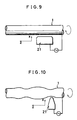
- Fig. 9 is a simplified side view showing a smoothing of the outer peripheral surface of a columnar workpiece by means of a tool-like electrode.
- Fig. 10 is a simplified side view showing a smoothing for shaping the outer peripheral surface of a workpiece symmetrically in rotation by means of a tool-like electrode.
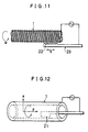
- Fig. 11 is a simplified side view showing a threading of a cylindrical workpiece by means of a sawtooth electrode.
- Fig. 12 is a simplified perspective view showing a smoothing of the inner peripheral surface of a cylindrical workpiece by means of a tool-like electrode.
- Fig. 13 is a simplified perspective view showing a smoothing for shaping the inner peripheral surface of a cylindrical workpiece symmetrically in rotation arbitrarily by means of a tool-like electrode.
- Fig. 14 is a simplified side view showing a gear cutting by means of a gear-toothed electrode.
- Fig. 15 is a simplified perspective view showing a transfer by means of a ring electrode as in the case of Fig. 8.
- Fig. 16 is a simplified perspective view showing a reshaping by means of a correction electrode.
- Fig. 17 is a simplified perspective view showing an arbitrary shaping by means of a rod electrode with a hemispherical surface on the nose.
- the invention comprises carrying out a strainless precision process through a radical reaction (free radical reaction) of a reactive radical (free radical) having an unpaired electron with atom or molecule constituting a workpiece.
- a plasma which can easily be produced by discharge at a degree of vacuum 1,3 mbar (1 Torr) or below [1,3.10 -3 to 1,3 mbar (10 -3 to 1 Torr)] will be utilized, however, since a density of the plasma thus produced is low and the working rate is slow, a high density plasma condition is generated for process by vibrating a charged corpuscle in a high frequency field under high pressure 1 bar. or over in the invention.
- the strainless precision process is carried out such that a workpiece of a brittle material hard to work such as silicon and germanium single crystal for manufacturing semiconductors, gallium-arsenic compound, various ceramics materials or the like is disposed in an atmospheric gas such as chlorine (Cl 2 ), fluorine (F 2 ) or the like, a high frequency voltage is impressed between a workpiece of conductor and an electrode of material relatively high in reaction temperature with a chloride gas such as tungsten (W), platinum (Pt) or the like which is disposed a little apart from the workpiece, a high frequency voltage is impressed between the aforementioned electrode and another electrode disposed in the vicinity of the work piece of insulator, a discharge is caused near the surface of the workpiece to generate a radical reactive chemically from the atmospheric gas, and in case, for example, silicon is used as the workpiece and a chloride gas is used as the gas, a radical reaction is caused on the surface of a working portion of the silicon to generate a silicon chloride, and the silicon chloride
- Fig. 1 illustrates the principle of a process of the invention, wherein a reference numeral 1 denotes a workpiece, 2 denotes a gas molecule, 3 denotes a radical (free radical), 4 denotes a constituent atom or molecule of the workpiece 1, and 5 denotes a compound.
- a reference numeral 1 denotes a workpiece
- 2 denotes a gas molecule
- 3 denotes a radical (free radical)
- 4 denotes a constituent atom or molecule of the workpiece 1
- 5 denotes a compound.
- the radical 3 is produced by subjecting the gas molecule 2 to a discharge near the surface of the workpiece 1 disposed in the atmospheric gas 2, the compound 5 capable of vaporizing at relatively low temperature is produced on reaction of the radical 3 with the constituent atom or molecule 4 of the workpiece 1, the compound 5 is vaporized by warming up the workpiece 1 to a set temperature relatively low or, for example, 200 °C or below on ordinary temperature or heater or the like (not indicated), thus removed from the working surface to form successively a space 6 of atom or molecule unit on the workpiece 1 to a macro recess, thus carrying out strainless cutting, boring, grooving and so forth.
- the radical reaction may also take place most probably at a small portion projecting from the surface of the workpiece 1, consequently the projecting portion is removed selectively to smoothing on atom or molecule level.
- Fig. 2 is a principle drawing of a device for strainless cutting by means of the radical 3 generated on a discharge of the workpiece 1, wherein a wire electrode 7 such as tungsten, platinum or the like is wound on feeding and take-up reels 8, 8 spaced apart from each other, the wire electrode 7 is laid apart a little from the workpiece 1 through a plurality of guide rollers 9, ... and in case the workpiece 1 is a conductor, a discharge is generated on a high frequency voltage impressed by a RF (high frequency) power (not indicated) between the workpiece 1 and the wire electrode 7 to activate the atmospheric gas 2 (not indicated), the space 6 is produced only in an area where the radical 3 is present as shown in Fig.
- a wire electrode 7 such as tungsten, platinum or the like is wound on feeding and take-up reels 8, 8 spaced apart from each other, the wire electrode 7 is laid apart a little from the workpiece 1 through a plurality of guide rollers 9, ... and in case the workpiece 1 is a conductor, a
- the wire electrode 7 normally uses a fine wire several ⁇ m to several ten ⁇ m in the precision process, therefore the reels 8 are rotated to have the wire wound on one side for feeding at all times, thereby preventing the wire electrode 7 from cutting due to a discharge at the identical portion. Further, the workpiece 1 and the wire electrode 7 are shifted relatively on computer control or other means available, and thus a radical reaction area is changed successively to cutting of the workpiece 1.
- Fig. 3 is a principle drawing of a device for smoothing the surface of the workpiece 1 by means of the radical 3 generated on discharge likewise, wherein a plane lapped electrode 11 is disposed in parallel and also at a small distance d over the plane workpiece 1 fixed on a surface plate 10, a high frequency voltage is impressed between the lapped electrode 11 and the workpiece 1 according to the workpiece 1 being a conductor or an insulator, a discharge is thus caused to generate the radical 3, thereby removing the constituent atom or molecule 4 of the workpiece 1.
- the discharge is generated selectively on a point effect between the lapped electrode 11 and the workpiece 1 at a salient 12 present on the surface of the workpiece 1, a removal of the constituent atom or molecule 4 on the radical reaction goes on at the portion, thus smoothing the surface of the workpiece 1.
- the distance d between the lapped electrode 11 and the workpiece 1 may be optimized for gap by gap sensor or the like, thereby enhancing a working efficiency, and further the lapped electrode 11 and the workpiece 1 can be shifted relatively so as to minimize a damage due to discharge of the lapped electrode 11 and also to work the surface as wide as possible.
- a curved surface of the workpiece 1 can also be smoothed by means of the lapped electrode 11 with a form according to the curved surface.
- the radical 3 is generated from exciting optically the atmospheric gas molecule 2 by laser beams 13 induced to a working portion of the workpiece 1, thereby realizing a strainless precision process.
- optical fibers 15 are buried in a disk wheel 14 radially and peripherally from the center, incident ports 16 of the laser beams 13 are formed intensively at the center, ejection ports 17, ...
- the laser beams 13 are thus ready for irradiating on the gas molecule 2 present near the surface of the workpiece 1 from a peripheral edge of the wheel 14 disposed orthogonally to the surface of the workpiece 1, and the compound 5 produced on a radical reaction of the radial 3 generated by the laser beams 13 with the constituent atom or molecule 4 of the workpiece 1 is removed accordingly, thereby realizing a strainless cutting or grooving.
- the incident ports 16 of the laser beams 13 are formed intensively on one side of a plane lap plate 18, the ejection ports 17, ...
- the incident ports 16 and the ejection ports 17, ... are coupled optically through the optical fibers 15, ... buried internally, the lap plate 18 is disposed a little apart from and in parallel with the workpiece 1, the laser beams 13 are irradiated to the gas molecule 2 near the surface of the workpiece 1, and thus the salient 12 present on the surface of the workpiece 1 is smoothed according to the radical reaction likewise.
- an ejection angle of the laser beams 13 from the ejection ports 17 is large, and since a power density of the laser beams 13 deteriorates according as the distance from the lap plate 18 gets large, the constituent atom or molecule 4 at the salient 12 which is nearest to the lap plate 18 is removed, and thus the salient 12 is smoothed selectively as a result. Then, a continuous process may be realized likewise by shifting the wheel 14 or the lap plate 18 and the workpiece 1 relatively, and the wheel 14 is rotated to change a position for irradiating the laser beams 13 continuously, thereby obtaining an exceedingly uniform working plane.
- a process on radical reaction for which an optical excitation of the laser beams 13 is utilized can be applied to various properties of the workpiece 1 irrespective of conductor or insulator. Further, for boring and grooving, a strainless precision process may be realized likewise according to a home position irradiation and scanning of focused laser beams.
- Fig. 6 represents a cutting method as in the case of Fig. 2, wherein the wire electrode 7 disposed in parallel with the plane workpiece 1 is delivered in the direction X, the wire electrode 7 and the workpiece 1 are shifted relatively in the direction Z to cut the workpiece 1, and further shifted in the direction Y to cut or groove a new portion. Then, the cut face is flattened according to a linearity of the laid wire electrode 7.
- Fig. 7 represents a method for boring the workpiece 1 by shifting needle electrode 19 kept orthogonal to the workpiece 1 with its tip disposed to come near thereto in the direction Z, and a method for grooving by shifting the needle electrode 19 or the workpiece 1 in the directions X and Y is further represented therein.
- Fig. 8 represents a working method or transferring method for forming a recess same in sectional form as a prismatic electrode 20 on the workpiece 1 by keeping the prismatic electrode 20 (triangular prism as indicated) having a predetermined sectional form orthogonal to the workpiece 1 and shifting it in the direction Z.
- Fig. 9 to Fig. 11 represent a method for working the outer peripheral surface from rotating the workpiece 1 with a symmetrical form in rotation.
- Fig. 9 represents a method wherein a tool-like electrode 21 having a plane is disposed near the outer periphery of the cylindrical workpiece 1 in parallel therewith, the workpiece 1 is rotated, the tool-like electrode 21 is shifted axially or in the direction Z and further shifted in the direction X to have the interval adjusted accordingly, thus smoothing the outer peripheral surface of the workpiece 1
- Fig. 10 represents a method wherein the outer peripheral surface of the workpiece 1 is smoothed likewise to an arbitrary symmetrical form in rotation by means of the tool-like electrode 21 with the nose almost pointed, and further Fig.
- 11 represents a method wherein a saw-tooth electrode 23 having projections 22, ... arranged at regular intervals linearly is shifted axially at a velocity v in tune with a rotational angle speed ⁇ of the workpiece 1, thereby threading the outer periphery of the workpiece 1.
- Fig. 12 and Fig. 13 represent a method for working the inner peripheral surface from rotating the hollow workpiece 1 with a symmetrical form in rotation.
- Fig. 12 represents a method wherein the tool-like electrode 21 having a plane is disposed near the inner peripheral surface of the hollow cylindrical workpiece 1 in parallel therewith, the workpiece 1 is rotated, the tool-like electrode 21 is shifted axially or in the direction Z and further shifted in the direction X to have the interval adjusted accordingly, thus smoothing the inner peripheral surface of the workpiece 1, and
- Fig. 13 represents a method wherein the inner peripheral surface of the workpiece 1 is smoothed likewise to an arbitrary symmetrical form in rotation by means of the tool-like electrode 21 with the nose almost pointed.
- Fig. 14 represents a method wherein a gear-toothed electrode 25 having projections 24, ... arranged at regular intervals on the outer periphery of a disk and the disk workpiece 1 are disposed with each outer periphery coming near and each shaft kept in the same direction, the gear-toothed electrode 25 is rotated in one direction at an angular velocity ⁇ 1 , and the workpiece 1 is rotated reversely at an angular velocity ⁇ 2 , thereby carrying out a gear-cutting on the outer periphery of the workpiece 1.
- a circular pitch of the gear teeth formed on the workpiece 1 can be set properly by adjusting the angular velocities ⁇ 1 and ⁇ 2 .
- Fig. 15 represents a transfer similar to the working method shown in Fig. 8, wherein the cylindrical or prismatic workpiece 1 disposed within a ring electrode 27 with a proper shape of tongued-and-grooved face 26 necessary for working formed on the inner periphery is shifted axially, and thus a shape of the tongued-and-grooved face 26 is transferred axially on the outer peripheral surface of the workpiece 1, thereby transferring a sectional form of the ring electrode 27 to the workpiece 1.
- Fig. 16 represents a method for reshaping a working face entirely as working a predetermined margin only at each point on the working face of the workpiece 1 by means of a correction electrode 28 having shape and size capable of correcting a local shape of the workpiece 1 on the nose. Then, the process corresponds to a process such as end milling or the like in a conventional milling.
- Fig. 17 represents a method for working the workpiece 1 to a complicate shape by means of a rod electrode 29 with a hemispherical nose.
- the process corresponds to a conventional ball milling or the like.
- the invention comprises removing and so working the workpiece 1 on an atom or molecule level by the radical 3 generated in the atmospheric gas 2 through discharge or laser beam excitation, and an optimum condition must be set according to a material and area to work of the workpiece 1.
- a working is carried out on discharge, where pressure of the atmospheric gas 2 is low, the working may proceed slowly in a large area as the discharge covers an extensive range, which is suitable to smoothing, but where the pressure is high, the working may proceed efficiently and locally as the discharge is limited and thus the radical 3 may be generated at high probability, which is suitable to cutting by the wire electrode 7 and also to boring by the needle electrode 19.
- the atmospheric gas 2 optimized to a material of the workpiece 1 must be selected, and further it is necessary to heat the workpiece 1 to such temperature as will not cause a thermal denaturation according to temperature easy to cause a radical reaction of the generated radical 3 with the constituent atom or molecule 4 and also to a vaporization temperature of the compound 5 produced on the radical reaction.
- chloride gas is employed normally as the atmospheric gas 2, a radical reaction is caused at relatively low temperature, a sublimable silicon chloride is produced, and the silicon chloride can be vaporized at ordinary temperature or at 200 °C or below.
- a gas is activated selectively on discharge in the vicinity of a workpiece disposed in a gaseous atmosphere, a compound produced on a radical reaction with a constituent atom or molecule of the workpiece is vaporized, therefore a working contactless in principle may be effected, and hence a strainless process totally freee from residual defect and thermally affected layer such as crack and the like which cannot be avoided with the prior art process using a brittle fracture by fine cracks and thus deteriorate a reliability of the working face most probably may be realized, a reliability of products can sharply be enhanced, and since the process comprises removing the workpiece on a constituent atom or molecule level, an exceedingly fine portion can be processed in precision simply in principle, and further the workpiece will never be damaged, therefore an after-treatment whereby a cut face is removed by 100 ⁇ m or over in thickness hitherto is no more required, and thus not only the post-process is so simplified, but also materials can be utilized effectively.
- strainless precision process is so efficient as described above, it is quite simple that a reactive radical is generated by activating selectively a gas in the vicinity of the working portion of a workpiece disposed in a gaseous atmosphere through discharge or laser beam excitation, a compound produced on a radical reaction of the radical with an atom or molecule constituting the workpiece is vaporized spontaneously or by heating not to denature the workpiece and then removed from the working portion, thereby realizing a precision process such as strainless cutting, smoothing, boring, grooving and so forth.
Landscapes
- Chemical & Material Sciences (AREA)
- Engineering & Computer Science (AREA)
- Crystallography & Structural Chemistry (AREA)
- Materials Engineering (AREA)
- Metallurgy (AREA)
- Organic Chemistry (AREA)
- Mechanical Engineering (AREA)
- Electrical Discharge Machining, Electrochemical Machining, And Combined Machining (AREA)
Claims (9)
- Spannungsfreies Präzisionsverfahren durch eine Radikalreaktion, wobeieine Elektrode mit einer gemäß einem Bearbeitungsverfahren vorgegebenen Form geringfügig beabstandet von einem Werkstück (1) angeordnet ist, das in einer gasförmigen Atmosphäre (2) mit einem Druck von 1 Bar oder mehr angeordnet ist;der Elektrode eine Hochfrequenzspannung aufgedrückt wird;freie Radikale (3) durch Aktivieren von Gas (2) in einem in der Nähe der Elektrode erzeugten hochfrequenten elektrischen Feld erzeugt werden; undeine durch eine Radikalreaktion zwischen Radikalen (3) des aktivierten Gases (2) und Atomen oder Molekülen (4), die das Werkstück (1) bilden, erzeugte Verbindung (5) verdampft wird, wodurch das Werkstück (1), das bezüglich der Elektrode verschoben wird, bearbeitet wird.
- Verfahren nach Anspruch 1, wobei eine Drahtelektrode (7) als Elektrode verwendet wird, wodurch das Werkstück (1) geschnitten wird.
- Verfahren nach Anspruch 1, wobei eine Läppelektrode (11) mit einer flachen oder mit einer gekrümmten Oberfläche als Elektrode verwendet wird, um das Werkstück (1) zu glätten.
- Verfahren nach Anspruch 1, wobei eine orthogonal zum Werkstück (1) gehaltene Nadelelektrode (19) als Elektrode verwendet wird, um das Werkstück (1) zu bohren.
- Verfahren nach Anspruch 1, wobei eine Prismaelektrode (20) oder eine Ringelektrode (27) mit einer vorgegebenen Querschnittsform als Elektrode verwendet wird, um die Form auf das Werkstück (1) zu übertragen.
- Verfahren nach Anspruch 1, wobei eine werkzeugartige Elektrode (21) als Elektrode verwendet wird, das Werkstück (1) gedreht und die werkzeugartige Elektrode (21) axial verschoben wird, um das Werkstück (1) rotationssymmetrisch zu glätten.
- Verfahren nach Anspruch 1, wobei eine sägezahnförmige Elektrode (23) mit darauf linear in gleichmäßigen Intervallen angeordneten Vorsprüngen (22) als Elektrode verwendet wird, das rotationssymmetrische Werkstück (1) gedreht wird und das Werkstück (1) und die Elektrode (23) axial relativ zueinander verschoben werden, um auf dem Werkstück (1) ein Gewinde auszubilden.
- Verfahren nach Anspruch 1, wobei eine gezahnte Elektrode (25) mit am Außenumfang einer Scheibe in regelmäßigen Intervallen angeordneten Vorsprüngen (24) als Elektrode verwendet wird, wobei das scheibenförmige Werkstück (1) und die gezahnte Elektrode (25) entgegengesetzt zueinander gedreht werden, wodurch das Werkstück (1) einer Zahnformung unterzogen wird.
- Verfahren nach Anspruch 1, wobei eine Stabelektrode (29) mit einer halbkugelförmigen Spitze als Elektrode verwendet wird, um das Werkstück (1) in eine beliebige Form zu bearbeiten.
Applications Claiming Priority (2)
| Application Number | Priority Date | Filing Date | Title |
|---|---|---|---|
| JP16076087 | 1987-06-26 | ||
| JP160760/87 | 1987-06-26 |
Publications (4)
| Publication Number | Publication Date |
|---|---|
| EP0300224A2 EP0300224A2 (de) | 1989-01-25 |
| EP0300224A3 EP0300224A3 (en) | 1990-11-28 |
| EP0300224B1 EP0300224B1 (de) | 1993-12-08 |
| EP0300224B2 true EP0300224B2 (de) | 1998-09-30 |
Family
ID=15721874
Family Applications (1)
| Application Number | Title | Priority Date | Filing Date |
|---|---|---|---|
| EP88110108A Expired - Lifetime EP0300224B2 (de) | 1987-06-26 | 1988-06-24 | Präzises spannungsfreies Nachbehandlungsverfahren durch Radikalreaktionen |
Country Status (3)
| Country | Link |
|---|---|
| US (1) | US4960495A (de) |
| EP (1) | EP0300224B2 (de) |
| DE (1) | DE3886113T3 (de) |
Families Citing this family (7)
| Publication number | Priority date | Publication date | Assignee | Title |
|---|---|---|---|---|
| US5397420A (en) * | 1991-03-03 | 1995-03-14 | Nippondenso Co., Ltd. | Fine structure forming device |
| FR2685127B1 (fr) * | 1991-12-13 | 1994-02-04 | Christian Licoppe | Photonanographe a gaz pour la fabrication et l'analyse optique de motifs a l'echelle nanometrique. |
| DE19518270C1 (de) * | 1995-05-18 | 1996-08-22 | Fraunhofer Ges Forschung | Rutschfester Fußbodenbelag und Verfahren zu seiner Herstellung |
| JP3069271B2 (ja) * | 1995-07-12 | 2000-07-24 | 勇藏 森 | 回転電極を用いた高密度ラジカル反応による高能率加工方法及びその装置 |
| JPH09272119A (ja) * | 1996-04-04 | 1997-10-21 | Daido Hoxan Inc | ウエハの製法およびそれに用いる装置 |
| US6165688A (en) * | 1996-05-15 | 2000-12-26 | The United States Of America, As Represented By The Secretary Of Commerce | Method of fabricating of structures by metastable atom impact desorption of a passivating layer |
| DE102015119325A1 (de) | 2015-11-10 | 2017-05-11 | Leibniz-Institut für Oberflächenmodifizierung e.V. | Verfahren zur Glättung von Oberflächen eines Werkstücks |
Family Cites Families (15)
| Publication number | Priority date | Publication date | Assignee | Title |
|---|---|---|---|---|
| DE3029792A1 (de) * | 1980-08-06 | 1982-03-11 | Siemens AG, 1000 Berlin und 8000 München | Verfahren zum zerteilen eines halbleiterkristalls in scheiben |
| EP0061906B1 (de) * | 1981-03-26 | 1987-06-10 | Inoue-Japax Research Incorporated | Verfahren und Vorrichtung zur Bearbeitung eines Werkstückes mit energiereichen Teilchen und ein auf diese Weise bearbeitetes Produkt |
| GB2106541B (en) * | 1981-06-24 | 1984-11-21 | Ohyo Jiki Lab Co Ltd | Electrolytic and electric discharge machining of electrically non-conductive workpieces |
| US4411733A (en) * | 1982-06-18 | 1983-10-25 | Bell Telephone Laboratories, Incorporated | SPER Device for material working |
| DE3477590D1 (en) * | 1983-05-30 | 1989-05-11 | Inoue Japax Res | Method of and apparatus for machining ceramic materials |
| JPH0622212B2 (ja) * | 1983-05-31 | 1994-03-23 | 株式会社東芝 | ドライエッチング方法 |
| JPS6074626A (ja) * | 1983-09-30 | 1985-04-26 | Fujitsu Ltd | ウエハー処理方法及び装置 |
| KR920004171B1 (ko) * | 1984-07-11 | 1992-05-30 | 가부시기가이샤 히다찌세이사꾸쇼 | 드라이에칭장치 |
| US4624736A (en) * | 1984-07-24 | 1986-11-25 | The United States Of America As Represented By The United States Department Of Energy | Laser/plasma chemical processing of substrates |
| JPS63500442A (ja) * | 1985-08-08 | 1988-02-18 | ラビアン・ラスツロ | ハイポイドギヤ等の歯形を有するテ−パギヤの放電加工又は電気化学的加工方法 |
| US4749440A (en) * | 1985-08-28 | 1988-06-07 | Fsi Corporation | Gaseous process and apparatus for removing films from substrates |
| US4751779A (en) * | 1986-04-02 | 1988-06-21 | Ds Scanner Co., Ltd. | Method of producing a core for magnetic head |
| US4713141A (en) * | 1986-09-22 | 1987-12-15 | Intel Corporation | Anisotropic plasma etching of tungsten |
| US4687539A (en) * | 1986-10-29 | 1987-08-18 | International Business Machines Corp. | End point detection and control of laser induced dry chemical etching |
| JPS63147327A (ja) * | 1986-12-10 | 1988-06-20 | Dainippon Screen Mfg Co Ltd | 表面処理における処理終点検知方法 |
-
1988
- 1988-06-24 EP EP88110108A patent/EP0300224B2/de not_active Expired - Lifetime
- 1988-06-24 DE DE3886113T patent/DE3886113T3/de not_active Expired - Fee Related
- 1988-06-24 US US07/211,184 patent/US4960495A/en not_active Expired - Lifetime
Also Published As
| Publication number | Publication date |
|---|---|
| EP0300224A3 (en) | 1990-11-28 |
| DE3886113T3 (de) | 1999-04-01 |
| EP0300224B1 (de) | 1993-12-08 |
| DE3886113D1 (de) | 1994-01-20 |
| DE3886113T2 (de) | 1994-06-30 |
| EP0300224A2 (de) | 1989-01-25 |
| US4960495A (en) | 1990-10-02 |
Similar Documents
| Publication | Publication Date | Title |
|---|---|---|
| US12327768B2 (en) | Substrate processing system and substrate processing method | |
| US20210242010A1 (en) | Substrate processing system and substrate processing method | |
| CN2893917Y (zh) | 具有粘附处理残余物的表面的构件及包括其的衬底处理室 | |
| JP6348725B2 (ja) | プラズマ処理装置の硬質脆性構成要素のための延性モード機械加工方法 | |
| US5458827A (en) | Method of polishing and figuring diamond and other superhard material surfaces | |
| US20070215463A1 (en) | Pre-conditioning a sputtering target prior to sputtering | |
| JP7547105B2 (ja) | Si基板生成方法 | |
| Windholz et al. | Nanosecond pulsed excimer laser machining of chemical vapour deposited diamond and highly oriented pyrolytic graphite: Part I An experimental investigation | |
| JPH0931670A (ja) | 回転電極を用いた高密度ラジカル反応による高能率加工方法及びその装置 | |
| JP2521127B2 (ja) | ラジカル反応による無歪精密加工方法 | |
| EP0300224B2 (de) | Präzises spannungsfreies Nachbehandlungsverfahren durch Radikalreaktionen | |
| US5792254A (en) | Production of diamond film | |
| CN108350604B (zh) | 用于制造半导体层的方法和装置 | |
| JP2011192687A (ja) | 半導体基板の加工装置、半導体基板の製造方法、及び半導体基板 | |
| JPH05110206A (ja) | 半導体発光素子の製造方法及びその製造装置 | |
| US20050211922A1 (en) | Minute three dimensional structure producing apparatus and method | |
| US11077525B2 (en) | Method of processing a silicon carbide containing crystalline substrate, silicon carbide chip, and processing chamber | |
| US10475689B2 (en) | Method for processing a holding plate, in particular for a clamp for holding a wafer | |
| JPH07232319A (ja) | インゴットのスライス方法 | |
| JP2004063883A (ja) | 半導体ウェーハの製造方法 | |
| JPH0519978B2 (de) | ||
| JP7174850B2 (ja) | 材料のワークピースを剪断するための方法およびシステム | |
| WO2011046052A1 (ja) | 電極板の通気孔形成方法 | |
| JPH04331800A (ja) | ダイヤモンド表面の平滑化方法及び装置並びにそれを利用したダイヤモンド製品 | |
| JP3189201B2 (ja) | 太陽電池製造装置およびそれを用いた太陽電池の製造方法 |
Legal Events
| Date | Code | Title | Description |
|---|---|---|---|
| PUAI | Public reference made under article 153(3) epc to a published international application that has entered the european phase |
Free format text: ORIGINAL CODE: 0009012 |
|
| AK | Designated contracting states |
Kind code of ref document: A2 Designated state(s): DE FR GB |
|
| PUAL | Search report despatched |
Free format text: ORIGINAL CODE: 0009013 |
|
| AK | Designated contracting states |
Kind code of ref document: A3 Designated state(s): DE FR GB |
|
| 17P | Request for examination filed |
Effective date: 19901228 |
|
| RAP1 | Party data changed (applicant data changed or rights of an application transferred) |
Owner name: MORI, YUZO Owner name: UHA MIKAKUTO PRECISION ENGINEERING RESEARCH INSTI |
|
| 17Q | First examination report despatched |
Effective date: 19920225 |
|
| GRAA | (expected) grant |
Free format text: ORIGINAL CODE: 0009210 |
|
| AK | Designated contracting states |
Kind code of ref document: B1 Designated state(s): DE FR GB |
|
| REF | Corresponds to: |
Ref document number: 3886113 Country of ref document: DE Date of ref document: 19940120 |
|
| ET | Fr: translation filed | ||
| PLBI | Opposition filed |
Free format text: ORIGINAL CODE: 0009260 |
|
| 26 | Opposition filed |
Opponent name: SUMINO, SHIN Effective date: 19940908 |
|
| PLAW | Interlocutory decision in opposition |
Free format text: ORIGINAL CODE: EPIDOS IDOP |
|
| PLAW | Interlocutory decision in opposition |
Free format text: ORIGINAL CODE: EPIDOS IDOP |
|
| PLAW | Interlocutory decision in opposition |
Free format text: ORIGINAL CODE: EPIDOS IDOP |
|
| PUAH | Patent maintained in amended form |
Free format text: ORIGINAL CODE: 0009272 |
|
| STAA | Information on the status of an ep patent application or granted ep patent |
Free format text: STATUS: PATENT MAINTAINED AS AMENDED |
|
| 27A | Patent maintained in amended form |
Effective date: 19980930 |
|
| AK | Designated contracting states |
Kind code of ref document: B2 Designated state(s): DE FR GB |
|
| ET3 | Fr: translation filed ** decision concerning opposition | ||
| REG | Reference to a national code |
Ref country code: GB Ref legal event code: IF02 |
|
| PGFP | Annual fee paid to national office [announced via postgrant information from national office to epo] |
Ref country code: FR Payment date: 20050621 Year of fee payment: 18 |
|
| PGFP | Annual fee paid to national office [announced via postgrant information from national office to epo] |
Ref country code: GB Payment date: 20060614 Year of fee payment: 19 |
|
| PGFP | Annual fee paid to national office [announced via postgrant information from national office to epo] |
Ref country code: DE Payment date: 20060728 Year of fee payment: 19 |
|
| GBPC | Gb: european patent ceased through non-payment of renewal fee |
Effective date: 20070624 |
|
| REG | Reference to a national code |
Ref country code: FR Ref legal event code: ST Effective date: 20080229 |
|
| PG25 | Lapsed in a contracting state [announced via postgrant information from national office to epo] |
Ref country code: DE Free format text: LAPSE BECAUSE OF NON-PAYMENT OF DUE FEES Effective date: 20080101 |
|
| PG25 | Lapsed in a contracting state [announced via postgrant information from national office to epo] |
Ref country code: GB Free format text: LAPSE BECAUSE OF NON-PAYMENT OF DUE FEES Effective date: 20070624 |
|
| PG25 | Lapsed in a contracting state [announced via postgrant information from national office to epo] |
Ref country code: FR Free format text: LAPSE BECAUSE OF NON-PAYMENT OF DUE FEES Effective date: 20070702 |
|
| PG25 | Lapsed in a contracting state [announced via postgrant information from national office to epo] |
Ref country code: FR Free format text: LAPSE BECAUSE OF NON-PAYMENT OF DUE FEES Effective date: 20060630 |