EP0299403B1 - Verfahren und Gerät zum Bewegen eines Werkzeuges entlang einer gekrümmten Bahn - Google Patents
Verfahren und Gerät zum Bewegen eines Werkzeuges entlang einer gekrümmten Bahn Download PDFInfo
- Publication number
- EP0299403B1 EP0299403B1 EP88111040A EP88111040A EP0299403B1 EP 0299403 B1 EP0299403 B1 EP 0299403B1 EP 88111040 A EP88111040 A EP 88111040A EP 88111040 A EP88111040 A EP 88111040A EP 0299403 B1 EP0299403 B1 EP 0299403B1
- Authority
- EP
- European Patent Office
- Prior art keywords
- arc
- signals
- workpoint
- orientation
- wrist
- Prior art date
- Legal status (The legal status is an assumption and is not a legal conclusion. Google has not performed a legal analysis and makes no representation as to the accuracy of the status listed.)
- Expired
Links
Images


Classifications
-
- G—PHYSICS
- G05—CONTROLLING; REGULATING
- G05B—CONTROL OR REGULATING SYSTEMS IN GENERAL; FUNCTIONAL ELEMENTS OF SUCH SYSTEMS; MONITORING OR TESTING ARRANGEMENTS FOR SUCH SYSTEMS OR ELEMENTS
- G05B19/00—Programme-control systems
- G05B19/02—Programme-control systems electric
- G05B19/18—Numerical control [NC], i.e. automatically operating machines, in particular machine tools, e.g. in a manufacturing environment, so as to execute positioning, movement or co-ordinated operations by means of programme data in numerical form
- G05B19/41—Numerical control [NC], i.e. automatically operating machines, in particular machine tools, e.g. in a manufacturing environment, so as to execute positioning, movement or co-ordinated operations by means of programme data in numerical form characterised by interpolation, e.g. the computation of intermediate points between programmed end points to define the path to be followed and the rate of travel along that path
-
- G—PHYSICS
- G05—CONTROLLING; REGULATING
- G05B—CONTROL OR REGULATING SYSTEMS IN GENERAL; FUNCTIONAL ELEMENTS OF SUCH SYSTEMS; MONITORING OR TESTING ARRANGEMENTS FOR SUCH SYSTEMS OR ELEMENTS
- G05B2219/00—Program-control systems
- G05B2219/30—Nc systems
- G05B2219/45—Nc applications
- G05B2219/45104—Lasrobot, welding robot
Definitions
- This invention relates generally to the field of controlled path motion for manipulators.
- Such manipulators may carry a tool, such as a welding electrode requiring manipulation to a series of points along a workpiece.
- a typical manipulator of that type may be constructed as generally described in Holmes et al U.S. Patent 4,598,380.
- Such a manipulator may be computer controlled to move a tool along straight line paths between a series of reference points, the coordinates of which are input to the computer during a teaching phase.
- Teaching of the reference points may be carried out as generally taught by Corwin, Jr. et al U.S. Patent 3,920,972, and path control may be carried out as taught in Hohn U.S. Patent 3,909,600 or in Magnuson U.S. Patent 4,506,335.
- EP-A-144 442 discloses a technique for control of a manipulator to effect motion of a tool along an arc wherein the angle of the tool is controlled in response to taught tool orientations at a plurality of points around the arc.
- this document discloses a method for controlling motion of a function element carried by a manipulator and having associated therewith a workpoint, the motion being described by a two-dimensional arc defining a path to be traversed by the workpoint and by a velocity of the workpoint, the arc being defined by input signals representing coordinates of three reference positions on the arc including the arc end positions, the velocity of the workpoint being defined by further input signals, the manipulator including movable members for effecting motion of the function element and a servomechanism circuit for controlling the motion of the movable members, the motion being effected by: (i) periodically producing arc intermediate position signals representing coordinates of intermediate positions along the arc; and, (ii) producing machine-coordinate signals for control of the servomechanism circuit in response to the intermediate position signals, the machine coordinate signals defining the motion of said movable members between their positions at the current location of the workpoint and the location of the workpoint defined by next intermediate position.
- this control determines the locations of the tool tip and tool base at each of three taught locations. From this information the control determines the included angle for both the tool tip and tool base arcs and interpolates intermediate angular increments according to the ratio of the included angles. The tool inclination vector is determined at each intermediate point and the tool inclination vector and tool centrepoint coordinates are used to determine the machine coordinates. While this reference provides a technique for maintaining a desired tool vector orientation around an arcuate path, nothing in this reference teaches or suggests any technique for effecting the arcuate motion in a plane not parrallel to horizontal or vertical planes.
- the present invention provides an improved method of moving a tool tip along a curved path.
- the method may be practiced in a tool positioning system comprising a face plate for supporting a tool, wrist means for rotatably supporting the face plate, arm means for movably supporting the wrist means, servo means responsive to movement commands and rotation commands for causing controlled movement of the wrist means and controlled rotation of the face plate, and means for generating the movement commands and the rotation commands, in response to input signals representing the location of three reference positions on the curved path together with a desired tool attitude relative to the path at each reference position.
- the method uses information defining the shape of the curved path, the position of the tool centerpoint or workpoint and orientation of the wrist at three reference positions along the path, and desired attitude of the tool relative to the path to calculate and store the coordinates of the tool centerpoint and the orientation angles of the wrist for intermediate positions on the curved path.
- the machine advances the tool centerpoint on straight line paths between these intermediate positions while linearly interpolating the change in tool attitude to generate movement commands for the manipulator axes.
- a planar circular arc is chosen as the curved path.
- a teaching means is operated to position and orient the tool at three reference positions along that arc. At each reference position, the tool orientation is dictated by a desired line of approach described by the process angles.
- the method may comprise the steps of computing the coordinates of the centerpoint of a circle defined by the arc, calculating arc angles for each of the work points and iteratively using those arc angles for calculation of the coordinates of the work points.
- the desired process angles may be calculated by linear interpolation between the reference process angles.
- manipulator For purposes of illustrating the present invention, a manipulator shown in the accompanying drawings shall be described in detail.
- the illustrated manipulator corresponds to one manufactured by Cincinnati Milacron Inc., the assignee of the present invention. While the detailed description of the preferred embodiment shall necessarily reflect the actual implementation, such details should not be construed as limitations on the present invention which is defined by the appended claims.
- a manipulator 10 is shown carrying a tool 50 and connected to a control 60.
- the manipulator is constructed so that the motion of its members describe axes of rotation.
- the first of these axes is called the base axis and is defined by rotation of the plate 16 about a vertical axis through its centre.
- An upper arm 18 rotates about a horizontal axis, called the shoulder axis, through the centre of pivot 20 intersecting the vertical axis of rotation of the base.
- a forearm 22 rotates about a horizontal axes called the elbow axis, through the pivot 24.
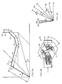
- wrist 32 Mounted at the end of forearm 22 is wrist 32 which provides three additional axes of rotation as best illustrated in Figure 3 b .
- the first of these is rotation of an inner segment 33 about an axis lying parallel to or coincident with the longitudinal centre line of forearm 22; the second is rotation of an outer segment 31 about an axis perpendicular to the slice separating inner segment 33 from outer segment 31, and the third is rotation of face plate 44 about an axis orthogonal thereto and through its centre.
- Rotations of members about the base, shoulder, and elbow axes are sufficient to define locations within the operating volume of the manipulator of a tool centerpoint 48 associated with the tool 50.
- Rotations of the inner and outer segments of the wrist 32 and the face plate 44 control orientations of the tool at the programmed locations in accordance with programmed orientation angles.
- Each of the six axes of motion is servo controlled by connection of command and feedback signals to a servo control 64 of the control 60.
- Operation of the tool 50 is accomplished by machine interface 66 which responds to the programmed cycle of operation controlled by the cycle control 62.
- the cycle control 62 operates upon stored location, orientation, velocity, tool dimension and function data to produce control signals for the servo control 64 and the machine interface 66.
- the tool 50 is a welding torch, and control of the welding process is effected through the machine interface in response to stored function signals.
- Other tools for joining, cutting, cleaning, polishing, grasping, and so forth may be substituted for the torch shown and controlled through the machine interface 66.
- Rotations of the upper arm and forearm about their respective axes are achieved by the linear motion of screws 30 and 25 through nuts 28 and 26. Rotation of the nuts is imparted through pulleys 29 and 27 respectively by drive motors not shown.
- Rotation of the plate 16 about its axis is accomplished through a transmission 15 driving a pinion 13 which in turn drives a ring gear 17 mounted to the plate 16.
- the drive to transmission 15 is provided by a motor 14.
- Rotation of the axes of the wrist 32 is accomplished through concentric torque tubes, not shown, within forearm 22 driven by motors 34, 36, and 38 through transmission 40.
- Position signals for each movable member are produced by position transducers, such as resolvers, which may be mechanically driven by motion of the machine member or by the drive motor of the machine member.
- Cycle control 62 includes microprocessor 72 and interrupt control 74 both tied directly to the system bus 80.
- Operating system programs executed by microprocessor 72 are stored in memory 76 and include the programs identified as mode control 82, auto mode 84 and teach mode 86. Data defining the user specified locations, velocities and functions are stored in data store 78.
- Memory 76 is connected directly to system bus 80.
- the set of programs identified as auto mode 84 are used by microprocessor 72 to execute the cycle of operation defined by the data stored in data store 78. Execution of the auto mode programs is carried out by microprocessor 72 independently until execution is interrupted by an interrupt signal processed by interrupt control 74.
- a math processor 63 with its associated microprocessor 73 and memory 75 is connected to the system bus 80 for performing interpolations of intermediate points on a circular arc between the reference locations as hereinafter described. Straight line interpolation, however, is performed by cylce control 62. It is to be understood that the operations performed by the math processor 63 could be performed by the cycle control 62, provided that the cycle control processor 72 had sufficient capacity and operating speed to complete all computations at a rate suitable for real-time control of motion of manipulator 10.
- Servo control 64 includes the servo supervisor 90 which preprocesses servo command signals produced by cycle control 62 and the servo input/output modules 92, 94, and 96 associated with the actual control of the manipulator axis drive motors.
- the servo supervisor 90 includes a microprocessor 100, a programmable timer 102, and local memory 104 including the servo control process programs 105.
- Servo interrupt signals are periodically produced by the programmable timer 102. The period between interrupt signals defines the interval of each iteration of the path control procedures executed by the cycle control.
- the servo supervisor 90 receives machine axes command signals representing increments of motion of the manipulator members relative to their axes of rotation to be effected during the iteration interval.
- These machine axis command signals are processed by the servo supervisor 90 to produce servo command signals defining subincrements for each of the machine axes effective for sub-divisions of the iteration interval.
- the servo command signals are distributed to the servo input/output modules 92, 94, and 96 at predefined sub-intervals of the iteration interval.
- the servo input/output modules 92, 94, and 96 use the servo command signals and feedback signals produced by position transducers to control the machine axes drive motors.
- the block diagram of the servo input/output module 92 is representative of the interconnection of elements of the servo input/output modules 94, and 96. Data is transferred to and from the module from the system bus 80 through the dual port device 118.
- the module includes a local bus 116 interconnecting a microprocessor 106 with the dual port device 118, a local memory 112, the drive interface circuitry 110, and the machine axis position measuring transducer interface 108.
- the microprocessor 106 controls two machine axis drive motors, such as motors 124 and 126 in response to the servo command signals and the feedback signals according to the servo input/output program 114 stored in memory 112.
- Each machine axis servo command signal is compared to the corresponding current position signal as defined by one of the position transducers 120, 122 to produce a position error signal which is then applied to the drive interface circuitry 110 to produce a drive control signal for application to the associated machine axis drive motor.
- each servo I/O module controls two machine drive axes
- the blocks 128, 130 and 131 are understood to each represent two pairs of resolvers and drive motors.
- Servo command signals represent increments of machine axis motion to be effected within a few milliseconds.
- the machine axis command signals represent increments of machine member motion to be effected within the iteration interval of 10 to 20 milliseconds.
- cycle control 62 controls the execution of functions represented by input signals and associated with programmed locations.
- Function commands are stored with the program data in data store 78 and are executed in accordance with function execution sub-routines associated with the auto mode programs 84.
- Control of machine functions is effected through input/output devices, such as limit switches, push buttons, relays and solenoids.
- the machine input/output devices are directly controlled by the device I/O module 132 in cooperation with the machine input/output interface circuitry 150.
- Data is transferred to and from the system bus 80 through the dual port device 146.
- the dual port device 146 is connected to the local bus 144 of the device input/output control module 132. Operation of the module is controlled by the local microprocessor 134 connected to bus 144 which executes programs stored in the local memory 140.
- connection of the machine input/output interface circuitry 150 to module 132 is accomplished through a serial interface circuit 136.
- a control cabinet operator panel 148 is connected by parallel lines to a parallel interface circuit 138.
- Monitoring and control of the interface circuits 138 and 136 are accomplished by the microprocessor 134 in response to respectively the control I/O program 141 and the machine I/O program 142 stored in local memory 140.
- Current conditions of machine input/output devices are reflected in device status signals transferred from the device I/O module 132 through the dual port device 146 to the cycle control 62.
- Function command signals produced by cycle control 62 in accordance with the stored program of operation are transferred over system bus 80 through dual port device 146 and ultimately to the appropriate machine input/output interface device by the serial interface 136.
- the control permits exchange of data through the data input/output module 152 and its associated interfaces. While the cycle control 62 is operating under the auto mode programs 84, location data may be exchanged in response to function commands. This in-process data exchange takes place between an in-process data transceiver 174 and the control 60 through the data I/O module 152. Location data from data store 78 is transferred from system bus 80 to the data I/O module through its dual port device 166. The data I/O module microprocessor 154 operating under control of the in-process transceiver I/O program 162 stored in its local memory 158 transfers the location data from dual port device 166 to the serial channel interface 156 for transmission to the in-process data transceiver 174. In reverse, data from the in-process data transceiver 174 is input to the serial channel interface 156 and transferred therefrom on the local bus 164 to the dual port device 166. From there data is available to the cycle control 62 on the system bus 80.
- program data may be exchanged between the data store 78 of memory 76 and a bulk data store through a bulk data transceiver 172 or to a data terminal 170.
- Examples of a bulk data store include serial tape and data disk devices.
- a data terminal 170 may be used to display and modify program data for restorage after modification.
- data is exchanged by the data I/O module microprocessor 154 operating in response to the appropriate program set such as, for example, the data terminal I/O program 160 or the bulk data transceiver I/O,program 161.
- Data is transferred to and from the external device through the serial data interface 156 to the local bus 164 and through the dual port device 166 connected to system bus 80.
- the teach pendant 68 is associated with the execution of teach mode programs 86 by the cycle control 62.
- Location and function data defining a programmed cycle of operation may be generated by an operator using the teach pendant 68.
- This pendant permits manual operation of manipulator 10 and the storage of location and function data in data store 78.
- data is transferred to and from pendant 68 through the serial channel interface 156 to local bus 164 and therefrom through the dual port device 166 to the system bus 80.
- the teach mode of operation does not form a part of the present invention further details thereof shall not be given herein.
- manipulator 10 moves the centerpoint 48 of tool 50 along straight line paths between a series of locations defined relative to a rectangular coordinate system.
- Figure 3 a illustrates a series of line segments corresponding to the arm members of manipulator 10.
- the origin of the illustrated rectangular coordinates system corresponds to a point on the manipulator located at the intersection of the vertical axis of rotation of the base plate 16 and the horizontal axis of rotation through pivot 20.
- link 19 corresponds to upper arm 18
- link 23 corresponds to forearm 22
- link 45 corresponds to the span from the point of intersection of three axes of rotation of wrist 32 to a point situated on the final axis of rotation (roll axis) at a distance from the face plate 44 equal to the tool length distance.
- Link 47 corresponds to a first tool offset along the Y axis of a hand coordinate system
- link 49 corresponds to a second tool offset along the Z axis of the hand coordinate system.
- the tool length and tool offsets define a tool vector from the faceplate 44 to the work point. Additional description of the hand coordinate system shall be provided subsequently.
- the links of Figure 3 a are dimensioned respectively with lengths L1, L2, L3, L4 and L5.
- the three axes of rotation of the base plate, upper arm, and forearm members are dimensioned by magnitudes of the angles A, B and C shown in Figure 3 a .
- the lengths L1 through L5 and the magnitudes of the angles A, B, and C completely define the location of the tool centerpoint 48 provided that the three axes of rotation of wrist 32 are so arranged that link 45 is along the axis of link 23.
- the introduction of rotation at the axes of wrist 32 provides for orientation of a function element associated with tool 50 through the tool centerpoint 48.
- each set of input signals for a location includes input signals representing the rectangular coordinate values of the location of tool centerpoint 48 and the values of three orientation angles defining the orientation of the function element.
- the relationship of these orientation angles (Euler angles) to the wrist 32 shall be described with reference to Figures 3 b and 3 c .
- wrist 32 is shown to consist of an inner segment 33 by which the wrist is attached to manipulator 10 and an outer segment 31 upon which face plate 44 is carried.
- the first axis of rotation of wrist 32 is a rotation of segment 33 about the longitudinal axis corresponding to link 23 of Figure 3 a .
- the second axis of rotation of wrist 32 is rotation of outer segment 31 about an axis perpendicular to and through the centre of the slice separting the inner segment 33 from the outer segment 31.
- the third axis of rotation of wrist 32 is rotation of the face plate 44 about the axis perpendicular to the plane of the face plate and through the centre thereof.
- Tool 50 is mounted to face plate 44. It will be appreciated that the attitude of the face plate may be controlled by other wrist designs than that shown.
- Figure 3 c illustrates how the orientation angles are defined with respect to a second rectangular coordinate system having its origin at the tool centerpoint 48.
- the axes of this coordinate system (X H , Y H , Z H ) are parallel to the axes of the rectangular coordinate system defining locations of the tool centerpoint.
- the angles D (pitch), E (yaw) and R (roll) define rotations relative to the wrist or hand coordinate system as follows:
- the arm configuration is completely defined by the X, Y and Z coordinates of the tool centrepoint 48 and the orientation angles D, E and R when the tool length and tool offset dimensions are known.
- pendant 68 of Figure 1 The practice of this invention contemplates the use of a teaching device, such as pendant 68 of Figure 1.
- Pendant 68 interacts with control 60 as described above. Further information regarding the operation of such a teaching device may be found in Corwin et al U.S. Patent 3,920,972.
- Pendant 68 includes a series of manually operated controls which may be activated by an operator to cause manipulator 10 to position and orient tool 50 at any desired location within its reach. Once a desired position and orientation has been achieved, the control is instructed to store the rectangular coorindates X, Y, Z and the wrist orientation angles E, D, R associated with that location.
- the geometry of the movement of tool 50 relative to a plane 400 is illustrated in Figure 4 a .
- the tool 50 is represented by a tool vector 402 on which the tool centerpoint 48 lies.
- the tool vector 402 defines the effective direction of operation of the tool 50 relative to the face plate 44.
- the tool vector is coincident with the portion of the torch terminating at the torch tip.
- the tool vector could be coincident with the centre of a stream of material at the outlet orifice of a material dispensing head.
- the operator defines the tool vector by providing coordinates of two points on the vector. One point must be at a point of intersection with the final wrist roll axis and the other point is typically the physical end of the tool.
- Each of these points is located relative to the face plate 44 by three dimensions: length of the X axis (L′, L); offset in the Y axis (A′ A); and offset in the Z axis (B′ B).
- L′, A′, B′ and L, A, B dimensions are used by the control to produce tool vector orientation angles which are used in the computation of a tool vector matrix.
- the curved path to be followed by tool centerpoint 48 lies in work plane 400 having a normal vector 404.
- the orientation of the work plane 400 is defined by the direction of the normal vector 404 relative to the X′, Y′, Z′ axes which are parallel to the robot XYZ coordinate axes and have an origin located on the normal vector 404.
- the pitch of work plane 400 is designated as (WPI) and corresponds to the angle between the normal 404 and the Z′ axis.
- the yaw of work plane 400 is designated as (WP2) and corresponds to the angle between the X′ axis and the projection of the normal 404 in the X′- Y′plane.
- the tool vector is located along a desired line of approach, and the wrist orientation angles are recorded.
- the desired line of approach is defined by the angles of the tool vector relative to the tangential and radial planes at the arc reference points, and these angles are designated as process angles. While this tool vector data, work plane orientation data and wrist orientation data can be used to derive the process angles, these angles may as well be independently specified and together with the tool vector data, and work plane orientation data could be used to derive the wrist orientation angles. Thus, if a program were to be created other than by teaching locations and orientations, process related data could be used to derive wrist orientation angles.
- curved path 412 is a circular arc defined by three reference points, an arc start point P1 (406) and arc mid point P2 (408) and an arc end point P3 (410). It will be appreciated that the invention has utility in connection with other curved work paths. These paths may be two-dimensional in nature, in which case they will be confined within work plane 400. However, other more general paths may be traced. If the curve has a non-circular shape, then the computer must be supplied with information not required in connection with a simple circular path. Thus, for example, if it is desired to trace an elliptical path it may be necessary to supply the computer with information regarding the eccentricity and the orientation of the ellipse.
- pendant 68 is operated to cause tool tip 48 to move successively to the three points 406, 408, and 410.
- Teaching of these three arc reference positions proceeds as generally shown in U.S. Patent No. 3,920,972.
- the computer stores the tool tip coordinates X, Y, Z and three wrist orientation angles E, D, R.
- the tool data, defining the tool vector and tool dimensions and a selected tool velocity VP are also stored during teaching.
- the operator may select either a circular motion attribute or a straight line attribute for each point being taught. To effect the circular mode of motion a point between the arc start point and the arc end point must have the circle motion type attribute activated. No two successive points may have the circle attribute activated.
- the control treats the point for which this attribute is stored as a point on the arc between the start and end point of the arc. Although the tool centrepoint motion may not pass through the selected point, the defination of the arc requires that the point be located on the desired arc.
- the circular mode of motion is deactivated by a straight line motion type attribute stored with a point. During teaching, the desired motion type attribute is entered as required with the point data.
- operation in the automatic mode may begin.
- the computer calculates the coordinates of a series of closely spaced arc intermediate points along circular arc 412 and effects linear motion of the tool centerpoint between these arc intermediate points.
- the desired line of approach at each such arc intermediate point is determined by linear interpolation between the process angles at the arc reference locations.
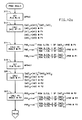
- the overall cycle of operation of manipulator 10 in the automatic mode is illustrated by the flow chart of Figure 5 a .
- the process begins by recalling point data, as illustrated by process step 250. Data for the next two programmed locations are recalled to provide time for preparation of circular motion data if circular motion is called for between these two recalled points.
- decision step 252 it is determined whether the circular motion type attribute has been programmed with the second of the recalled locations. If it has, the circular flag is set at process step 254. Also, two status markers are set to indicate the locations which correspond to the arc start point and arc end point. The latter being the third programmed location from the present location and the former being the programmed location immediately following the present location.
- the location data for the three arc reference points are loaded into dedicated storage locations for access by the math processor 63.
- process steps 254 and 256 would be skipped, In either event, the procedure continues at decision step 258 where it is determined whether a flag has been set indicating that circular motion is in effect.
- the next immediate move will not be the circular motion dictated by the detected circular motion attribute, however, the next immediate motion might in fact be the remainder of a previously begun circular move.
- the end location will be an arc intermediate point which is computed by math processor 63 and loaded into a dedicated memory location for access by cycle control 62.
- the arc intermediate point is read from the dedicated memory location.
- a data available flag set by math processor 63 is reset to indicate that the flag arc intermediate point has been read by cycle control 62. If the next move is not circular, process steps 260 and 262 are skipped.
- span interpolation data is initialised at process step 264. This includes the computation of the span length S p and the coordinate component ratios N cc .
- Cycle control 62 effects motion of the tool centrepoint 48 along a straight line between the present tool centerpoint location and the next span end point by interpolating intermediate points along the line at intervals determined by the servo interrupt signals.
- a span increment ⁇ S along the path is calculated as the product of the iteration time interval ⁇ t and the iteration velocity V k of the tool centerpoint.
- a transformation sub-routine is called to:
- step 272 If it is determined at decision step 272 that the distance remaining S RD is less than the span increment ⁇ S, execution proceeds through the on-page connector L-3.
- decision step 276 it is determined whether the circular move status has been set. If it has, it is determined at decision step 278 whether the current span end point corresponds to an arc end point by checking the status flags set during process step 254. If the span end point is not an arc end point, interpolation of intermediate points continues with deceleration through the on-page connector L-2. Motion on the circular arc through the arc intermediate points is continuous. Deceleration is only effected in approach to the arc end point and then only if motion is not programmed to continue therethrough into the next span. If the current span were not a circular arc, the circular move flag would not be sent and decsion step 278 would be skipped.
- a deceleration sub-routine is called to effect the reduction of velocity required prior to beginning the next span.
- deceleration interpolation of intermediate points is accomplished by the deceleration sub-routine to the end of span.
- a function associated with the end of span is executed at process step 282.
- the execution of the overall cycle control procedure concludes at decision step 292 where it is determined if the span end point is the last location of the programmed operation. If it is, the execution of the program is automatically repeated from a designated location by the recycle of terminal 294. If it is not, the next programmed locations are recalled at process step 250 through the on-page connector L-1.
- mathematic processor 63 defines intermediate points along the arc of Figure 4 b , and the cycle control 62 effects straight line motion between these points.
- the arc intermediate points are located according to a constant time interval resulting in physical spacing depending on the programmed velocity for the tool centerpoint.
- the arc intermediate points define end points for straight line motion effected in the automatic mode.
- point data for these end points is read from dedicated locations in the control common memory wherein the mathematic processor has stored the end point data as it is produced. This is contrasted to the data store locations in common memory used during the teaching operation.
- the data for the three arc reference points are loaded into memory locations for access by the mathematic processor 63.
- the path increment iteration procedure on the circular arc is then suspended until the mathematic processor 63 provides data for the first arc intermediate point through the assigned locations in the common memory.
- the first arc intermediate point data is normally calculated in advance of the tool centerpoint reaching the arc start point to prevent any delay.
- the data exchange between the math processor 63 and path control procedure is controlled by the use of flags indicating when data is available.
- Figure 5 b is a flow chart of procedures used to produce arc intermediate point data in response to the arc reference data. These procedures are executed periodically by the math processor 63 which operates asynchronously with the cycle control 62.
- the flow chart of Figure 5 b reflects two primary activates, i.e. the calculation of several variable values in preparation for the production of arc intermediate point data and the actual production of the arc intermediate point data.
- the circular motion type flag is tested. If it has been set true by process step 254 of the flow chart of Figure 5 a , the calculation of variable values for the next circular type motion will be effected by the process steps 422 through 448. If the circular motion type flag has not been set, the production of arc intermediate point data is carried out by the steps 450 through 470.
- execution continues at decision step 422 where it is determined whether or not the circular type flag has been set during the execution of a circular move. If the circular move flag has been set, the calculation of circular motion variable values proceeds at process step 436. If the circular motion type attribute is detected during the execution of a circular move, the variable values calculated in advance of the execution of that circular move are saved in secondary locations identified by the subscript 11. To indicate the presence of data in the secondary storage locations, a counter is set equal to 1 at process step 436. At process step 438, the centre of the arc is calculated. At process step 440, the partial arc angles U1 and U2 are calculated. At process steps 442, the tool vector orientation matrix (W3) is calculated.
- W3 tool vector orientation matrix
- process step 444 two plane orientation angles are calculated.
- process step 446 the process angle orientation matrix (W2) is calculated, and at process step 448, a variety of circular variables are initialised including the angular increment magnitude ⁇ ⁇ , the intermediate arc angle ⁇ ak , and the accumulated arc angle ⁇ ak .
- process step 424 the centre of the arc is calculated; at process step 426 the partial arc angles U1 and U2 are calculated; at process step 428 the tool orientation matrix (W3) is calculated; at process step 430, two plane orientation angles are calculated; at process step 432, the process angle matrix (W2) is calculated; and at process 434, circular motion variables are initialised.
- the circular flag is reset by process step 449 and execution of the procedure of the flow chart of Figure 5 b is terminated until the next periodic execution.
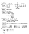
- the procedure for production of arc intermediate point data proceeds from decision step 420 with a determination that the circular motion type flag is not set.
- decision step 450 it is determined whether or not the circular move flag is set and if not, there is no need to produce any arc intermediate point data and the further execution of steps of the procedure is skipped by ending execution of the procedure.
- decision step 452 it is determined at decision step 452 whether arc intermediate point data previously produced is still available by detecting the state of the data available flag. If the data available flag is set, the cycle control 62 has not retrieved the last arc intermediate point data produced and further production of arc intermediate point data is not required. In that case, further execution of the procedure is skipped by ending execution.
- production of the arc intermediate point signals proceeds at process step 454 where the coordinates X ak , Y ak , and Z ak are calculated. Thereafter, at process step 456 the intermediate wrist orientation signals D ak , E ak , and R ak for the arc intermediate point are produced. At process step 458, these arc intermediate point coordinates and wrist orientation angles are loaded into the dedicated storage locations for access by the cycle control 62. At process step 460, the data available flag is set. At decision step 462, it is determined whether the arc intermediate point produced by execution of the steps 454 through 460 corresponds to the last arc point by comparing the value of the accumulated arc angle ⁇ ak to the magnitude of the arc angle ⁇ .
- the last arc intermediate point produced is the last arc intermediate point of the current circular move execution continues at decision step 466. There, it is determined whether or not the counter indicating the use of the secondary variable value storage is equal to zero. If it is not, the variable values are moved from the secondary storage to the primary storage at process step 468. At process step 470, the counter is set equal to O. Had it been determined at decision step 466 that the counter was already O, process steps 468 and 470 would be skipped.
- the intermediate arc angle ⁇ ak is decremented and the accumulated arc angle ⁇ ak is incremented at process 464 by the arc angle increment ⁇ ⁇ .
- the intermediate arc angle ⁇ ak is compared to zero. If the magnitude of the intermediate arc angle is less than or equal to zero, it is set equal to the difference between the included arc angle ⁇ and the accumulated arc angle ⁇ ak at process step 474. If the intermediate arc angle ⁇ ak is greater than zero, process step 474 is skipped.
- chords are defined, one connecting points P1 (406) and P2 (408), and the other connecting points P2 (408) and P3 (410). These chords constitute vectors defined by their coordinate components.
- perpendiculars of these chords are constructed by computing vector cross products V4 and V5 to determine the coordinate components of perpendiculars to the chords. This process includes the intermediate calculation of a vector V3 normal to the plane of the arc.
- the perpendiculars are then translated mathematically to bisect the chords. The intersection of the two perpendicular bisectors identifies the arc centre P0 (414).
- the arc centre coordinates are calculated from solutions of parametric equations of these perpendicular bisectors.
- a tool vector orientation matrix corresponding to process steps 428 and 442 of Figure 5 b shall be described with reference to Figure 10.
- the tool orientation angles i.e., tool pitch TD, tool yaw TE and tool roll TR are calculated from the tool data L, A, B and L′, A′, B′.
- the tool orientation matrix (W3) is evaluated using the values of the pitch, yaw, and roll angles determined at process step 376.
- the tool orientation matrix defines a transformation from the reference frame at the tool centerpoint and including the tool vector to a reference frame parallel to the input coordinate reference frame and having its origin coincident with the origin of the tool vector reference frame.
- the computations are based upon the fact that the tool vector (determined by the wrist orientation and tool geometry) must be coincident with the line of approach (determined by the work plane orientation and the desired process angles).
- the only unknowns at each of the three programmed points are the process angles.
- Orientation matrices, all of the same form, provide a basis to calculate the unknown process angles.
- the work plane roll angle WPE is set equal to zero. This corresponds to the work plane roll angle at the arc starting location 406. This assumed value together with the previously calculated value of work plane pitch and yaw angles provides sufficient information to evaluate all of the terms of the three by three work plane orientation matrix (W1).
- the work plane orientation matrix (W1) defines a transformation from the reference frame of the work plane including a workplane normal to a reference frame parallel to the input coordinate reference frame and having its origin coincident with the work plane reference frame.
- a wrist orientation matrix (W0) of the same form is evaluated using the wrist orientation angles (D, E and R).
- a process angle orientation matrix (W2) is defined to have the same form as the matrices from which it is calculated.
- Each matrix (W0), (W1), (W2) and (W3) provides for transformation through the rotations relating two frames of reference.
- the rotations are commonly identified as pitch (PC), yaw (YA) and roll (RL) and each matrix has the following form:
- the terms of the process angle orientation matrix are computed as the product of the inverse of the work plane orientation matrix (W1) ⁇ 1, the wrist orientation matrix (W0) and the tool orientation matrix (W3).
- the process angles are computed at process step 314 using the arc cosine and arc tangent functions of terms computed for the process angle matrix (W2) at process step 312.
- the process angle pitch calculated as the arc cosine of the value of the process angle orientation matrix element at the third row of the first column (cosine pitch);
- the process angle yaw is calculated as the arc tangent in the ratio of the process angle orientation matrix elements at the second row of the first column and the first row of the first column and the process angle roll is calculated as the arc tangent of the ratio of the process angle orientation matrix elements at the third row of the second column and the third row of the third column
- the work plane roll angle is set equal to U1, the angle between the arc radii at the arc start point P1 (406) and arc mid point P2 (408).
- the process angle orientation matrix is computed using the work plane orientation matrix at the arc mid point P2 (408) wherein the roll angle has the value U1.
- the process angles are computed in the same manner as at process step 314.
- the work plane roll angle is set equal to the value of the angle between the radii at the arc start point P1 (406) and arc end point P3 (410).
- the process angles at the arc end point are computed following the same procedure used for the arc start point 406 and arc mid point 408.
- Circular motion values are initialised corresponding to the process steps 434 and 448 of Figure 5 b as illustrated in Figure 13 1 2 This involves the division of the arc into a number of small segments or arc angle increments.
- the size of each segment S D is computed as a product of a predetermined time interval for traversing the arc segment and the velocity V p of the desired movement.
- another criterion such as the length of one weave of a welding cycle may be utilised to define the segment length SD as shown at process step 334. Knowing the segment length, the size of an associated segment angle ⁇ ⁇ is calculated at process steps 336 and 338 by dividing the segment length SD by the arc radius R.
- the arc angles ⁇ ak and ⁇ ak are initialised at process step 340.
- the intermediate arc angle ⁇ ak is set equal to the difference between the arc angle U1 and the segment angle ⁇ ⁇ .
- the accumulated arc angle ⁇ ak is set equal to the segment angle ⁇ ⁇ .
- the computation of the coordinates for an arc intermediate point, corresponding to process step 454 of Figure 5 b proceeds as illustrated in Figures 14 a and 14 b .
- the rectangular coordinates are determined by solving three simultaneous non-linear functions following the Newton Raphson technique. Functions which have a value of zero for solutions of point on the arc are defined and evaluated using the coordinates of the preceding arc intermediate point.
- a first function F1 defining a point on a circle having a centre P0 (point 414) at Xo, Yo, Zo and radius RD is evaluated using the current point (X k-1 ) on the arc.
- the value of F1 is zero for all points on the arc.
- a second function F2 defining the equation of a plane containing the circle is evaluated using the current point (X k-1 ) on the arc. The value of F2 is zero for all points lying in the plane of the circle.
- a third function F3 defining the vector dot product of the radial vector to the arc intermediate point and alternatively the radius to the arc mid point P2 or the radius to the arc end point P3 is evaluated wherein the included angle is equal to the intermediate arc angle ⁇ ak .
- the value of F3 is zero for all points on the arc having radius RD and centre P0 (X0, Y0, Z0).
- the matrix of partial derivatives is evaluated using the current point X k -1) on the arc.
- the inverse of the matrix of the partial derivatives is defined to be adjoint of the matrix of partial derivatives divided by the determinant of the matrix of partial derivatives.
- the inverse matrix is not evaluted and the calculations proceed by computing the product of the adjoint of the matrix of the partial derivatives and the matrix of the functions at process step 370.
- the results are then divided by the determinant of the matrix of partial derivatives as shown in the last terms of the equations at process step 372.
- the Newton Raphson solution technique provides for the substituion of the computed coordinates in the functions to test the solution against a limit, and the recomputation of the coordinates to produce a result within the limit, applicants do not execute this iterative test and recomputation. Rather, the coordinates computed by the single execution of these steps are satisfactorily precise by virtue of the limited magnitude of the change of position along the arc dictated by the product of tool centerpoint velocity and the predetermined interval.
- the resulting coordinate values are the coordinates for the next arc intermediate point. Those coordinates are used for generation of the commands which will move the tool tip 48 to the next arc intermediate point. However, it will be appreciated that the wrist orientation angles for the next point are also required.
- the workplane roll angle is set equal to the current value of the arc angle ⁇ .
- the value of the work plane roll angle is used in the evaluation of terms of the work plane orientation matrix.
- the process orientation angles PA(1), PA(2) and PA(3) are computed by linear interpolation between the values calculated for the arc start point, arc mid point and arc end point.
- the wrist orientation matrix is computed as the product of the work plane orientation matrix for roll angle ⁇ , the process angle orientation matrix for the values of the interpolated process angles, and the inverse of the tool orientation matrix.
- the wrist orientation angles are computed from inverse trigonometric functions applied to the terms of the wrist orientation matrix.
Landscapes
- Engineering & Computer Science (AREA)
- Computing Systems (AREA)
- Theoretical Computer Science (AREA)
- Human Computer Interaction (AREA)
- Manufacturing & Machinery (AREA)
- Physics & Mathematics (AREA)
- General Physics & Mathematics (AREA)
- Automation & Control Theory (AREA)
- Numerical Control (AREA)
- Manipulator (AREA)
Claims (12)
- Verfahren zum Überwachen der Bewegung eines Funktionselementes (50), das von einem Manipulator (10) getragen ist und das einen zugeordneten Arbeitspunkt (48) hat, wobei die Bewegung durch einen zweidimensionalen Bogen beschrieben wird, der einen Weg definiert, welcher von dem Arbeitspunkt und mit einer Geschwindigkeit des Arbeitspunktes durchlaufen werden soll, wobei der Bogen durch Eingangssignale definiert wird, die Koordinaten von drei Referenzpositionen (406, 408, 410) auf dem Bogen, einschließlich der Endlagestellen des Bogens, dargestellt wird, wobei die Geschwindigkeit des Arbeitspunktes durch weitere Eingangssignale definiert wird, wobei der Manipulator bewegbare Teile (15, 18, 20) zum Bewirken der Bewegung des Funktionselementes und einen Servomechanismus-Schaltkreis (64) zum Überwachen der Bewegung der bewegbaren Teile umfaßt, wobei die Bewegung bewirkt wird durch:(i) periodisches Erzeugen von Signalen (454, 456) für Bogen-Zwischenpositionen, welche Koordinaten von Zwischenpositionen entlang des Bogens darstellen; und(ii) Erzeugen von Maschinenkoordinatensignalen zum Überwachen des Servomechanismus-Schaltkreises in Abhängigkeit von dem Bogen-Zwischenpositionssignal (456), wobei die Maschinenkoordinatensignale die Bewegung der bewegbaren Teile zwischen ihren Positionen an dem momentanen Ort des Arbeitspunktes und dem Ort des Arbeitspunktes, der durch die nächste Zwischenposition definiert ist, definieren, wobei das Verfahren dadurch gekennzeichnet ist, daß:(a) Arbeitsebenen-Richtungswinkel in Abhängigkeit von den Eingangssignalen berechnet werden, die die Bogen-Referenzposition (Fig. 11) darstellen, wobei die Arbeitsebenen-Richtungswinkel die Lage einer Ebene (400) definieren, in welcher der Bogen liegt;(b) die Bogen-Zwischenpositionssignale (454, 456) in Abhängigkeit von den Arbeitsebenen-Richtungswinkeln und den Eingangssignalen, die die Bogen-Referenzposition und die Geschwindigkeit des Arbeitspunktes (454) definieren, erzeugt werden, wobei die so erzeugten Bogen-Zwischenpositionssignale eine Zwischenposition auf dem Bogen darstellen, zu der der Arbeitspunkt in einer vorbestimmten Zeit bewegt werden soll;(c) Zwischenpositionssignale, die Orte entlang linearer Wege zwischen Bogen-Zwischenpositionen definieren, in Abhängigkeit von den Bogen-Zwischenpositionssignalen erzeugt werden, wobei die Maschinenkoordinatensignale in Abhängigkeit von den Zwischenpositionssignalen erzeugt werden.
- Verfahren nach Anspruch 1, bei dem der Schritt des Erzeugens von Bogen-Zwischenpositionssignalen weiter dadurch gekennzeichnet ist, daß:(a) eine Bogensegmentlänge, welche ein Bogensegment definiert, das in einem vorbestimmten Zeitintervall durchlaufen werden soll, bestimmt wird (332 oder 334);(b) ein Winkelinkrement gegenüber der Bogensegmentlänge berechnet wird (338); und(c) die Koordinaten einer Position auf dem Bogen, die von der vorliegenden Position des Arbeitspunktes um das Winkelinkrement entfernt liegt, berechnet werden (454, 464).
- Verfahren nach Anspruch 2, bei dem das Erzeugen von Zwischenpositionssignalen dadurch gekennzeichnet ist, daß:(a) Koordinaten eines Arbeitspunkt-Ortes auf einem linearen Weg zwischen zwei aufeinanderfolgenden Bogen-Zwischenpositionen in Abhängigkeit von einem Servo-Unterbrechungssignal berechnet werden (266, 268), welches ein Inkrementzeitintervall ( Δ t), das die Geschwindigkeit darstellende Eingangssignal und die Bogen-Zwischenpositionssignale definiert; und(b) die Arbeitspunkt-Ortskoordinaten in Maschinenkoordinaten transformiert werden (268).
- Verfahren nach Anspruch 2, bei dem das Funktionselement von einem Gelenk (32) des Manipulators getragen ist, das Funktionselement einen zugeordneten Werkzeugvektor (402) hat und die Bewegung weiterhin durch eine gewünschte Annäherungslinie des Werkzeugvektors definiert ist, wobei das Verfahren weiter dadurch gekennzeichnet ist, daß:(a) die Annäherungslinie durch Eingangssignale definiert ist, die die Richtung des Gelenkes an den Referenzpositionen darstellen;(b) Gelenkrichtungs-Zwischensignale in Abhängigkeit von den Eingangssignalen erzeugt werden (456), welche die Gelenkrichtung und den Werkzeugvektor (402) darstellen, wobei die Gelenkrichtungs-Zwischensignale die Lage des Funktionselementes an der Bogen-Zwischenposition definieren; und(c) die Zwischenpositionssignale in Abhängigkeit von den Gelenkrichtungs-Zwischensignalen und den Bogen-Zwischenpositionssignalen erzeugt werden (264, 266, 268), so daß, wenn sie dem Servomechanismus-Schaltkreis aufgegeben werden, der Arbeitspunkt zu der Boden-Zwischenposition bewegt wird und das Funktionselement zu der Lage, die von den Richtungs-Zwischensignalen definiert ist, bewegt wird.
- Verfahren nach Anspruch 5, bei dem der Schritt des Erzeugens von Gelenkrichtungs-Zwischensignalen weiterhin dadurch gekennzeichnet ist, daß:(a) Prozeßwinkel an den Bogen-Referenzpositionen berechnet werden (432, 446), wobei die Prozeßwinkel die Annäherungslinie des Werkzeugvektors (402) an den Bogen-Referenzpositionen definieren;(b) Prozeßwinkel an den Bogen-Zwischenpositionen in Abhängigkeit von dem Winkelinkrement und den Prozeßwinkeln an den Bogen-Referenzpositionen berechnet werden (354);(c) eine Arbeitsebenen-Richtungsmatrix in Abhängigkeit von den Arbeitsebenen-Richtungswinkeln berechnet wird (356), wobei die Arbeitsebenen-Richtungsmatrix eine Transformation von einem Bezugssystem auf dem Bogen, das eine Normale zur Arbeitsebene enthält, in ein Bezugssystem definiert, das einen übereinstimmenden Ursprung hat und parallel zu dem Koordinatensystem ist, auf das die Eingangssignale bezogen werden;(d) eine Prozeßwinkel-Richtungsmatrix in Abhängigkeit von den Prozeßwinkeln an der Bogen-Zwischenposition berechnet wird (356), wobei die Prozeßwinkel-Richtungsmatrix eine Transformation von einem Bezugssystem an dem Arbeitspunkt, welches die Annäherungslinie enthält, in ein Bezugssystem an dem Arbeitspunkt definiert, das parallel zu dem Koordinatensystem ist, auf das die Eingangssignale bezogen werden;(e) eine Arbeitsvektor-Richtungsmatrix in Abhängigkeit von den Eingangssignalen, die den Arbeitsvektor definieren, berechnet wird (356), wobei die Arbeitsvektor-Richtungsmatrix eine Transformation von einem Bezugssystem an dem Arbeitspunkt, welches den Arbeitspunkt enthält, in ein Bezugssystem an dem Arbeitspunkt definiert, das parallel zu dem Koordinatensystem ist, auf das die Eingangssignale bezogen werden;(f) eine Gelenkrichtungsmatrix in Abhängigkeit von der Arbeitsebenen-Richtungsmatrix, der Prozeßwinkel-Richtungsmatrix und der Werkzeugvektor-Richtungsmatrix berechnet wird (356); und(g) die Gelenk-Richtungswinkel in Abhängigkeit von der Gelenk-Richtungsmatrix berechnet werden (358).
- Vorrichtung zum Überwachen der Bewegung eines Funktionselementes (50), das auf einer Planscheibe (44) eines Gelenkes (32) eines Manipulators (10) angebracht ist und das einen Arbeitspunkt (48) und einer Werkzeugvektor (402) zugeordnet hat, wobei die Bewegung durch einen zweidimensionalen Bogen, der einer von dem Arbeitspunkt zu sich durch laufenden Weg definiert, über eine gewünschte Annäherungslinie des Werkzeugvektors und durch eine Geschwindigkeit des Arbeitspunktes beschrieben wird, wobei der Bogen durch Eingangssignale definiert wird, die Koordinaten von drei Referenzpositionen (406, 408, 410) auf dem Bogen, einschließlich der Bogen-Endposition, darstellen, wobei die Annäherungslinie durch weitere Eingangssignale definiert ist, wobei die Geschwindigkeit des Arbeitspunktes durch weitere Eingangssignale definiert ist, wobei der Manipulator bewegbare Teile (16, 18, 22, 31, 33, 44) zum Bewirken der Bewegung des Funktionselementes und einen Servomechanismus-Schaltkreis zum Überwachen der Bewegung der bewegbaren Teile umfaßt, wobei die Vorrichtung dadurch gekennzeichnet ist, daß:(a) Mittel (63, Fig. 11) zum Berechnen von Arbeitsebenen-Richtungswinkeln in Abhängigkeit von den Eingangsignalen, die die Bogen-Referenzpositionen (406 - 410) darstellen, vorgesehen sind, wobei die Arbeitsebenen-Richtungswinkel die Lage einer Ebene definieren, in der der Bogen liegt;(b) Mittel (63, 454) zum periodischen Erzeugen von Bogen-Zwischenpositionssignalen in Abhängigkeit von den Eingangssignalen, die die Bogen-Referenzposition, der Geschwindigkeit des Arbeitspunktes und den Arbeitsebenen-Richtungswinkeln definieren, vorgesehen sind, wobei die Bogen-Zwischenpositionssignale einen Ort auf dem Bogen darstellen, zu dem der Arbeitspunkt bewegt werden soll; und(c) Mittel (62, 264, 266, 268) zum Erzeugen von Maschinen-Koordinatensignalen in Abhängigkeit von den Bogen-Zwischenpositionssignalen vorgesehen sind, wobei die Maschinenkoordinatensignale die Bewegung der bewegbaren Teile der Maschine zwischen ihrer gegenwärtigen Position und den Positionen, die durch die Bogen-Zwischenpositionssignale definiert sind, definieren.
- Vorrichtung nach Anspruch 6, bei der die Mittel zum Erzeugen von Bogen-Zwischenpositionssignalen weiterhin dadurch gekennzeichnet sind, daß:(a) Mittel (63, 332 oder 334) zum Bestimmen einer Bogensegmentlänge, durch die der Mittelpunkt des Werkzeuges in einem vorbestimmten Zeiterintervall bewegt werden soll, vorgesehen sind;(b) Mittel (63, 338) zum Berechnen eines Winkelinkrementes gegenüber der Bogensegmentlänge vorgesehen sind; und(c) Mittel (63, 454, 464) zum Berechnen der Koordinaten einer Position auf dem Bogen, die von der gegenwärtigen Position des Arbeitspunktes um das Winkelinkrement entfernt liegt, vorgesehen sind.
- Vorrichtung nach Anspruch 7, bei der die Mittel zum Erzeugen von Maschinenkoordinatensignalen weiter dadurch gekennzeichnet ist, daß:(a) Mittel (102) zum Erzeugen eines Servo-Unterbrechungssignales, das ein Inkrement-Zeitintervall darstellt, vorgesehen sind;(b) Mittel (62, 264, 266, 268), ansprechend auf das Servo-Unterbrechungssignal und die Bogen-Zwischenpositionssignale, zum Berechnen von Koordinaten eines Arbeitspunkt-Ortes auf einem linearen Weg zwischen zwei aufeinanderfolgenden Bogen-Zwischenpositionen vorgesehen sind; und(c) Mittel (62, 268) zum Transformieren der Arbeitspunkt-Ortskoordinaten in Maschinenkoordinaten vorgesehen sind.
- Vorrichtung nach Anspruch 8, weiter dadurch gekennzeichnet, daß Mittel (63, 456) zum Erzeugen von Gelenkrichtungs-Zwischensignalen in Abhängigkeit von den Eingangssignalen, die die Annäherungslinie des Werkzeugvektors darstellen, vorgesehen sind, wobei die Gelenkrichtungs-Zwischensignale die Lage des Funktionselementes an den Bogen-Zwischenpositionen definiert.
- Vorrichtung nach Anspruch 9, bei der der die Eingangssignale, die die Annäherungslinie des Werkzeugvektors darstellen, Richtungswinkel des Gelenkes darstellen und die Vorrichtung zum Erzeugen von Gelenkrichtungs-Zwischensignalen weiter dadurch gekennzeichnet ist, daß Mittel (63, 432, 446) zum Erzeugen von Prozeßwinkelsignalen in Abhängigkeit von den Arbeitsebenen-Richtungswinkeln und den Eingangssignalen, die die Gelenkrichtungswinkel und den Werkzeugvektor darstellen, vorgesehen sind, wobei die Prozeßwinkelsignale Winkel der gewünschten Annäherungslinie des Werkzeugvektors an jeder Bogen-Referenzposition darstellen.
- Vorrichtung nach Anspruch 10, bei der die Vorrichtung zum Erzeugen von Prozeßwinkelsignalen weiter dadurch gekennzeichnet ist, daß:(a) Mittel (63, 312, 320, 328), ansprechend auf die Mittel zum Berechnen von Arbeitsebenen-Richtungswinkeln, zum Berechnen einer Arbeitsebenen-Richtungsmatrix, welche eine Transformation von einem Bezugssystem auf dem Bogen, welches eine Normale zur Arbeitsebene umfaßt, in einem Bezugssystem mit übereinstimmendem Ursprung, das parallel zu dem Koordinatensystem, auf das die Eingangssignale bezogen sind, ist, vorgesehen sind;(b) Mittel (63, 312, 320, 328), ansprechend auf die Eingangssignale, welche die Richtungswinkel des Gelenkes darstellen, zum Berechnen einer Gelenk-Richtungsmatrix vorgesehen sind, wobei die Gelenk-Richtungsmatrix eine Transformation von einem Bezugssystem am Arbeitspunkt mit einer Achse parallel zu einer Normalen zur Planscheibe in ein Bezugssystem vom Arbeitspunkt parallel zu dem Koordinatensystem, auf das die Eingangssignale bezogen sind, definiert;(c) Mittel (63, 428, 442), ansprechend auf die Eingangssignale, die den Werkzeugvektor definieren, zum Berechnen einer Werkzeugvektor-Richtungsmatrix vorgesehen sind, wobei die Werkzeugvektor-Richtungsmatrix eine Transformation von einem Bezugssystem an dem Arbeitspunkt, das den Werkzeugvektor enthält, in ein Bezugssystem an dem Arbeitspunkt, das parallel zu dem Koordinatensystem ist, auf das die Eingangssignale bezogen sind, definiert;(d) Mittel (63, 312, 320, 328), ansprechend auf die Arbeitsebenen-Richtungsmatrix, die Gelenk-Richtungsmatrix und die Werkzeugvektormatrix, zum Berechnen einer Prozeßwinkel-Richtungsmatrix vorgesehen sind; und(e) Mittel (63, 314, 322, 330), ansprechend auf die Prozeßwinkel-Richtungsmatrix, zum Berechnen des Prozeßwinkels vorgesehen sind.
- Vorrichtung nach Anspruch 11, bei der die Mittel zum Erzeugen von Gelenkrichtungs-Zwischensignalen weiter dadurch gekennzeichnet sind, daß:(a) Mittel (63, 354), ansprechend auf das Winkelinkrement, zum Berechnen von Prozeßwinkeln an der Bogen-Zwischenposition vorgesehen sind;(b) Mittel (63, 356), ansprechend auf die Arbeitsebenen-Richtungsmatrix, die Prozeßwinkel-Richtungsmatrix und die Werkzeugvektor-Richtungsmatrix, zum Berechnen einer Gelenk-Richtungsmatrix vorgesehen sind; und(c) Mittel (63, 358), ansprechend auf die Gelenk-Richtungsmatrix, zum Berechnen der Gelenk-Richtungswinkel vorgesehen sind.
Applications Claiming Priority (2)
| Application Number | Priority Date | Filing Date | Title |
|---|---|---|---|
| US07/074,815 US4835710A (en) | 1987-07-17 | 1987-07-17 | Method of moving and orienting a tool along a curved path |
| US74815 | 2002-02-13 |
Publications (2)
| Publication Number | Publication Date |
|---|---|
| EP0299403A1 EP0299403A1 (de) | 1989-01-18 |
| EP0299403B1 true EP0299403B1 (de) | 1991-10-30 |
Family
ID=22121848
Family Applications (1)
| Application Number | Title | Priority Date | Filing Date |
|---|---|---|---|
| EP88111040A Expired EP0299403B1 (de) | 1987-07-17 | 1988-07-11 | Verfahren und Gerät zum Bewegen eines Werkzeuges entlang einer gekrümmten Bahn |
Country Status (5)
| Country | Link |
|---|---|
| US (1) | US4835710A (de) |
| EP (1) | EP0299403B1 (de) |
| JP (1) | JPS6448109A (de) |
| CA (1) | CA1329425C (de) |
| DE (1) | DE3865907D1 (de) |
Families Citing this family (91)
| Publication number | Priority date | Publication date | Assignee | Title |
|---|---|---|---|---|
| JPS6435605A (en) * | 1987-07-30 | 1989-02-06 | Fanuc Ltd | Numerical controller |
| JPH08384B2 (ja) * | 1987-09-16 | 1996-01-10 | ファナック株式会社 | ツール先端点の自動設定方式 |
| US5251127A (en) * | 1988-02-01 | 1993-10-05 | Faro Medical Technologies Inc. | Computer-aided surgery apparatus |
| EP0326768A3 (de) * | 1988-02-01 | 1991-01-23 | Faro Medical Technologies Inc. | Computerunterstütze chirurgische Vorrichtung |
| US5062755A (en) * | 1988-02-23 | 1991-11-05 | Macmillan Bloedel Limited | Articulated arm control |
| JP3207409B2 (ja) * | 1988-03-10 | 2001-09-10 | ファナック株式会社 | ロボットのツール姿勢制御方法 |
| US5276777A (en) * | 1988-04-27 | 1994-01-04 | Fanuc Ltd. | Locus correcting method for industrial robots |
| JP2512099B2 (ja) * | 1988-08-24 | 1996-07-03 | 松下電器産業株式会社 | ロボットの動作教示方法および制御装置 |
| US4972347A (en) * | 1988-10-11 | 1990-11-20 | Cincinnati Milacron Inc. | Method and apparatus for determining the correct tool dimensions for a three dimensional tool mounted on a manipulator |
| JPH02161503A (ja) * | 1988-12-14 | 1990-06-21 | Mitsubishi Heavy Ind Ltd | ロボットにおける教示位置データの修正・再生方法 |
| US4977494A (en) * | 1989-02-17 | 1990-12-11 | Hughes Aircraft Company | High speed digital motion controller architecture |
| EP0384925B1 (de) * | 1989-02-28 | 1995-11-22 | Siemens Aktiengesellschaft | Steuerungsverfahren bei einer numerischen Werkzeugmaschine oder einem Roboter |
| EP0701187B1 (de) * | 1989-05-17 | 2000-08-09 | Fujitsu Limited | Profilsteuerungssystem für Roboter |
| US5053976A (en) * | 1989-05-22 | 1991-10-01 | Honda Giken Kogyo Kabushiki Kaisha | Method of teaching a robot |
| US5079491A (en) * | 1989-05-23 | 1992-01-07 | Honda Giken Kogyo Kabushiki Kaisha | Robot control system |
| GB2232504B (en) * | 1989-05-23 | 1993-09-29 | Honda Motor Co Ltd | Method of teaching a robot |
| JPH0324606A (ja) * | 1989-06-22 | 1991-02-01 | Yutaka Kanayama | 移動ロボットの経路指定方法 |
| JPH0769738B2 (ja) * | 1989-09-01 | 1995-07-31 | 株式会社不二越 | ロボットの制御方法及び装置 |
| US5243690A (en) * | 1989-11-14 | 1993-09-07 | General Electric Company | Robot targeting using transit time control |
| US5229698A (en) * | 1990-08-06 | 1993-07-20 | Cincinnati Milacron Inc. | Method and apparatus for sub-span interpolation |
| US5179514A (en) * | 1990-08-08 | 1993-01-12 | The Research Foundation Of State University Of New York | Method and apparatus for trajectory control of robot manipulators or the like |
| EP0931516B1 (de) * | 1990-10-19 | 2008-08-20 | St. Louis University | System zur Lokalisierung einer chirurgischen Sonde relativ zum Kopf |
| US6347240B1 (en) | 1990-10-19 | 2002-02-12 | St. Louis University | System and method for use in displaying images of a body part |
| US6167295A (en) * | 1991-01-28 | 2000-12-26 | Radionics, Inc. | Optical and computer graphic stereotactic localizer |
| US6006126A (en) * | 1991-01-28 | 1999-12-21 | Cosman; Eric R. | System and method for stereotactic registration of image scan data |
| US5662111A (en) | 1991-01-28 | 1997-09-02 | Cosman; Eric R. | Process of stereotactic optical navigation |
| US6405072B1 (en) | 1991-01-28 | 2002-06-11 | Sherwood Services Ag | Apparatus and method for determining a location of an anatomical target with reference to a medical apparatus |
| US6675040B1 (en) | 1991-01-28 | 2004-01-06 | Sherwood Services Ag | Optical object tracking system |
| US5396160A (en) * | 1991-03-11 | 1995-03-07 | General Motors Corporation | Method of real-time machine path planning from a math model |
| US5297238A (en) * | 1991-08-30 | 1994-03-22 | Cimetrix Incorporated | Robot end-effector terminal control frame (TCF) calibration method and device |
| US5430643A (en) * | 1992-03-11 | 1995-07-04 | The United States Of America As Represented By The Administrator Of The National Aeronautics And Space Administration | Configuration control of seven degree of freedom arms |
| US5546508A (en) * | 1992-04-03 | 1996-08-13 | The United States Of America As Represented By The Administrator Of The National Aeronautics And Space Administration | Controlling flexible robot arms using high speed dynamics process |
| US5377310A (en) * | 1992-04-03 | 1994-12-27 | The United States Of America As Represented By The Administrator Of The National Aeronautics And Space Administration | Controlling under-actuated robot arms using a high speed dynamics |
| US5603318A (en) * | 1992-04-21 | 1997-02-18 | University Of Utah Research Foundation | Apparatus and method for photogrammetric surgical localization |
| DE69314688T2 (de) * | 1992-04-23 | 1998-02-19 | Heidenhain Gmbh Dr Johannes | Numerische Steuerungseinrichtung und Verfahren zur Steuerung der Bewegung eines Werkzeuges |
| US5340962A (en) * | 1992-08-14 | 1994-08-23 | Lumonics Corporation | Automatic control of laser beam tool positioning |
| US5438522A (en) * | 1992-12-18 | 1995-08-01 | Cincinnati Milacron Inc. | Method and apparatus for sub-span interpolation |
| DE69433588T2 (de) * | 1993-04-26 | 2005-02-03 | St. Louis University | Anzeige der lage einer sonde |
| FR2706345B1 (fr) * | 1993-06-11 | 1995-09-22 | Bertin & Cie | Procédé et dispositif de repérage dans l'espace d'un objet mobile tel qu'un capteur ou un outil porté par un robot. |
| JP3665353B2 (ja) * | 1993-09-14 | 2005-06-29 | ファナック株式会社 | ロボットの教示位置データの3次元位置補正量取得方法及びロボットシステム |
| US6978166B2 (en) * | 1994-10-07 | 2005-12-20 | Saint Louis University | System for use in displaying images of a body part |
| ATE320226T1 (de) | 1994-10-07 | 2006-04-15 | Univ St Louis | Chirurgische navigationsanordnung einschliesslich referenz- und ortungssystemen |
| GB9517214D0 (en) * | 1995-08-23 | 1995-10-25 | Renishaw Plc | Calibration of an articulating probe head for a coordinating positioning machine |
| US6167145A (en) * | 1996-03-29 | 2000-12-26 | Surgical Navigation Technologies, Inc. | Bone navigation system |
| US6296613B1 (en) | 1997-08-22 | 2001-10-02 | Synthes (U.S.A.) | 3D ultrasound recording device |
| US5903125A (en) * | 1997-02-06 | 1999-05-11 | Speedline Technologies, Inc. | Positioning system |
| US5886494A (en) * | 1997-02-06 | 1999-03-23 | Camelot Systems, Inc. | Positioning system |
| JP3269003B2 (ja) * | 1997-05-12 | 2002-03-25 | 川崎重工業株式会社 | ロボット制御装置 |
| US6025686A (en) * | 1997-07-23 | 2000-02-15 | Harnischfeger Corporation | Method and system for controlling movement of a digging dipper |
| US6434507B1 (en) | 1997-09-05 | 2002-08-13 | Surgical Navigation Technologies, Inc. | Medical instrument and method for use with computer-assisted image guided surgery |
| US6206964B1 (en) | 1997-11-10 | 2001-03-27 | Speedline Technologies, Inc. | Multiple head dispensing system and method |
| US6007631A (en) * | 1997-11-10 | 1999-12-28 | Speedline Technologies, Inc. | Multiple head dispensing system and method |
| US6214117B1 (en) | 1998-03-02 | 2001-04-10 | Speedline Technologies, Inc. | Dispensing system and method |
| US6064168A (en) * | 1998-03-13 | 2000-05-16 | Fanuc Robotics North America, Inc. | Method of controlling robot movement |
| EP1089669B1 (de) | 1998-06-22 | 2008-03-19 | AO Technology AG | Fiducial matching mittels fiducial-schraube |
| US6242880B1 (en) | 1998-09-08 | 2001-06-05 | Cimplus, Inc. | Tolerance based motion control system |
| US5959425A (en) * | 1998-10-15 | 1999-09-28 | Fanuc Robotics North America, Inc. | Vision guided automatic robotic path teaching method |
| ES2260901T3 (es) | 1999-03-17 | 2006-11-01 | Synthes Ag Chur | Dispositivo de planificacion y guia in situ de un injerto de ligamentos. |
| EP1171780A1 (de) | 1999-04-20 | 2002-01-16 | Synthes Ag Chur | Vorrichtung zur perkutanen bestimmung von koordinaten auf der oberfläche eines menschliches oder tierischen organs |
| DK1175592T3 (da) * | 1999-05-03 | 2003-10-06 | Synthes Ag | Positionsregistreringsanordning med hjælpemidler til fastlæggelse af tyngdekraftvektorens retning |
| US6356807B1 (en) | 1999-08-13 | 2002-03-12 | Fanuc Robotics North America, Inc. | Method of determining contact positions, calibration parameters, and reference frames for robot assemblies |
| US7274463B2 (en) * | 2003-12-30 | 2007-09-25 | Sensory Analytics | Anodizing system with a coating thickness monitor and an anodized product |
| US6674533B2 (en) | 2000-12-21 | 2004-01-06 | Joseph K. Price | Anodizing system with a coating thickness monitor and an anodized product |
| US7365860B2 (en) * | 2000-12-21 | 2008-04-29 | Sensory Analytics | System capable of determining applied and anodized coating thickness of a coated-anodized product |
| US6688458B2 (en) * | 2001-10-09 | 2004-02-10 | Speedline Technologies, Inc. | System and method for controlling a conveyor system configuration to accommodate different size substrates |
| GB0207431D0 (en) * | 2002-03-28 | 2002-05-08 | Qinetiq Ltd | Signal analysis system |
| JP4922584B2 (ja) * | 2004-12-10 | 2012-04-25 | 株式会社安川電機 | ロボットシステム |
| JP4827407B2 (ja) * | 2004-12-20 | 2011-11-30 | ユニチカ株式会社 | ダイレクトラミネート適性に優れた有機溶剤系塗料 |
| SG160423A1 (en) * | 2005-03-23 | 2010-04-29 | Hurco Co Inc | Method of tolerance-based trajectory planning and control |
| US7097540B1 (en) | 2005-05-26 | 2006-08-29 | General Electric Company | Methods and apparatus for machining formed parts to obtain a desired profile |
| ES2665428T3 (es) * | 2006-03-07 | 2018-04-25 | Sensory Analytics | Aparato móvil capaz de medidas superficiales del espesor de un revestimiento |
| KR101220121B1 (ko) * | 2006-06-30 | 2013-01-11 | 스타 마이크로닉스 컴퍼니 리미티드 | 이동체의 이동 제어 장치, 이동체의 이동 제어 방법 및공작 기계의 이동 제어 장치 |
| US8725283B2 (en) * | 2006-08-04 | 2014-05-13 | Hurco Companies, Inc. | Generalized kinematics system |
| CN101501589B (zh) * | 2006-08-04 | 2011-11-23 | 赫克公司 | 用于工具使用管理的系统和方法 |
| US7933677B2 (en) * | 2006-08-04 | 2011-04-26 | Hurco Companies, Inc. | System and method for surface finish management |
| US8024068B2 (en) * | 2006-08-04 | 2011-09-20 | Hurco Companies, Inc. | Machine tool control system |
| JP2010521271A (ja) * | 2007-03-16 | 2010-06-24 | ナンヤン・テクノロジカル・ユニバーシティー | 肛門直腸を検査する方法および装置 |
| EP2014413A1 (de) * | 2007-07-12 | 2009-01-14 | Lufthansa Technik AG | Anordnung, Verfahren und Vorrichtung zur Instandhaltung von Gasturbinenschaufeln |
| JP5028219B2 (ja) * | 2007-10-30 | 2012-09-19 | オリンパスメディカルシステムズ株式会社 | マニピュレータ装置および医療機器システム |
| DE102008027485B4 (de) * | 2008-06-09 | 2010-02-11 | Gsi Helmholtzzentrum Für Schwerionenforschung Gmbh | Deposition einer Solldosisverteilung in einem zyklisch bewegten Zielgebiet |
| JP5282014B2 (ja) * | 2009-11-18 | 2013-09-04 | 本田技研工業株式会社 | 教示ライン補正装置、教示ライン補正方法、及びそのプログラム |
| KR101876380B1 (ko) * | 2011-07-06 | 2018-07-11 | 삼성전자주식회사 | 매니퓰레이터 및 그 경로 생성 방법 |
| US20130119032A1 (en) * | 2011-11-11 | 2013-05-16 | Lincoln Global, Inc. | System and method for welding materials of different conductivity |
| US9144860B2 (en) * | 2012-03-29 | 2015-09-29 | Fanuc Robotics America Corporation | Robotic weld gun orientation normalization |
| CN103192647A (zh) * | 2013-04-23 | 2013-07-10 | 青岛速霸数控设备有限公司 | 一种多轴雕刻机 |
| CN104252153A (zh) * | 2013-06-28 | 2014-12-31 | 鸿富锦精密工业(深圳)有限公司 | Cnc加工程序生成系统及方法 |
| US10105849B1 (en) * | 2015-07-14 | 2018-10-23 | Glen C Wernersbach | Manufacturing system having robotic apparatus |
| JP6496340B2 (ja) * | 2017-03-17 | 2019-04-03 | ファナック株式会社 | スキャナ制御装置、ロボット制御装置及びリモートレーザ溶接ロボットシステム |
| US11897141B2 (en) * | 2018-11-19 | 2024-02-13 | Palletec, Llc | Automated fastening system |
| US12036663B2 (en) * | 2019-03-25 | 2024-07-16 | Abb Schweiz Ag | Method and control arrangement for determining a relation between a robot coordinate system and a movable apparatus coordinate system |
| US20230226682A1 (en) * | 2022-01-18 | 2023-07-20 | James Walter Beard, III | Method for Teaching Torch Orientation for Robotic Welding |
Family Cites Families (12)
| Publication number | Priority date | Publication date | Assignee | Title |
|---|---|---|---|---|
| US3909600A (en) * | 1972-06-26 | 1975-09-30 | Cincinnati Milacron Inc | Method and apparatus for controlling an automation along a predetermined path |
| US3920972A (en) * | 1974-07-16 | 1975-11-18 | Cincinnati Milacron Inc | Method and apparatus for programming a computer operated robot arm |
| JPS584377A (ja) * | 1981-03-18 | 1983-01-11 | 株式会社安川電機 | 関節形産業用ロボツトの制御装置 |
| JPH065486B2 (ja) * | 1981-03-26 | 1994-01-19 | 株式会社安川電機 | ロボットの軌跡制御方法 |
| JPS5822410A (ja) * | 1981-07-31 | 1983-02-09 | Fanuc Ltd | 数値制御方式 |
| JPS58143981A (ja) * | 1982-02-19 | 1983-08-26 | 株式会社日立製作所 | 産業用ロボツトの制御方法 |
| US4506335A (en) * | 1982-06-10 | 1985-03-19 | Cincinnati Milacron Inc. | Manipulator with controlled path motion |
| JPS59194213A (ja) * | 1983-04-19 | 1984-11-05 | Amada Co Ltd | 板材折曲げ加工装置 |
| JPS59218513A (ja) * | 1983-05-26 | 1984-12-08 | Fanuc Ltd | 工業用ロボツトの円弧制御法 |
| US4621332A (en) * | 1983-06-20 | 1986-11-04 | Hitachi, Ltd. | Method and apparatus for controlling a robot utilizing force, position, velocity, spring constant, mass coefficient, and viscosity coefficient |
| US4598380A (en) * | 1984-08-13 | 1986-07-01 | Cincinnati Milacron Inc. | Method and apparatus for controlling manipulator and workpiece positioner |
| JPS61114317A (ja) * | 1984-11-08 | 1986-06-02 | Matsushita Electric Ind Co Ltd | 産業用ロボツトの教示方法 |
-
1987
- 1987-07-17 US US07/074,815 patent/US4835710A/en not_active Expired - Lifetime
-
1988
- 1988-07-11 EP EP88111040A patent/EP0299403B1/de not_active Expired
- 1988-07-11 DE DE8888111040T patent/DE3865907D1/de not_active Expired - Lifetime
- 1988-07-15 CA CA000572219A patent/CA1329425C/en not_active Expired - Lifetime
- 1988-07-18 JP JP63178925A patent/JPS6448109A/ja active Pending
Also Published As
| Publication number | Publication date |
|---|---|
| US4835710A (en) | 1989-05-30 |
| EP0299403A1 (de) | 1989-01-18 |
| JPS6448109A (en) | 1989-02-22 |
| CA1329425C (en) | 1994-05-10 |
| DE3865907D1 (de) | 1991-12-05 |
Similar Documents
| Publication | Publication Date | Title |
|---|---|---|
| EP0299403B1 (de) | Verfahren und Gerät zum Bewegen eines Werkzeuges entlang einer gekrümmten Bahn | |
| US4598380A (en) | Method and apparatus for controlling manipulator and workpiece positioner | |
| US4453221A (en) | Manipulator with adaptive velocity controlled path motion | |
| EP0158447B2 (de) | System zum Steuern eines Roboters in Zusammenhang mit einem Drehtisch | |
| CA1202101A (en) | Manipulator with controlled path motion | |
| US4623971A (en) | Machine control with motor velocity constraint | |
| US4635206A (en) | Method and apparatus for oscillating a tool carried by a manipulator | |
| US4794540A (en) | Iterative spline function controlled positioning mechanism | |
| US4166543A (en) | Method and means for controlling an industrial robot | |
| US4258425A (en) | Self-programmed mechanical working apparatus | |
| US4433382A (en) | Apparatus for automatically adjusting the programmed location of a robot arm | |
| US4642752A (en) | Programmable automatic manipulator system | |
| US4348731A (en) | Automatic working apparatus and method of controlling the same | |
| US4538233A (en) | Apparatus and method for oscillatory motion control | |
| EP0076498B1 (de) | Verfahren zur Kontrolle eines Lichtbogenschweissbrenners eines Schweissroboters | |
| JPS59218513A (ja) | 工業用ロボツトの円弧制御法 | |
| EP0290178A2 (de) | Automatische krummlinige Weginterpolation für Industrieroboter | |
| US4972347A (en) | Method and apparatus for determining the correct tool dimensions for a three dimensional tool mounted on a manipulator | |
| EP0470564B1 (de) | Verfahren und Einrichtung zur Steuerung der Bewegung eines Maschinenteiles | |
| US4683543A (en) | Time-based interpolation control of a robot | |
| US4665493A (en) | Machining apparatus | |
| US5463297A (en) | Circular tracking method for robot | |
| JPH0570162B2 (de) | ||
| JPS60230207A (ja) | 工業用ロボツトとポジシヨナの連動制御システム | |
| JP2500207B2 (ja) | ウィ―ビング動作を行うア―ク溶接ロボット |
Legal Events
| Date | Code | Title | Description |
|---|---|---|---|
| PUAI | Public reference made under article 153(3) epc to a published international application that has entered the european phase |
Free format text: ORIGINAL CODE: 0009012 |
|
| AK | Designated contracting states |
Kind code of ref document: A1 Designated state(s): DE FR GB SE |
|
| 17P | Request for examination filed |
Effective date: 19890427 |
|
| 17Q | First examination report despatched |
Effective date: 19900906 |
|
| GRAA | (expected) grant |
Free format text: ORIGINAL CODE: 0009210 |
|
| AK | Designated contracting states |
Kind code of ref document: B1 Designated state(s): DE FR GB SE |
|
| REF | Corresponds to: |
Ref document number: 3865907 Country of ref document: DE Date of ref document: 19911205 |
|
| ET | Fr: translation filed | ||
| PLBE | No opposition filed within time limit |
Free format text: ORIGINAL CODE: 0009261 |
|
| STAA | Information on the status of an ep patent application or granted ep patent |
Free format text: STATUS: NO OPPOSITION FILED WITHIN TIME LIMIT |
|
| 26N | No opposition filed | ||
| EAL | Se: european patent in force in sweden |
Ref document number: 88111040.7 |
|
| REG | Reference to a national code |
Ref country code: GB Ref legal event code: IF02 |
|
| PGFP | Annual fee paid to national office [announced via postgrant information from national office to epo] |
Ref country code: DE Payment date: 20070919 Year of fee payment: 20 |
|
| PGFP | Annual fee paid to national office [announced via postgrant information from national office to epo] |
Ref country code: GB Payment date: 20070710 Year of fee payment: 20 |
|
| PGFP | Annual fee paid to national office [announced via postgrant information from national office to epo] |
Ref country code: SE Payment date: 20070710 Year of fee payment: 20 |
|
| PGFP | Annual fee paid to national office [announced via postgrant information from national office to epo] |
Ref country code: FR Payment date: 20070720 Year of fee payment: 20 |
|
| REG | Reference to a national code |
Ref country code: GB Ref legal event code: PE20 Expiry date: 20080710 |
|
| EUG | Se: european patent has lapsed | ||
| PG25 | Lapsed in a contracting state [announced via postgrant information from national office to epo] |
Ref country code: GB Free format text: LAPSE BECAUSE OF EXPIRATION OF PROTECTION Effective date: 20080710 |