EP0298284B1 - Farbbandkassette für Schreib- oder ähnliche Büromaschinen - Google Patents
Farbbandkassette für Schreib- oder ähnliche Büromaschinen Download PDFInfo
- Publication number
- EP0298284B1 EP0298284B1 EP88109596A EP88109596A EP0298284B1 EP 0298284 B1 EP0298284 B1 EP 0298284B1 EP 88109596 A EP88109596 A EP 88109596A EP 88109596 A EP88109596 A EP 88109596A EP 0298284 B1 EP0298284 B1 EP 0298284B1
- Authority
- EP
- European Patent Office
- Prior art keywords
- cassette
- spool
- take
- ribbon
- cassette according
- Prior art date
- Legal status (The legal status is an assumption and is not a legal conclusion. Google has not performed a legal analysis and makes no representation as to the accuracy of the status listed.)
- Expired - Lifetime
Links
- 238000004804 winding Methods 0.000 claims description 2
- 230000000903 blocking effect Effects 0.000 claims 5
- 238000000034 method Methods 0.000 description 2
- OKTJSMMVPCPJKN-UHFFFAOYSA-N Carbon Chemical compound [C] OKTJSMMVPCPJKN-UHFFFAOYSA-N 0.000 description 1
- 229910052799 carbon Inorganic materials 0.000 description 1
Images
Classifications
-
- B—PERFORMING OPERATIONS; TRANSPORTING
- B41—PRINTING; LINING MACHINES; TYPEWRITERS; STAMPS
- B41J—TYPEWRITERS; SELECTIVE PRINTING MECHANISMS, i.e. MECHANISMS PRINTING OTHERWISE THAN FROM A FORME; CORRECTION OF TYPOGRAPHICAL ERRORS
- B41J33/00—Apparatus or arrangements for feeding ink ribbons or like character-size impression-transfer material
- B41J33/14—Ribbon-feed devices or mechanisms
- B41J33/40—Ribbon-feed devices or mechanisms with arrangements for reversing the feed direction
- B41J33/42—Ribbon-feed devices or mechanisms with arrangements for reversing the feed direction manually
-
- B—PERFORMING OPERATIONS; TRANSPORTING
- B41—PRINTING; LINING MACHINES; TYPEWRITERS; STAMPS
- B41J—TYPEWRITERS; SELECTIVE PRINTING MECHANISMS, i.e. MECHANISMS PRINTING OTHERWISE THAN FROM A FORME; CORRECTION OF TYPOGRAPHICAL ERRORS
- B41J32/00—Ink-ribbon cartridges
Definitions
- the invention relates to an ink ribbon cassette for typewriters or similar office machines of the type specified in the preamble of claim 1.
- Modern office machines are designed according to DE-A1-3625089 for receiving closed ribbon supply cassettes which contain a ribbon supply or supply spool and a ribbon take-up spool with a piece of ribbon which run outside the cassettes between the two spools, so that it runs from the ribbon guides of the office machines can be included.
- the ribbons in such cartridges are single pass ribbons and are also known under the name carbon ribbons. After the ribbon has run through, it is used up in such a way that a new cassette must be inserted. This replacement of ribbon cartridges may also be necessary shortly before a letter or other document is finished. If no new ribbon cassette is available in such a case, it may take a considerable time until the letter or document is finally completed.
- the invention is based on the object of creating an ink ribbon cassette with which it is still possible to generate characters with the ribbon already used up even after the ribbon has run through. This object is achieved by the invention characterized in claim 1.
- the ribbon cassette according to the invention enables the possibility of rewinding, so that in emergencies the completion of a document is also possible without exchanging the ribbon cassette.
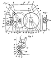
- FIG. 1 shows an ink ribbon cassette 1 for typewriters or similar office machines with a cassette housing 2, which consists of a pot-shaped base part 3 and a cover 4.
- a supply spool 5 is rotatably mounted on the bottom part 3, from which the ink ribbon is guided out of an outlet opening 8 of the housing 2 via deflection pins 6, 7, from there through the printing station and then again through an inlet opening 9 and deflection pins 10 , 11 arrives at a take-up spool 12.
- This take-up reel 12 has a take-up core 13 which is rotatably mounted on a bearing pin 14 of a pivoting lever 16 which can be pivoted about the bearing axis 15.
- a spring 17 articulated on the swivel lever 16 ensures that the ink ribbon 18 on the outer reel of the take-up spool 12 is always held in engagement with a toothed drive roller 19.
- This drive roller 19 is positively coupled when placed on a cassette holder 20 in the machine with a cutting-shaped transport device 21 arranged in this cassette holder 20.
- the bearing pin 14 slides in an elongated hole 23 of the housing 2, whose longitudinal edges 24, 25 to the pivot axis 15 of the pivot lever 16 are formed as radially shaped tracks.
- the take-up spool 12 can be locked in the locking position by means of a resilient locking lug 26 which interacts with the bearing pin 14 and which projects into the radially shaped path in the region at the end of the elongated hole 23.
- this elongated hole 23 is arranged in the cover 4 of the cassette housing 2, the latching lug 26 likewise being part of the cover 4 and having an undercut 27 for springing.
- the bearing pin 14 has an extension protruding from the cassette housing 2 for gripping by means of a finger or for receiving an actuating button for locking and unlocking the pivoting lever 16.
- the device for rewinding the supply reel 5 consists of a recess 28 in the hub 29, which is hexagonal for receiving a likewise hexagonal pencil or an Allen key.
- the pivot lever 16 is pivoted with the take-up spool 12 into the locking position, the locking pin 14 being locked behind the resilient locking lug 26. In this latching position, the take-up spool is no longer in engagement with the drive roller 19. Then the supply spool 5 is turned back in the direction of the arrow 30 by means of a pencil, an Allen key or another tool. After this turning back, the pivot lever 16 is unlocked again by hand, so that the outer winding of the take-up reel 12 rests resiliently on the drive roller 19. The writing process can then be continued again.
- the toothed disc coupled to the supply spool 5 must have a toothing which enables the supply spool 4 to be rotated in both directions of rotation.
- the resilient pawl 32 must also be designed accordingly.
- the supply reel 5 can also be rewound using a coin or a screwdriver if the recess has corresponding receiving slots 33, 34 according to FIG. 1.
- FIG. 3 shows a possibility of rewinding the ink ribbon, in which the drive roller can remain in engagement with the take-up spool 12.
- the backstop 35 must be unlocked for the drive roller 19 for rewinding the ribbon 18 from the take-up reel 12 to the supply reel 5.
- the drive roller 19 has a ratchet wheel 36, which can be locked against reverse rotation by a resilient pawl 37.
- the pawl 37 is adjustable in a locking position for disengagement with the ratchet wheel 36.
- the pawl 37 has a locking pin 38 which has a handle protruding from the housing 2 and is adjustable in a slot-like guide 39.
- a longitudinal edge 40 of this guide 39 has a resilient locking lug 41 which projects into the movement path of the locking pin 38.
- the pawl 37 when the ribbon has run through, the pawl 37 must be disengaged from the ratchet wheel 36 so that the supply spool can be rotated in the direction of arrow 30 by the means described above. This also enables the operator to end the writing process without exchanging the ink ribbon cassette.
Landscapes
- Impression-Transfer Materials And Handling Thereof (AREA)
Description
- Die Erfindung betrifft eine Farbbandkassette für Schreib- oder ähnliche Büromaschinen der im Oberbegriff des Patentanspruchs 1 angegebenen Art.
- Moderne Büromaschinen sind gemäß DE-A1-3625089 zur Aufnahme von verschlossenen Farbbandvorratskassetten konstruiert, welche eine Farbbandvorrats- oder -zuführspule und eine Farbbandaufnahmespule mit einem Stück Farbband enthalten, die außerhalb der Kassetten zwischen den beiden Spulen verlaufen, so daß es von den Farbbandführungen der Büromaschinen aufgenommen werden kann. Die Farbbänder in derartigen Kassetten sind Einzeldurchlauffarbbänder und sind auch unter dem Namen Karbonbänder bekannt. Nach Durchlauf des Farbbandes ist dieses derart verbraucht, daß eine neue Kassette eingesetzt werden muß. Dieses Auswechseln von Farbbandkassetten kann auch kurz vor Beendigung eines Briefes oder eines sonstigen Schriftstückes erforderlich sein. Wenn in einem solchen Fall keine neue Farbbandkassette vorrätig ist, kann eine beträchtliche Zeit bis zur endgültigen Fertigstellung des Briefes bzw. des Schriftstückes vergehen.
- Der Erfindung liegt nun die Aufgabe zugrunde, eine Farbbandkassette zu schaffen, mit der auch nach Durchlauf des Farbbandes noch die Erzeugung von Schriftzeichen mit dem ansich bereits verbrauchten Band möglich ist. Diese Aufgabe wird durch die im Patentanspruch 1 gekennzeichnete Erfindung gelöst.
- Die erfindungsgemäße Farbbandkassette ermöglicht eine Rückspulmöglichkeit, wodurch in Notfällen die Fertigstellung eines Schriftstückes auch ohne Austausch der Farbbandkassette möglich ist.
- Weitere vorteilhafte Ausgestaltungen des Erfindungsgegenstandes sind den weiteren Unteransprüchen zu entnehmen. Die Erfindung wird anhand von Ausführungsbeispielen im folgenden näher beschrieben.
- Es zeigen:
- Figur 1
- eine Draufsicht auf die Farbbandkassette,
- Figur 2
- eine Einzelheit aus Figur 1 in Seitenansicht und
- Figur 3
- die Antriebswalze mit der Rücklaufsperre.
- Die Figur 1 zeigt eine Farbbandkassette 1 für Schreib- oder ähnliche Büromaschinen mit einem Kassettengehäuse 2, das aus einem topfförmigen Bodenteil 3 und einem Deckel 4 besteht. In dem Kassettengehäuse 2 ist auf derem Bodenteil 3 eine Vorratsspule 5 drehbar gelagert, von der das Farbband über Umlenkstifte 6, 7 aus einer Austrittsöffnung 8 des Gehäuses 2 herausgeführt wird, von da durch die Druckstation gelangt und dann wieder durch eine Eintrittsöffnung 9 und Umlenkstifte 10, 11 zu einer Aufwickelspule 12 gelangt. Diese Aufwickelspule 12 weist einen Aufwickelkern 13 auf, der auf einem Lagerzapfen 14 eines um die Lagerachse 15 schwenkbaren Schwenkhebels 16 drehbar gelagert ist. Eine an dem Schwenkhebel 16 angelenkte Feder 17 sorgt dafür, daß das Farbband 18 auf dem äußeren Wickel der Aufwickelspule 12 stets mit einer verzahnten Antriebswalze 19 in Eingriff gehalten wird. Diese Antriebswalze 19 wird beim Aufsetzen auf eine Kassettenaufnahme 20 in der Maschine mit einer in dieser Kassettenaufnahme 20 angeordneten schneidenförmig ausgebildeten Transportvorrichtung 21 formschlüssig gekuppelt. Beim Durchlauf des Farbbandes 18 durch die Druckstation in Pfeilrichtung 22 mittels der Antriebswalze 19 nimmt der Durchmesser der Aufwickelspule 12 ständig zu. Hierbei gleitet der Lagerzapfen 14 in einem Langloch 23 des Gehäuses 2, dessen Längskanten 24, 25 zu der Schwenkachse 15 des Schwenkhebels 16 als radial geformte Bahnen ausgebildet sind. Die Aufwickelspule 12 ist mittels einer mit dem Lagerzapfen 14 zusammenwirkenden federnden Rastnase 26 in der Raststellung verrastbar, der im Bereich am Ende des Langloches 23 in die radial geformte Bahn hineinragt. Dieses Langloch 23 ist übrigens in dem Deckel 4 des Kassettengehäuses 2 angeordnet, wobei die Rastnase 26 ebenfalls Bestandteil des Deckels 4 ist und zum Federn eine Hinterschneidung 27 aufweist. Der Lagerzapfen 14 weist eine aus dem Kassettengehäuse 2 herausragende Verlängerung zum Anfassen mittels Finger oder zur Aufnahme eines Betätigungsknopfes zum Ver- und Entrasten des Schwenkhebels 16 auf.
- Die Vorrichtung zum Rückspulen der Vorratsspule 5 besteht aus einer Ausnehmung 28 in der Nabe 29, die sechseckig zur Aufnahme eines ebenfalls sechseckigen Bleistiftes oder eines Imbusschlüssels ausgebildet ist. Zum Rückspulen des Farbbandes 18 wird der Schwenkhebel 16 mit der Aufwickelspule 12 in die Raststellung verschwenkt, wobei der Rastzapfen 14 hinter der federnden Rastnase 26 verrastet. In dieser Raststellung ist die Aufwickelspule nicht mehr in Eingriff mit der Antriebswalze 19. Dann wird die Vorratsspule 5 in Pfeilrichtung 30 mittels eines Bleistiftes, Imbusschlüssels oder eines sonstigen Hilfsmittels zurückgedreht. Nach diesem Zurückdrehen wird der Schwenkhebel 16 wieder von Hand entrastet, so daß der äußere Wickel der Aufwickelspule 12 wieder federnd an der Antriebswalze 19 anliegt. Damit kann der Schreibvorgang wieder fortgesetzt werden. Der Austausch einer neuen Kassette kann somit zu einem späteren Zeitpunkt erfolgen. Die mit der Vorratsspule 5 gekoppelte Zahnscheibe muß eine Verzahnung aufweisen, die ein Drehen der Vorratsspule 4 in beiden Drehrichtungen ermöglicht. Zu diesem Zweck muß auch die federnde Klinke 32 entsprechend ausgebildet sein.
- Das Rückspulen der Vorratssspule 5 kann auch über ein Geldstück oder einen Schraubendreher erfolgen, wenn die Ausnehmung entsprechende Aufnahmeschitze 33, 34 gemäß Figur 1 aufweist.
- In der Figur 3 ist eine Möglichkeit des Rückspulens des Farbbandes dargestellt, bei dem die Antriebswalze mit der Aufwickelspule 12 in Eingriff bleiben kann. Hierbei muß die Rücklaufsperre 35 für die Antriebswalze 19 zum Rückspulen des Farbbandes 18 von der Aufwickelspule 12 auf die Vorratsspule 5 entsperrt werden. Hierbei weist die Antriebswalze 19 ein Sperrad 36 auf, das durch eine federnde Sperrklinke 37 gegen Rückdrehung sperrbar ist. Die Sperrklinke 37 ist in eine Raststellung zum Außereingriffbringen mit dem Sperrad 36 verstellbar. Die Sperrklinke 37 weist einen Rastzapfen 38 auf, der einen aus dem Gehäuse 2 herausragenden Handgriff hat und in einer langlochartigen Führung 39 verstellbar ist. Eine Längskante 40 dieser Führung 39 weist eine in die Bewegungsbahn des Rastzapfens 38 hineinragende, federnde Rastnase 41 auf. Wenn das Farbband durchgelaufen ist muß in diesem Fall die Sperrklinke 37 außer Eingriff mit dem Sperrad 36 gebracht werden, so daß die Vorratsspule mit den oben beschriebenen Mitteln in Pfeilrichtung 30 gedreht werden kann. Auch hierdurch ist es der Bedienungsperson möglich, den Schreibvorgang ohne eines Austausches der Farbbandkassette zu beenden.
Claims (9)
Applications Claiming Priority (2)
| Application Number | Priority Date | Filing Date | Title |
|---|---|---|---|
| DE3722226 | 1987-07-04 | ||
| DE19873722226 DE3722226A1 (de) | 1987-07-04 | 1987-07-04 | Farbbandkassette fuer schreib- oder aehnliche bueromaschinen |
Publications (2)
| Publication Number | Publication Date |
|---|---|
| EP0298284A1 EP0298284A1 (de) | 1989-01-11 |
| EP0298284B1 true EP0298284B1 (de) | 1991-08-07 |
Family
ID=6330962
Family Applications (1)
| Application Number | Title | Priority Date | Filing Date |
|---|---|---|---|
| EP88109596A Expired - Lifetime EP0298284B1 (de) | 1987-07-04 | 1988-06-16 | Farbbandkassette für Schreib- oder ähnliche Büromaschinen |
Country Status (3)
| Country | Link |
|---|---|
| US (1) | US4990007A (de) |
| EP (1) | EP0298284B1 (de) |
| DE (2) | DE3722226A1 (de) |
Families Citing this family (11)
| Publication number | Priority date | Publication date | Assignee | Title |
|---|---|---|---|---|
| US5318368A (en) * | 1992-09-24 | 1994-06-07 | Pitney Bowes Inc. | Thermal transfer ribbon having ribbon follower |
| US5267801A (en) * | 1992-12-30 | 1993-12-07 | Dennis Huang | Ribbon inker |
| WO1994022673A1 (en) * | 1993-04-06 | 1994-10-13 | Ayres David W | Disposable ribbon cassette within a reloadable cartridge |
| JPH11348395A (ja) * | 1998-06-04 | 1999-12-21 | Fuji Photo Film Co Ltd | プリンタのインクリボンゴミ付着防止方法およびそのプリンタ |
| USD458295S1 (en) | 2000-07-27 | 2002-06-04 | Iimak | Printer cassette |
| USD453179S1 (en) | 2000-07-27 | 2002-01-29 | Iimak | Printer cassette |
| US6910819B2 (en) * | 2003-08-12 | 2005-06-28 | Brady Worldwide, Inc. | Printer cartridge |
| USD527761S1 (en) | 2005-02-17 | 2006-09-05 | International Imaging Materials, Inc. | Printer cassette |
| US8324413B2 (en) * | 2008-12-23 | 2012-12-04 | Texaco Inc. | Low melting point triglycerides for use in fuels |
| US8361172B2 (en) * | 2008-12-23 | 2013-01-29 | Chevron U.S.A. Inc. | Low melting point triglycerides for use in fuels |
| GB202216618D0 (en) * | 2022-11-08 | 2022-12-21 | Dover Europe Sarl | Tape Transfer Apparatus and Method of Operation |
Family Cites Families (6)
| Publication number | Priority date | Publication date | Assignee | Title |
|---|---|---|---|---|
| US3731781A (en) * | 1968-07-16 | 1973-05-08 | Ibm | Ribbon supply cartridge |
| US3665855A (en) * | 1970-04-24 | 1972-05-30 | Scm Corp | Spring-returned power driven ribbon |
| DE3164817D1 (en) * | 1980-03-13 | 1984-08-23 | Nec Corp | A cartridge for an inked ribbon for an impact printer |
| US4337001A (en) * | 1980-07-28 | 1982-06-29 | Scm Corporation | Releasable ribbon locking device in a ribbon cartridge |
| JPS6137462A (ja) * | 1984-07-31 | 1986-02-22 | Silver Seiko Ltd | 印字リボンカセツト |
| DE3625089A1 (de) * | 1985-08-07 | 1987-02-19 | Olympia Ag | Farbbandkassette fuer schreib- oder bueromaschinen aehnlicher bauart |
-
1987
- 1987-07-04 DE DE19873722226 patent/DE3722226A1/de not_active Withdrawn
-
1988
- 1988-06-16 EP EP88109596A patent/EP0298284B1/de not_active Expired - Lifetime
- 1988-06-16 DE DE8888109596T patent/DE3864094D1/de not_active Expired - Fee Related
- 1988-07-01 US US07/213,963 patent/US4990007A/en not_active Expired - Fee Related
Also Published As
| Publication number | Publication date |
|---|---|
| DE3722226A1 (de) | 1989-01-12 |
| DE3864094D1 (de) | 1991-09-12 |
| EP0298284A1 (de) | 1989-01-11 |
| US4990007A (en) | 1991-02-05 |
Similar Documents
| Publication | Publication Date | Title |
|---|---|---|
| EP0143250B1 (de) | Tintenschreibvorrichtung mit einem auswechselbaren Schreibkopf | |
| DE3003886C2 (de) | ||
| EP0298284A1 (de) | Farbbandkassette für Schreib- oder ähnliche Büromaschinen | |
| DE2951610C2 (de) | Farbbandkassette für eine Schreib- o.ä. Büromaschine | |
| DE3406616C2 (de) | ||
| DE68928418T2 (de) | Verriegelungsvorrichtung für abnehmbare Frankiermaschine | |
| DE3106958A1 (de) | Auf eine schreib- oder aehnliche bueromaschine aufsetzbare farbbandkassette | |
| DE2921799A1 (de) | Vorschubvorrichtung fuer das aufzeichnungsmaterial eines druckers | |
| EP0264595A2 (de) | Aufzeichnungsvorrichtung für Schreib- oder Büromaschinen ähnlicher Bauart | |
| DE2547957C3 (de) | Löschvorrichtung für kraftangetriebene Schreib- o.a. Büromaschinen | |
| EP0249159B1 (de) | Farbbandkassette für Schreib-oder Büromaschinen ähnlicher Bauart | |
| DE3540925C2 (de) | ||
| DE3211402C2 (de) | ||
| DE2931326A1 (de) | Schreib- o.ae. bueromaschine mit einer farb- und einer korrektureinrichtung | |
| DE3920373A1 (de) | Schreib- oder buermomaschine aehnlicher bauart zum erzeugen von volldruckzeichen und/oder farbbildern von grafischen darstellungen oder mustern | |
| DE3625089C2 (de) | ||
| DE3314867C2 (de) | ||
| DE2253673C3 (de) | Vorrichtung zur Aufnahme einer eine Vorratsspule lagernden Vorratskassette oder einer kassettenlosen Vorratsspule für Farbbänder in Schreib- oder ähnlichen Maschinen | |
| DE2455971C3 (de) | Aufwickelspule für einmalig verwendbare Farbbänder in kraftangetriebenen Schreib- und ähnlichen Büromaschinen | |
| DE3919119A1 (de) | Farbbandkassette mit auswechselbaren farbbandspulen fuer schreib- oder bueromaschinen aehnlicher bauart | |
| DE3938212A1 (de) | Schreib- oder aehnliche bueromaschine mit einer aufnahmevorrichtung fuer eine farbbandkassette | |
| DE3109926A1 (de) | Auf eine schreib- oder aehnliche bueromaschine aufsetzbare bandkassette mit einem farb- oder korrekturband | |
| DE2253673A1 (de) | Farbbandeinrichtung mit einem behaelter zur aufnahme einer vorratsspule in einer bueromaschine | |
| DE2261412B1 (de) | Vorrichtung zum OEffnen und Schliessen der Fuehrungsschlitze einer Farbbandgabel an Schreib- oder aehnlichen Bueromaschinen | |
| DE3524059A1 (de) | Farbbandkassette fuer eine schreib- oder bueromaschine aehnlicher bauart |
Legal Events
| Date | Code | Title | Description |
|---|---|---|---|
| PUAI | Public reference made under article 153(3) epc to a published international application that has entered the european phase |
Free format text: ORIGINAL CODE: 0009012 |
|
| AK | Designated contracting states |
Kind code of ref document: A1 Designated state(s): CH DE FR GB IT LI NL |
|
| 17P | Request for examination filed |
Effective date: 19890331 |
|
| RAP1 | Party data changed (applicant data changed or rights of an application transferred) |
Owner name: AEG OLYMPIA OFFICE GMBH |
|
| 17Q | First examination report despatched |
Effective date: 19900713 |
|
| GRAA | (expected) grant |
Free format text: ORIGINAL CODE: 0009210 |
|
| AK | Designated contracting states |
Kind code of ref document: B1 Designated state(s): CH DE FR GB IT LI NL |
|
| ET | Fr: translation filed | ||
| GBT | Gb: translation of ep patent filed (gb section 77(6)(a)/1977) | ||
| REF | Corresponds to: |
Ref document number: 3864094 Country of ref document: DE Date of ref document: 19910912 |
|
| ITF | It: translation for a ep patent filed | ||
| PGFP | Annual fee paid to national office [announced via postgrant information from national office to epo] |
Ref country code: GB Payment date: 19920508 Year of fee payment: 5 |
|
| PGFP | Annual fee paid to national office [announced via postgrant information from national office to epo] |
Ref country code: FR Payment date: 19920515 Year of fee payment: 5 |
|
| PLBE | No opposition filed within time limit |
Free format text: ORIGINAL CODE: 0009261 |
|
| STAA | Information on the status of an ep patent application or granted ep patent |
Free format text: STATUS: NO OPPOSITION FILED WITHIN TIME LIMIT |
|
| PGFP | Annual fee paid to national office [announced via postgrant information from national office to epo] |
Ref country code: DE Payment date: 19920615 Year of fee payment: 5 |
|
| PGFP | Annual fee paid to national office [announced via postgrant information from national office to epo] |
Ref country code: NL Payment date: 19920630 Year of fee payment: 5 |
|
| 26N | No opposition filed | ||
| PGFP | Annual fee paid to national office [announced via postgrant information from national office to epo] |
Ref country code: CH Payment date: 19920928 Year of fee payment: 5 |
|
| PG25 | Lapsed in a contracting state [announced via postgrant information from national office to epo] |
Ref country code: GB Effective date: 19930616 |
|
| PG25 | Lapsed in a contracting state [announced via postgrant information from national office to epo] |
Ref country code: LI Effective date: 19930630 Ref country code: CH Effective date: 19930630 |
|
| PG25 | Lapsed in a contracting state [announced via postgrant information from national office to epo] |
Ref country code: NL Effective date: 19940101 |
|
| GBPC | Gb: european patent ceased through non-payment of renewal fee |
Effective date: 19930616 |
|
| NLV4 | Nl: lapsed or anulled due to non-payment of the annual fee | ||
| PG25 | Lapsed in a contracting state [announced via postgrant information from national office to epo] |
Ref country code: FR Effective date: 19940228 |
|
| REG | Reference to a national code |
Ref country code: CH Ref legal event code: PL |
|
| PG25 | Lapsed in a contracting state [announced via postgrant information from national office to epo] |
Ref country code: DE Effective date: 19940301 |
|
| REG | Reference to a national code |
Ref country code: FR Ref legal event code: ST |
|
| PG25 | Lapsed in a contracting state [announced via postgrant information from national office to epo] |
Ref country code: IT Free format text: LAPSE BECAUSE OF NON-PAYMENT OF DUE FEES Effective date: 20050616 |