EP0297430A2 - Traction or load carrying vehicle provided with a free-space between the rear wheels - Google Patents
Traction or load carrying vehicle provided with a free-space between the rear wheels Download PDFInfo
- Publication number
- EP0297430A2 EP0297430A2 EP88110001A EP88110001A EP0297430A2 EP 0297430 A2 EP0297430 A2 EP 0297430A2 EP 88110001 A EP88110001 A EP 88110001A EP 88110001 A EP88110001 A EP 88110001A EP 0297430 A2 EP0297430 A2 EP 0297430A2
- Authority
- EP
- European Patent Office
- Prior art keywords
- tractor
- truck according
- rear wheels
- vehicle
- drive
- Prior art date
- Legal status (The legal status is an assumption and is not a legal conclusion. Google has not performed a legal analysis and makes no representation as to the accuracy of the status listed.)
- Granted
Links
- 230000008878 coupling Effects 0.000 claims abstract description 9
- 238000010168 coupling process Methods 0.000 claims abstract description 9
- 238000005859 coupling reaction Methods 0.000 claims abstract description 9
- 238000010276 construction Methods 0.000 claims description 25
- 230000009467 reduction Effects 0.000 claims description 7
- 230000001771 impaired effect Effects 0.000 claims description 4
- 239000002689 soil Substances 0.000 description 9
- 239000000725 suspension Substances 0.000 description 7
- 230000005540 biological transmission Effects 0.000 description 5
- 230000000694 effects Effects 0.000 description 4
- 230000005484 gravity Effects 0.000 description 4
- 230000008901 benefit Effects 0.000 description 3
- 239000003337 fertilizer Substances 0.000 description 3
- XLYOFNOQVPJJNP-UHFFFAOYSA-N water Substances O XLYOFNOQVPJJNP-UHFFFAOYSA-N 0.000 description 3
- 241000894006 Bacteria Species 0.000 description 1
- 230000001154 acute effect Effects 0.000 description 1
- QVGXLLKOCUKJST-UHFFFAOYSA-N atomic oxygen Chemical compound [O] QVGXLLKOCUKJST-UHFFFAOYSA-N 0.000 description 1
- 238000009412 basement excavation Methods 0.000 description 1
- 230000008859 change Effects 0.000 description 1
- 230000007613 environmental effect Effects 0.000 description 1
- 230000002349 favourable effect Effects 0.000 description 1
- 230000004720 fertilization Effects 0.000 description 1
- 238000003306 harvesting Methods 0.000 description 1
- 230000002706 hydrostatic effect Effects 0.000 description 1
- 238000009434 installation Methods 0.000 description 1
- 239000007788 liquid Substances 0.000 description 1
- 239000000463 material Substances 0.000 description 1
- 229910052760 oxygen Inorganic materials 0.000 description 1
- 239000001301 oxygen Substances 0.000 description 1
- 239000000575 pesticide Substances 0.000 description 1
- 230000008635 plant growth Effects 0.000 description 1
- 230000000717 retained effect Effects 0.000 description 1
- 239000007921 spray Substances 0.000 description 1
Images

Classifications
-
- B—PERFORMING OPERATIONS; TRANSPORTING
- B60—VEHICLES IN GENERAL
- B60K—ARRANGEMENT OR MOUNTING OF PROPULSION UNITS OR OF TRANSMISSIONS IN VEHICLES; ARRANGEMENT OR MOUNTING OF PLURAL DIVERSE PRIME-MOVERS IN VEHICLES; AUXILIARY DRIVES FOR VEHICLES; INSTRUMENTATION OR DASHBOARDS FOR VEHICLES; ARRANGEMENTS IN CONNECTION WITH COOLING, AIR INTAKE, GAS EXHAUST OR FUEL SUPPLY OF PROPULSION UNITS IN VEHICLES
- B60K17/00—Arrangement or mounting of transmissions in vehicles
- B60K17/04—Arrangement or mounting of transmissions in vehicles characterised by arrangement, location, or kind of gearing
- B60K17/043—Transmission unit disposed in on near the vehicle wheel, or between the differential gear unit and the wheel
-
- B—PERFORMING OPERATIONS; TRANSPORTING
- B62—LAND VEHICLES FOR TRAVELLING OTHERWISE THAN ON RAILS
- B62D—MOTOR VEHICLES; TRAILERS
- B62D49/00—Tractors
- B62D49/06—Tractors adapted for multi-purpose use
-
- B—PERFORMING OPERATIONS; TRANSPORTING
- B62—LAND VEHICLES FOR TRAVELLING OTHERWISE THAN ON RAILS
- B62D—MOTOR VEHICLES; TRAILERS
- B62D49/00—Tractors
- B62D49/06—Tractors adapted for multi-purpose use
- B62D49/0621—Tractors adapted for multi-purpose use comprising traction increasing arrangements, e.g. all-wheel traction devices, multiple-axle traction arrangements, auxiliary traction increasing devices
- B62D49/0635—Tractors adapted for multi-purpose use comprising traction increasing arrangements, e.g. all-wheel traction devices, multiple-axle traction arrangements, auxiliary traction increasing devices using additional ground engaging means, e.g. endless tracks
-
- B—PERFORMING OPERATIONS; TRANSPORTING
- B62—LAND VEHICLES FOR TRAVELLING OTHERWISE THAN ON RAILS
- B62D—MOTOR VEHICLES; TRAILERS
- B62D55/00—Endless track vehicles
- B62D55/02—Endless track vehicles with tracks and additional ground wheels
-
- Y—GENERAL TAGGING OF NEW TECHNOLOGICAL DEVELOPMENTS; GENERAL TAGGING OF CROSS-SECTIONAL TECHNOLOGIES SPANNING OVER SEVERAL SECTIONS OF THE IPC; TECHNICAL SUBJECTS COVERED BY FORMER USPC CROSS-REFERENCE ART COLLECTIONS [XRACs] AND DIGESTS
- Y10—TECHNICAL SUBJECTS COVERED BY FORMER USPC
- Y10S—TECHNICAL SUBJECTS COVERED BY FORMER USPC CROSS-REFERENCE ART COLLECTIONS [XRACs] AND DIGESTS
- Y10S180/00—Motor vehicles
- Y10S180/90—Argicultural-type tractors
Definitions
- the invention relates to a tractor or truck according to the preamble of claim 1.
- Traction vehicles especially tractors for agriculture or forestry, have been used for decades. Although the requirements for these vehicles and their areas of application have undergone significant changes, the traditional design of such tractors has largely been retained to this day.
- the towing vehicle according to the invention has a rear wheel attachment with two legs or longitudinal spars.
- This rear wheel attachment preferably consists of a cross bar construction and two longitudinal bars supporting the wheels, which are arranged in a U-shape. It is preferably in a substantially horizontal plane and is oriented so that the crossbar construction is attached to the rear end of the vehicle chassis and the two longitudinal bars project laterally and parallel to the direction of travel to the rear.
- the two rear wheels are attached to the free ends of these two longitudinal spars, so that there is accordingly a free space between the wheels. This makes it possible to attach or attach a working device and / or other devices to the vehicle in such a way that their center of gravity comes in front of or only just behind the rear wheel axle line. This can relieve the rear wheels and optimal weight distribution.
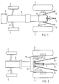
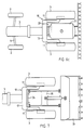
- FIG. 1 a conventional tractor is shown in a view from above.
- the chassis with the motor structure 5, the massive rear axle 8 and the rear wheel drive block 9 are clearly recognizable.
- the construction of such a tractor leads to an uneven weight distribution on the axles with approximately one third of the weight on the front and two thirds of the weight on the Rear axle 8.
- a three-point suspension with three articulated arms 17, for example which can be moved in the vertical direction with a hydraulic lifting device (not shown)
- this must inevitably be arranged behind the rear wheel drive block 9.
- this leads to an additional shift in weight since an implement attached to these articulated arms 17 exerts a leverage effect on the rear axle, the front wheels 2 are relieved and thus additional weight is loaded on the rear wheels 3.
- the contact points of the rear wheels 3 will exert great pressure on the soil and destroy the earth structure, that is to say both the capillarity of the soil and small and smallest soil organisms.
- the additional weights 19 in the front area of the tractor which are often provided to increase the stability or better steerability of the tractor, do not change the heavy load on the rear wheels 3 and are not able to relieve them. Rather, the total weight of the tractor is increased, which leads to an additional load on the ground.
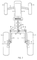
- FIG 2 a tractor according to the invention is shown schematically from above. Similar to conventional tractors, a motor structure 5 with a motor 7 is present here. A gear block 14 is indicated schematically.
- the vehicle can have both a mere rear-wheel drive and an all-wheel drive.
- the two rear wheels 3 are not, as is generally the case, mounted on a rigid, common drive axle, but are mounted on two lateral legs or longitudinal spars 11 of a rear wheel attachment 10.
- a conventional axle arrangement is therefore no longer available, but this rear wheel attachment takes over both functions of a chassis and an axle.
- This wheel attachment 10 preferably contains a cross bar construction 12 and two lateral longitudinal bars 11 and overall has an essentially U-shaped shape.
- the crossbar construction 12 is rigid with the rear ren end 13 of the vehicle chassis connected.
- Both the cross bar construction 12 and the longitudinal bars 11 are hollow on the inside and are designed as a torsion-resistant, load-bearing housing.
- the two rear wheels are mounted on the free ends of the longitudinal spars 11 and are driven by a drive 15 provided inside the wheel attachment 10.
- the cavity of the crossbar construction 12 offers enough space for a cross gear 14 (ring gear and differential).
- the width of the crossbar construction 12 determines the spacing of the rear wheels 3.
- the U-shaped wheel attachment 10 is preferably arranged horizontally, ie approximately parallel to a horizontal plane.
- the two lateral longitudinal spars or legs 11 are so long that their starting point on the vehicle chassis or on the transverse spar structure 12 lies in front of or in the region of the front edges of the rear wheels 3.
- the free space 1 between the rear wheels can be determined by a suitable choice of the length of the longitudinal spars or legs 11 and by their lateral spacing, 10 practical limits being given because of the loads occurring during the journey and the material thickness of the wheel fastening required as a result.
- the wheelbase is approximately the same as in conventional tractors, although the longitudinal spars or legs 11 projecting to the rear are provided. This is possible because up to now the clutch housing has been extended and other components have been dimensioned too large to achieve the necessary overall length of the tractors.
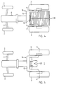
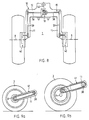
- Figure 3 shows an embodiment of a tractor with a three-point hitch for the assembly of agricultural equipment, for example.
- a support profile 16 On a support profile 16, three articulated arms 17 are articulated.
- FIG. 1 in which a conventional tractor with three-point suspension is shown, shows that, with respect to the wheel axles, the position of the implements (not shown) which are fastened to the free ends of the articulated arms 17 have longer articulated arms for use in the tractor according to the invention come.
- This has the advantage that a much greater freedom of movement is achieved, i.e. Both the lateral swiveling option and the movement in the vertical direction are increased.
- FIG. 4 shows an embodiment of a tractor with a novel drive option for the use of the tractor with high tensile loads.
- a drive caterpillar 20 is coupled, which essentially lies between the two rear wheels 3.
- a thrust unit according to European patent application No. 85107772.7 with a drive also described there is used.
- This caterpillar or the thrust unit 20 is placed in the longitudinal direction of the vehicle so that its central axis with the Hin terrace roof line coincides or is approximately at these. This ensures that the steerability of the vehicle is not impaired, since when the vehicle is steered and turned, both the rear wheels and the drive crawler 20 lie essentially on a common line running transversely to the direction of travel.
- the relatively light tractor can be converted into a powerful and very powerful tractor in the shortest possible time.
- This is particularly advantageous for agriculture, since tractors are required for a wide variety of uses and for this reason, two tractors have so far been required to cover all areas of work.
- the soil can be compacted by using the caterpillar. Since the caterpillar can be made with a total height of only approx. 50 cm, it is possible to use additional devices such as three-point suspensions, trailer couplings, rear loading shovels etc. at the same time.
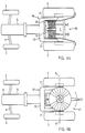
- FIG. 5 shows the subject matter of the invention with a fifth wheel coupling 22.
- the advantage of the rear wheel attachment according to the invention is that heavy single-axle trailers, such as loading wagons, can not be coupled and supported behind the rear wheel axle of the tractor as before, but rather above or, as can be seen in the figure, in front of the drive axle line 8. In this way, a much larger fifth wheel load can be absorbed by the pulling tractor without relieving the load on its front axle 4 and making the vehicle unable to steer. It is also possible to relieve the load on the axle of the trailer, by transferring a load to the tractor. This improved distribution of the axle loads results in an overall increase in traffic safety through improved driving behavior and braking power of the tractor in fast driving, especially in road traffic.
- FIGS. 6a, 6b and 6c show a vehicle according to the invention with mounted work equipment.
- the three examples shown show that the space between the rear wheels 3 can be used for the often voluminous and heavy work tools.
- a double cable winch 24, as used for example in forestry, is attached to the rear end 13 of the tractor by means of a suspension device 25.
- the center of gravity of the often heavy cable winches comes in front of the imaginary rear wheel axle and leads to an even weight distribution on the front and rear wheels.
- a better power transmission of the tensile load to the tractor is achieved, so that a much greater torque than previously can be transmitted via the wheels, which is particularly important with heavy tensile loads or on gradients.
- FIG. 6b Another possible application is shown in FIG. 6b.
- the weight of the fertilizer spreader rests directly on or in front of the axle of the rear wheels, which also leads to good driving behavior.
- a field sprayer 29, as shown in FIG. 6c can be attached to the tractor.
- the spray liquid tank 31 with a few hundred to over a thousand liter content comes to be in a favorable position in the area between the rear wheels 3.
- the overall length of the tractor with attached sprayer can also be reduced compared to conventional vehicle / implement combinations, thereby achieving greater maneuverability.
- the construction according to the invention can achieve a significantly lower overall height by ideally utilizing the space between the large rear wheels.
- FIG. 7 shows a tractor according to the invention with a rear loading shovel 33 attached.
- the front loader which has so far been subject to many disadvantages, can be replaced by a better and more powerful construction.
- a hydraulically movable suspension device 35 is attached to the rear of the tractor chassis by means of a mounting device 34.
- a drive caterpillar 20 (FIG. 4) can also be used here simultaneously with the loading shovel. This enables excavation work to be carried out in a similar manner to that of construction machinery. Such work was not possible with conventional front loaders because of the loads caused by the weight distribution. There is also the possibility to use much larger buckets compared to front loaders and thus to significantly increase the loading capacity or the cubic meter capacity.
- the free space between the rear wheels enables the coupling of additional auxiliary devices or tools or the coupling of trailers or other machines. It is also possible to build any other bulky loads, devices or loading platforms between the rear wheels.
- the mounting devices, couplings or other auxiliary devices can be provided directly on the vehicle chassis or on the wheel attachment 10.
- the wheel attachment 10 can also have a shape that differs from the U shape.
- the crossbar construction can be dispensed with and two legs 11 starting from one point can be provided.
- the cross bar construction 12 can be made even wider and more stable for special applications, so that the rearward extending longitudinal bars 11 lie on the outside of the rear wheels and their wheel axles 8 are supported in these longitudinal bars 11 and are directed inwards. This makes it possible to attach or support tools or auxiliary devices on the outside of the rear wheels on the longitudinal spars 11.
- the longitudinal spars 11 can also be forked at their free end, the rear wheels each lying between these forks.
- the wheel attachment 10 can also be inclined with respect to the horizontal position and, for example, run obliquely to the rear.
- the cross member can with a corresponding design of the chassis The mechanical construction is not required or integrated into the chassis and the longitudinal spars are attached directly to the chassis.
- a possible drive 15 of the rear wheels 3 is shown schematically in FIG. 8.
- a transverse gear (ring gear and differential) 18 which is connected to the motor 7 via a drive shaft 40 and a manual transmission 14 (cf. FIG. 1).
- the two rear wheels 3 are driven via shafts 38 and further drive elements 39, preferably a chain drive.
- a reduction 42 is provided at the ends of the longitudinal spars 11. This reduction is preferably arranged such that it projects into the free area of the rear wheels 3.
- FIGS. 9a and 9b Two possible design variants of chain drives 41 are shown in FIGS. 9a and 9b. Since the longitudinal spars 11 are exposed to greater loads, in particular when driving on uneven terrain, and warping can occur as a result, the use of chain drives is advantageous. As a result, the mechanical loads during the power transmission from the shafts 38 to the rear wheel axles 8 can be avoided or compensated for. In addition, such chain drives have relatively low power losses of approximately 1%. Chains with an internal pinion (Fig. 9b) or a planetary gear (Fig. 9a) can be used.
- a gear drive 42 as shown in FIG. 10, can also be used to drive the rear wheels 3.
- the force transmission from the shafts 38 to the rear wheel axles 8 takes place through a plurality of spur gears 45.
- Another embodiment variant of the invention uses a hydrostatic drive for the rear wheels 3 or, in the case of an all-wheel drive, also for the front wheels.
- the necessary connecting lines are routed inside the rear wheel fastening 10 or, if need be, along this to the corresponding reductions 42.
- both the transmission housing and the rear wheel attachment 10 and the drive 15 are of lightweight construction. This enables a low overall weight of the vehicle. Since the weight distribution due to the rear wheel fastening 10 according to the invention no longer bears primarily on the rear wheels as before, the tractive effort is not impaired by a small vehicle weight. For large pulling capacities there is also the possibility of an additional thrust unit mentioned above.
Abstract
Die Erfindung betrifft ein Zug- oder Lastfahrzeug, insbesondere einen Traktor, mit Hinterrad- oder Allradantrieb. Die Hinterräder sind an zwei vom Fahrzeugheck im Abstand voneinander nach hinten ragenden Längsholmen oder Schenkeln (11) einer Hinterradbefestigung (10) gelagert. Die Hinterradbefestigung (10) ist im wesentlichen U-förmig ausgebildet und enthält eine Antriebsvorrichtung (15). Zwischen den Hinterrädern liegt dabei ein das Ankoppeln von Hilfsvorrichtungen und Aggregaten (17, 20, 22, 24, 27, 31, 33) erlaubender Freiraum (1).The invention relates to a tractor or truck, in particular a tractor, with rear-wheel or all-wheel drive. The rear wheels are mounted on two longitudinal spars or legs (11) of a rear wheel attachment (10) which project from the rear of the vehicle to the rear at a distance from one another. The rear wheel attachment (10) is essentially U-shaped and contains a drive device (15). Between the rear wheels there is a free space (1) allowing the coupling of auxiliary devices and units (17, 20, 22, 24, 27, 31, 33).
Description
Die Erfindung betrifft ein Zug- bzw. Lastfahrzeug gemäss dem Oberbegriff des Patentanspruches 1.The invention relates to a tractor or truck according to the preamble of
Zugfahrzeuge, insbesondere Traktoren für die Land- oder Forstwirtschaft, werden seit Jahrzehnten eingesetzt. 0bwohl die Anforderungen an diese Fahrzeuge und deren Einsatzbereiche erhebliche Wandlungen durchlaufen haben, wurde die althergebrachte Konstruktionsweise von solchen Traktoren bis heute im wesentlichen beibehalten.Traction vehicles, especially tractors for agriculture or forestry, have been used for decades. Although the requirements for these vehicles and their areas of application have undergone significant changes, the traditional design of such tractors has largely been retained to this day.
War ursprünglich ein relativ hohes Eigengewicht der Traktoren noch erwünscht, da diese als reine Zugfahrzeuge eingesetzt wurden und somit die Hinterachse ausreichend belastet sein musste, so stellte sich in neuerer Zeit, insbesondere nach dem Aufkommen von direkt am Traktor aufgehängten Geräten, das Gewicht des Traktors und die Gewichtsverteilung als nachteilig heraus. Mittels Dreipunktaufhängungen bzw. hydraulischen Hebevorrichtungen werden heutzutage eine Vielzahl von Maschinen direkt hinten am Traktor angekoppelt und können im Betrieb auf den Boden abgesenkt oder während der Fahrt angehoben werden. Diese Arbeitsgeräte weisen zum Teil ein erhebli ches Eigengewicht auf und führen damit zu einer zusätzlichen Belastung der Hinterachse des Traktors.Originally, a relatively high weight of the tractors was still desirable, since they were used as pure towing vehicles and the rear axle had to be sufficiently loaded, but in recent times, especially after the advent of implements directly attached to the tractor, the weight of the tractor and the weight distribution as disadvantageous. Nowadays, a large number of machines are coupled directly to the rear of the tractor using three-point suspensions or hydraulic lifting devices and can be lowered to the ground during operation or raised while driving. Some of these tools have a considerable amount weight and thus lead to an additional load on the rear axle of the tractor.
Werden sehr schwere Arbeitsgeräte hinten am Traktor aufgehängt, so besteht die Gefahr, dass dadurch eine Hebelwirkung und damit eine ungünstige Gewichtsverlagerung erfolgt, die zu einem Abheben der Vorderachse führen kann. Die heute übliche Gegenmassnahme besteht darin, dass zusätzliche Gewichte im Bereich der Traktor-Vorderachse angebracht werden und damit die vordere Achslast erhöht wird. Wohl vermag dies den Traktor zu stabilisieren und ein Abheben der Vorderachse zu verhindern, doch wird gleichzeitig das Gesamtgewicht des Traktors zusätzlich erhöht und damit ein sehr grosser Bodendruck verursacht. Oft wird wegen des grossen Gesamtgewichts ein Allradantrieb erforderlich um die Zugleistung zu erhöhen, doch vermag dieser das Zugvermögen nur unbedeutend zu verbessern, weil entsprechend der kurzen Bauweise von solchen Traktoren das Gewicht des Fahrzeuges wegen des Zugmomentes und der Gewichtsverteilung im Betrieb auf die hintere Achse verlagert wird.If very heavy implements are hung on the rear of the tractor, there is a risk that this will result in a leverage effect and thus an unfavorable shift in weight, which can lead to the front axle lifting off. The usual countermeasure today is that additional weights are attached in the area of the tractor front axle, thus increasing the front axle load. This may stabilize the tractor and prevent the front axle from lifting, but at the same time the total weight of the tractor is additionally increased, causing a very high ground pressure. Often, due to the large overall weight, all-wheel drive is required to increase the tractive power, but this can only slightly improve the tractive power because, due to the short design of such tractors, the weight of the vehicle is shifted to the rear axle due to the pulling torque and the weight distribution during operation becomes.
Als Folge des Gewichts von Traktor und Zusatzgeräten und der damit verbundenen grossen Belastung insbesondere der Hinterachse wird der Boden entlang der Reifenspur stark zusammengepresst und geschädigt. Die Tätigkeit der Bodenlebewesen und Bakterien wird dadurch gestört und das Feld wird zusammengekarrt, so dass eine mangelnde Sauerstoffversorgung und ein gestörter Wasserhaushalt des Bodens resultieren. Wegen der zerstörten Kapillarität des Bodens ist der Wasserabfluss bei Regen und der Wasseraufstieg während Schönwetterperioden beeinträchtigt. Diese übermässige Belastung des Bodens führt letztlich dazu, dass das Pflanzenwachstum gestört ist, ein niedrigerer Ertrag erzielt wird und vermehrte Düngung sowie Schädlingsbekämpfungsmittel nötig werden. Damit wird eine zusätzliche Umweltbelastung verursacht, die durch Einsatz geeigneter Traktoren und Arbeitsgeräte vermieden werden könnte. Ausserdem ist das Fahrverhalten der so konstruierten Fahrzeuge sehr ungünstig und gefährlich; dies gilt wegen der ungenügenden Belastung der Vorderachse und damit schlechten Lenkbarkeit des Fahrzeuges insbesondere bei schneller Fahrt auf der Strasse.As a result of the weight of the tractor and additional equipment and the associated high load, particularly on the rear axle, the ground along the tire track is strongly compressed and damaged. The activity of soil organisms and bacteria is thereby disturbed and the field is carted together, resulting in a lack of oxygen supply and a disturbed water balance in the soil. Because of the destroyed capillarity of the soil, the water drainage during rain and the water rise during periods of good weather are impaired. This excessive soil load ultimately leads to plant growth being disrupted, lower yields being achieved and increased fertilization and pesticides becoming necessary. This causes an additional environmental impact, which is caused by the use of suitable tractors and tools could be avoided. In addition, the driving behavior of the vehicles constructed in this way is very unfavorable and dangerous; this applies because of the insufficient load on the front axle and thus poor maneuverability of the vehicle, especially when driving fast on the road.
Es ist Aufgabe der Erfindung, ein Zug- bzw. Lastfahrzeug zu schaffen, welches durch geeignete Gewichtsverteilung und Belastung der Hinterräder ein sicheres Fahrverhalten gewährleistet, ein geringes Gesamtgewicht von Fahrzeug und Arbeitsgeräten aufweist und bei hoher Wendigkeit und kleinen Abmessungen eine geringe Belastung des Bodens mit sich bringt.It is an object of the invention to provide a towing vehicle or load vehicle which ensures safe driving behavior by suitable weight distribution and loading of the rear wheels, has a low overall weight of vehicle and working equipment and, with high maneuverability and small dimensions, has a low load on the ground brings.
Diese Aufgabe wird durch die im kennzeichnenden Teil des Patentanspruches 1 genannten Merkmale gelöst.This object is achieved by the features mentioned in the characterizing part of
Das erfindungsgemässe Zugfahrzeug weist eine Hinterradbefestigung mit zwei Schenkeln oder Längsholmen auf. Diese Hinterradbefestigung besteht vorzugsweise aus einer Querholmenkonstruktion und zwei die Räder tragende Längsholmen, die U-förmig angeordnet sind. Sie liegt vorzugsweise in einer im wesentlichen horizontalen Ebene und ist so orientiert, dass die Querholmenkonstruktion am hinteren Ende des Fahrzeugchassis befestigt ist und die beiden Längsholmen seitlich und parallel zur Fahrtrichtung nach hinten ragen. Die beiden Hinterräder sind an den freien Enden dieser beiden Längsholmen angebracht, so dass dementsprechend zwischen den Rädern ein Freiraum besteht. Dadurch wird es möglich ein Arbeitsgerät und/oder andere Vorrichtungen so am Fahrzeug anzukoppeln zu befestigen oder anzuhängen, dass deren Schwerpunkte vor oder nur knapp hinter die Hinterradachslinie zu liegen kommt. Dadurch kann eine Entlastung der Hinterräder und eine optimale Gewichtsverteilung bewirkt werden. Gleichzeitig werden dadurch völlig neue Möglichkeiten für den Einsatz von Arbeitsgeräten oder zusätzlichen Antriebsvorrichtungen geschaffen. Die Vorteile der Erfindung kommen insbesondere bei einer kurzen Bauweise des Zugfahrzeuges zum tragen, da dann die Gefahr eines Abhebens der Vorderachse besonders akut ist. Diese verbesserte Verteilung der Achslasten bringt des weiteren eine Erhöhung der Verkehrssicherheit durch ein verbessertes Fahrverhalten des Traktors in schneller Fahrt, insbesondere im Strassenverkehr, mit sich.The towing vehicle according to the invention has a rear wheel attachment with two legs or longitudinal spars. This rear wheel attachment preferably consists of a cross bar construction and two longitudinal bars supporting the wheels, which are arranged in a U-shape. It is preferably in a substantially horizontal plane and is oriented so that the crossbar construction is attached to the rear end of the vehicle chassis and the two longitudinal bars project laterally and parallel to the direction of travel to the rear. The two rear wheels are attached to the free ends of these two longitudinal spars, so that there is accordingly a free space between the wheels. This makes it possible to attach or attach a working device and / or other devices to the vehicle in such a way that their center of gravity comes in front of or only just behind the rear wheel axle line. This can relieve the rear wheels and optimal weight distribution. At the same time, completely new possibilities are created for the use of work equipment or additional drive devices. The advantages of the invention are particularly evident in the short construction of the towing vehicle, since the danger of the front axle lifting off is particularly acute. This improved distribution of the axle loads also brings about an increase in traffic safety through an improved driving behavior of the tractor in fast driving, in particular in road traffic.
Ausführungsbeispiele der Erfindung sind anhand der nachfolgenden Zeichnungen näher beschrieben.
- Fig. 1 zeigt einen Traktor herkömmlicher Bauweise
- Fig. 2 zeigt einen erfindungsgemässen Traktor mit U-förmiger Hinterradbefestigung
- Fig. 3 zeigt einen Traktor mit U-förmiger Hinterradbefestigung und einer Dreipunktaufhängung
- Fig. 4 zeigt einen Traktor mit U-förmiger Hinterradbefestigung und einem zusätzlichen Antriebsraupe
- Fig. 5 zeigt einen Traktor mit U-förmiger Hinterradbefestigung und einer vor der Hinterradachslinie liegenden Sattelkupplung
- Fig. 6a zeigt einen Traktor mit U-förmiger Hinterradbefestigung und einer zwischen den Hinterrädern aufgehängten Doppelseilwinde
- Fig. 6b zeigt einen Traktor mit U-förmiger Hinterradbefestigung und einem zwischen den Hinterrädern montierten Düngerstreuer
- Fig. 6c zeigt einen Traktor mit U-förmiger Hinterradbefestigung und einer zwischen den Hinterrädern aufgehängten Feldspritze
- Fig. 7 zeigt einen Traktor mit U-förmiger Hinterradbefestigung und einer Heck-Ladeschaufel
- Fig. 8 zeigt die Hinterradbefestigung mit einem integrierten Antrieb im Querschnitt
- Fig. 9a zeigt einen Längsschnitt durch einen Hinterradantrieb mit einer Kette mit im Rad integrierter Planetenuntersetzung
- Fig. 9b zeigt einen Längsschnitt durch einen hinterradantrieb mit einer Kette und einer Untersetzung mittels Innenritzel
- Fig. 10 zeigt einen Längsschnitt durch einen Hinterradantrieb mit Zahnrädern
- Fig. 1 shows a tractor of conventional design
- Fig. 2 shows a tractor according to the invention with a U-shaped rear wheel attachment
- Fig. 3 shows a tractor with a U-shaped rear wheel attachment and a three-point suspension
- Fig. 4 shows a tractor with a U-shaped rear wheel attachment and an additional drive caterpillar
- Fig. 5 shows a tractor with a U-shaped rear wheel attachment and a fifth wheel located in front of the rear wheel axle line
- 6a shows a tractor with a U-shaped rear wheel attachment and a double cable winch suspended between the rear wheels
- Fig. 6b shows a tractor with a U-shaped rear wheel attachment and a fertilizer spreader mounted between the rear wheels
- Fig. 6c shows a tractor with a U-shaped rear wheel attachment and a sprayer suspended between the rear wheels
- Fig. 7 shows a tractor with a U-shaped rear wheel attachment and a rear loading shovel
- Fig. 8 shows the rear wheel attachment with an integrated drive in cross section
- 9a shows a longitudinal section through a rear wheel drive with a chain with a planetary gear reduction integrated in the wheel
- Fig. 9b shows a longitudinal section through a rear wheel drive with a chain and a reduction by means of an internal pinion
- Fig. 10 shows a longitudinal section through a rear wheel drive with gears
Obwohl im folgenden bei der Erfindungsbeschreibung im wesentlichen nur auf einen Traktor Bezug genommen wird, ist der erfindungsgemässe Aufbau des Fahrzeuges für alle Arten von Zug- und Lastfahrzeugen einsetzbar.Although essentially only a tractor is referred to in the description of the invention below, the construction of the vehicle according to the invention can be used for all types of tractor and truck vehicles.
In Figur 1 ist ein herkömmlicher Traktor in der Ansicht von oben dargestellt. Gut erkennbar ist das Chassis mit dem Motoraufbau 5, die massive Hinterachse 8 und der Hinterradantriebsblock 9. Die Konstruktion eines solchen Traktors führt zu einer ungleichen Gewichtsverteilung auf die Achsen mit ca. einem Drittel des Gewichtes auf der Vorder- und zwei Dritteln des Gewichtes auf der Hinterachse 8. Wird, wie dies in Figur 1 ersichtlich ist, beispielsweise eine Dreipunktaufhängung mit drei Gelenkarmen 17, welche mit einer nicht näher dargestellten hydraulischen Hebevorrichtung in vertikaler Richtung bewegt werden kann, vorgesehen, so muss diese zwangsläufig hinter dem Hinterradantriebsblock 9 angeordnet werden. Dies führt jedoch zu einer zusätzlichen Gewichtsverlagerung, da ein an diesen Gelenkarmen 17 befestigtes Arbeitsgerät eine Hebelwirkung bezüglich der Hinterachse ausübt, die Vorderräder 2 entlastet werden und damit zusätzliches Gewicht auf den Hinterrädern 3 lastet. Als Folge davon werden die Auflagepunkte der Hinterräder 3 einen grossen Druck auf das Erdreich ausüben und die Erdstruktur, d.h. sowohl die Kapillarität des Bodens als auch kleine und kleinste Bodenlebewesen zerstören. Die oft zur Erhöhung der Stabilität bzw. zur besseren Lenkbarkeit des Traktors vorgesehenen Zusatzgewichte 19 im Frontbereich des Traktors ändern dabei nichts an der starken Belastung der Hinterräder 3 und vermögen diese nicht zu entlasten. Vielmehr wird dadurch das Gesamtgewicht des Traktors erhöht, was zu einer zusätzlichen Bodenbelastung führt.In Figure 1, a conventional tractor is shown in a view from above. The chassis with the
In Figur 2 ist ein erfindungsgemässer Traktor schematisch von oben dargestellt. Ähnlich wie bei herkömmlichen Traktoren ist hier ein Motoraufbau 5 mit einem Motor 7 vorhanden. Ein Getriebeblock 14 ist schematisch angedeutet. Das Fahrzeug kann sowohl einen blossen Hinterrad- als auch einen Allradantrieb besitzen. Die beiden Hinterräder 3 sind nicht wie allgemein üblich auf einer starren, gemeinsamen Antriebs -Achse gelagert, sondern sind an zwei seitlichen Schenkeln oder Längsholmen 11 einer Hinterradbefestigung 10 gelagert. Eine herkömmliche Achsanordnung ist mithin nicht mehr gegeben, sondern diese Hinterradbefestigung übernimmt sowohl Funktionen eines Chassis als auch einer Achse. Diese Radbefestigung 10 enthält vorzugsweise eine Querholmenkonstruktion 12 und zwei seitliche Längsholmen 11 und weist insgesamt eine im wesentlichen U-förmige Gestalt auf. Die Querholmenkonstruktion 12 ist starr mit dem hinte ren Ende 13 des Fahrzeugchassis verbunden. Sowohl die Querholmenkonstruktion 12 als auch die Längsholmen 11 sind innen hohl und sind als verwindungsfestes, tragfähiges Gehäuse ausgebildet. Die beiden Hinterräder sind an den freien Enden der Längsholmen 11 gelagert und werden über einen im Innern der Radbefestigung 10 vorgesehenen Antrieb 15 angetrieben. Der Hohlraum der Querholmenkonstruktion 12 bietet dabei genügend Platz für einen Quergetriebe 14 (Tellerrad und Differential). Die Breite der Querholmenkonstruktion 12 bestimmt dabei den Abstand der Hinterräder 3. Zwischen den Hinterrädern bleibt dank den seitlichen, im Abstand voneinander nach hinten ragenden Längsholmen 11 ein Freiraum 1 bestehen, der im dargestellten Beispiel im Grundriss ungefähr rechteckig ist. Die U-förmige Radbefestigung 10 ist vorzugsweise liegend, d.h. annähernd parallel zu einer horizontalen Ebene angeordnet. Die beiden seitlichen Längsholmen oder Schenkel 11 sind so lang, dass ihr Ansatzpunkt am Fahrzeugchassis oder an der Querholmenkonstruktion 12 vor oder im Bereich der Vorderkanten der Hinterräder 3 liegt. Der Freiraum 1 zwischen den Hinterrädern kann durch geeignete Wahl der Länge der Längsholmen oder Schenkel 11 und durch deren seitlichen Abstand bestimmt werden, wobei wegen den bei der Fahrt auftretenden Belastungen und der dadurch erforderlichen Materialstärke der Radbefestigung 10 praktische Limiten gegeben sind. Der Radstand beträgt ungefähr gleich viel wie bei herkömmlichen Traktoren, obwohl die nach hinten ragenden Längsholmen oder Schenkel 11 vorgesehen sind. Dies ist möglich, da bisher das Kupplungsgehäuse verlängert und auch weitere Bauteile zu gross dimensioniert wurden, um die notwendige Baulänge der Traktoren zu erreichen. Da bei dem erfindungsgemässen Traktor jedoch eine kompakte Bauweise angestrebt wird, kann auf ein grosses Kupplungsgehäuse verzichtet und damit der gewohnte Radstand erzielt werden. Der zwischen den Hinterrädern liegende Freiraum 1 ermöglicht den An- bzw. Aufbau von Arbeitsgeräten oder anderen Vorrichtungen oder das Ankuppeln von Zusatzgeräten oder Anhängern. Diese Konstruktionsweise erlaubt ein Verschieben des Schwerpunktes der so vorgesehenen Geräte oder Gewichte in Fahrtrichtung und bewirkt damit eine gleichmässigere Gewichtsverteilung auf Vorder- und Hinterachse des Fahrzeuges.In Figure 2, a tractor according to the invention is shown schematically from above. Similar to conventional tractors, a
Figur 3 zeigt ein Ausführungsbeispiel eines Traktores mit einer Dreipunktaufhängung für die Montage von beispielsweise Landwirtschaftsgeräten. An einem Trägerprofil 16 sind drei Gelenkarme 17 gelenkig befestigt. Ein Vergleich mit Figur 1, in welcher ein herkömmlicher Traktor mit Dreipunktaufhängung dargestellt ist, lässt erkennen, dass bei bezüglich den Radachsen gleicher Lage der nicht näher dargestellten Arbeitsgeräte, welche an den freien Enden der Gelenkarme 17 befestigt werden, beim erfindungsgemässen Traktor längere Gelenkarme zum Einsatz kommen. Dies hat den Vorteil, dass eine wesentlich grössere Bewegungsfreiheit erzielt wird, d.h. sowohl die seitliche Ausschwenkmöglichkeit als auch die Bewegung in vertikaler Richtung werden erhöht. Dadurch besteht nun auch die Möglichkeit, lange Geräte oder Gerätekombinationen mittels einer hier nicht dargestellten hydraulischen Hebevorrichtung hoch anzuheben, was bisher mangels genügender Bewegungsfreiheit unmöglich war. Der Einsatz von langen Gelenkarmen hätte bei herkömmlichen Traktoren zur Folge, dass die Arbeitsgeräte weit hinter das Fahrzeug zu liegen kämen und dieses damit erheblich an Wendigkeit sowie Fahrstabilität einbüssen würde.Figure 3 shows an embodiment of a tractor with a three-point hitch for the assembly of agricultural equipment, for example. On a
Figur 4 zeigt ein Ausführungsbeispiel eines Traktors mit einer neuartigen Antriebsmöglichkeit für den Einsatz des Traktors bei grossen Zugbelastungen. Am hinteren Ende 13 des Fahrzeugchassis wird eine Antriebsraupe 20 angekoppelt, welche im wesentlichen zwischen die beiden Hinterräder 3 zu liegen kommt. Dabei wird beispielsweise eine Schubaggregat entsprechend der europäischen Patentanmeldung Nr. 85107772.7 mit einem dort ebenfalls beschriebenen Antrieb verwendet. Diese Raupe bzw. das Schubaggregat 20 ist in Längsrichtung des Fahrzeuges so plaziert, dass dessen mittlere Achse mit den Hin terradachslinie zusammenfällt oder annähernd bei diesen liegt. Damit ist gewährleistet, dass die Lenkbarkeit des Fahrzeuges nicht beeinträchtigt ist, da beim Lenken und Drehen des Fahrzeuges sowohl die Hinterräder als auch die Antriebsraupe 20 im wesentlichen auf einer gemeinsamen, quer zur Fahrtrichtung verlaufenden Linie liegen. Durch Verwendung einer solchen Antriebsraupe 20 kann der relative leichte Traktor in kürzester Zeit zu einem leistungsstarken und sehr zugkräftigen Traktor umgerüstet werden. Dies bringt insbesondere für die Landwirtschaft grosse Vorteile, da hier von Traktoren sehr vielfältige Einsatzmöglichkeiten gefordert werden und aus diesem Grunde bis anhin meist zwei Traktoren benötigt wurden um alle Arbeitsbereiche abzudecken. Durch die zusätzliche Auflagefläche der Antriebsraupe 20 kann der maximale Bodendruck, der auf den Hinterrädern lastet, reduziert werden und gleichzeitig das Zugvermögen gesteigert werden, was insbesondere beim Pflügen, Eggen oder bei schweren Erntearbeiten vorteilhaft ist. Bei heiklen Arbeiten, wie z.B. die Saatbeetaufbereitung, kann durch die Verwendung der Raupe eine Verdichtung des Bodens vermieden werden. Da die Raupe mit einer Gesamthöhe von nur ca. 50 cm ausgeführt werden kann, besteht die Möglichkeit, gleichzeitig zusätzliche Geräte wie beispielsweise Dreipunktaufhängungen, Anhängerkupplungen, Heckladeschaufeln etc. zu verwenden.Figure 4 shows an embodiment of a tractor with a novel drive option for the use of the tractor with high tensile loads. At the
In Figur 5 ist der Erfindungsgegenstand mit einer Sattel-Kupplung 22 dargestellt. Der Vorteil der erfindungsgemässen Hinterradbefestigung besteht darin, dass schwere Einachsanhänger, wie beispielsweise Ladewagen, nicht wie bisher hinter der Hinterradachse des Traktors, sondern über dieser oder sogar, wie dies in der Abbildung ersichtlich ist, vor den Antriebsachslinie 8 angekoppelt und abgestützt werden konnen. Auf diese Weise kann eine wesentlich grössere Sattellast vom ziehenden Traktor aufgenommen werden, ohne dass dessen Vorderachse 4 entlastet und das Gefährt dadurch lenkungsunfähig würde. Zudem ist es möglich, die Achse des Anhängers zu entlasten, indem eine Lastübertragung auf den Traktor erfolgt. Diese verbesserte Verteilung der Achslasten bringt insgesamt eine Erhöhung der Verkehrssicherheit durch ein verbessertes Fahrverhalten sowie Bremsvermögen des Traktors in schneller Fahrt, insbesondere im Strassenverkehr, mit sich.5 shows the subject matter of the invention with a
Figur 6a, 6b und 6c zeigen ein erfindungsgemässes Fahrzeug mit aufgebauten Arbeitsgeräten. In den drei dargestellten Beispielen ist ersichtlich, dass der zwischen den Hinterrädern 3 vorhandene Freiraum für die oft voluminösen und schweren Arbeitsgeräte genutzt werden kann. Eine Doppelseilwinde 24, wie sie beispielsweise in der Forstwirtschaft verwendet wird, ist mittels einer Aufhängevorrichtung 25 am hinteren Ende 13 des Traktores befestigt. Der Schwerpunkt der oft schweren Seilwinden kommt dadurch vor die imaginäre Hinterradachse zu liegen und führt zu einer gleichmässigen Gewichtsverteilung auf die Vorder- und Hinterräder. Gleichzeitig wird eine bessere Kraftübertragung der Zuglast auf den Schlepper erreicht, so dass im Einsatz ein wesentlich grösseres Drehmoment als bis anhin über die Räder übertragen werden kann, was insbesondere bei schweren Zuglasten oder in Steigungen von Bedeutung ist.FIGS. 6a, 6b and 6c show a vehicle according to the invention with mounted work equipment. The three examples shown show that the space between the
Eine weitere Einsatzmöglichkeit ist in Figur 6b dargestellt. Hier liegt ein Düngerstreuer 27 zwischen den beiden Hinterrädern 3. Der vielfach im beladenen Zustand bis über 500 Kilo schwere Streuer 27 muss nicht mehr wie bisher weit hinter der Radachse montiert werden. Dadurch entfallen auch die Zusatzgewichte 19 (Fig. 1), die üblicherweise an der Front 6 des Traktors angebracht werden mussten, da wegen der in Fahrtrichtung nach vorne versetzten Lage des Streuer-Schwerpunktes keine Hebelwirkung bezüglich der Hinterradachse auftritt. Das Gewicht des Düngerstreuers lastet direkt auf oder vor der Achse der Hinterräder, was gleichzeitig zu einem guten Fahrverhalten führt.Another possible application is shown in FIG. 6b. Here is a
In ähnlicher Weise kann eine Feldspritze 29, wie sie in Figur 6c dargestellt ist, am Traktor angebracht werden. Der Spritzbrühebehälter 31 mit einigen hundert bis über tausend Liter Inhalt kommt in eine günstige Lage im Bereich zwischen den Hinterrädern 3 zu liegen. Neben der durch die bessere Gewichtsverteilung bewirkten Verringerung des Bodendruckes kann auch die Gesamtlänge des Traktors mit angebauter Feldspritze gegenüber herkömmlichen Fahrzeug-Geräte-Kombinationen verringert und dadurch eine grössere Wendigkeit erreicht werden. Gegenüber den bisher zur besseren Lastverteilung zum Teil verwendeten Fahrzeugen mit Ladebrücken oder ähnlichen Aufbauten für den Aufbau von Arbeitsgeräten über der Hinterradachse kann durch die erfindungsgemässe Bauweise eine wesentlich geringere Gesamthöhe erreicht werden, indem der Raum zwischen den grossen Hinterrädern in idealer Weise ausgenützt wird.In a similar manner, a
Figur 7 zeigt einen erfindungsgemässen Traktor mit einer angebauten Heck-Ladeschaufel 33. Bei herkömmlichen Traktoren war der Anbau einer solchen Ladeschaufel hinter dem Traktor wegen des Achsblockes 9 (Fig. 1) nicht möglich. Der mit vielen Nachteilen behaftete bisher übliche Frontlader kann dank der Erfindung durch eine bessere und leistungsfähigere Konstruktion ersetzt werden. Mittels einer Montagevorrichtung 34 wird eine hydraulisch bewegbare Aufhängevorrichtung 35 hinten am Traktorchassis befestigt. Zur Erhöhung der Adhäsion und Verringerung des Bodendruckes kann auch hier gleichzeitig mit der Ladeschaufel eine Antriebsraupe 20 (Fig. 4) verwen det werden. Dies ermöglicht ohne weiteres Aushubarbeiten in ähnlicher Weise wie mit Baumaschinen. Solche Arbeiten waren mit herkömmlichen Frontladern wegen der durch die Gewichtsverteilung bedingten Belastungen nicht möglich. Zudem besteht die Möglichkeit gegenüber Frontladern wesentlich grössere Schaufeln zu verwenden und damit die Ladekapazität bzw. die Kubikmeter-Leistung wesentlich zu erhöhen.FIG. 7 shows a tractor according to the invention with a
Der Freiraum zwischen den Hinterrädern ermöglicht das Ankoppeln von weiteren Hilfsvorrichtungen oder Arbeitsgeräten oder das Ankuppeln von Anhängern oder anderen Maschinen. Ebenso besteht die Möglichkeit, irgendwelche andere sperrige Lasten, Geräte oder Ladepritschen zwischen den Hinterrädern aufzubauen. Dabei können die Montagevorrichtungen, Kupplungen oder sonstigen Hilfsvorrichtungen direkt am Fahrzeugchassis oder an der Radbefestigung 10 vorgesehen werden.The free space between the rear wheels enables the coupling of additional auxiliary devices or tools or the coupling of trailers or other machines. It is also possible to build any other bulky loads, devices or loading platforms between the rear wheels. The mounting devices, couplings or other auxiliary devices can be provided directly on the vehicle chassis or on the
Selbstverständlich kann die Radbefestigung 10 auch eine gegenüber der U-Form abweichende Form aufweisen. So kann insbesondere die Querholmenkonstruktion entfallen und zwei von einem Punkt ausgehende Schenkel 11 vorgesehen werden. Des weiteren kann für spezielle Anwendungen die Querholmenkonstruktion 12 noch breiter und stabiler ausgeführt sein, so dass die nach hinten ragenden Längsholmen 11 an der Aussenseite der Hinterräder liegen und deren Radachsen 8 in diesen Längsholmen 11 gelagert und nach innen gerichtet sind. Dadurch wird es möglich, Arbeitsgeräte oder Hilfsvorrichtungen auch an der Aussenseite der Hinterräder an den Längsholmen 11 zu befestigen oder abzustützen. Des weiteren können die Längsholmen 11 an ihrem freien Ende auch gegabelt sein, wobei die Hinterräder je zwischen diesen Gabeln liegen.Of course, the
Um eine ausgeglichene Belastung der Längsholmen bzw. Schenkel 11 zu erreichen und bei entsprechender Konstruktion des Fahrzeugchassis, kann die Radbefestigung 10 auch gegenüber der horizontalen Lage geneigt sein und beispielsweise schräg nach hinten verlaufen. Ausserdem kann bei entsprechender Ausgestaltung des Chassis die Querhol menkonstruktion entfallen bzw. in das Chassis integriert und die Längsholmen direkt am Chassis angesetzt sein.In order to achieve a balanced load on the longitudinal spars or
Ein möglicher Antrieb 15 der Hinterräder 3 ist schematisch in Figur 8 dargestellt. Im Innern der Querholmenkonstruktion 12 befindet sich ein Quergetriebe (Tellerrad und Differential) 18, das über eine Antriebswelle 40 und ein Schaltgetriebe 14 mit dem Motor 7 verbunden ist (vgl. Fig. 1). Über Wellen 38 und weitere Antriebselemente 39, vorzugsweise einen Kettenantrieb, erfolgt der Antrieb der beiden Hinterräder 3. Eine Untersetzung 42 ist je an den Enden der Längsholmen 11 vorgesehen. Vorzugsweise ist diese Untersetzung so angeordnet, dass sie in den freien Bereich der Hinterräder 3 hineinragt.A
Zwei mögliche Ausführungsvarianten von Kettenantrieben 41 sind in den Figuren 9a und 9b dargestellt. Da die Längsholmen 11 insbesondere beim Befahren von unebenem Gelände grösseren Belastungen ausgesetzt sind und dadurch Verwindungen auftreten können, ist der Einsatz von Kettenantrieben vorteilhaft. Dadurch können die mechanische Belastungen bei der Kraftübertragung von den Wellen 38 auf die Hinterradachsen 8 vermieden bzw. ausgeglichen werden. Ausserdem weisen solche Kettenantriebe relativ geringe Kraftverluste von ca. 1% auf. Dabei können Ketten mit Innenritzel (Fig. 9b) oder einem Planetgetriebe (Fig. 9a) zur Anwendung kommen.Two possible design variants of chain drives 41 are shown in FIGS. 9a and 9b. Since the
Bei genügender Festigkeit der Gehäusewand der Längsholmen 11 kann zum Antrieb der Hinterräder 3 auch ein Zahnradantrieb 42, wie in Figur 10 dargestellt, verwendet werden. Durch eine Mehrzahl von Stirnzahnrädern 45 erfolgt die Kraftübertragung von den Wellen 38 auf die Hinterradachsen 8.If the housing wall of the
Eine weitere Ausführungsvariante der Erfindung verwendet einen hydrostatischen Antrieb für die Hinterräder 3 oder bei einem Allradantrieb auch für die Vorderräder. Die notwendigen Verbindungsleitungen werden im Innern der Hinterradbefestigung 10 oder allenfalls entlang von diesen zu den entsprechenden Untersetzungen 42 geführt.Another embodiment variant of the invention uses a hydrostatic drive for the
Vorzugsweise werden sowohl die Getriebegehäuse und die Hinterradbefestigung 10 als auch der Antrieb 15 in Leichtbauweise ausgeführt. Dies ermöglicht ein geringes Gesamtgewicht des Fahrzeuges. Da die Gewichtsverteilung durch die erfindungsgemässe Hinterradbefestigung 10 nicht mehr wie bisher vor allem auf den Hinterrädern lastet, ist durch ein kleines Fahrzeuggewicht die Zugleistung nicht beeinträchtigt. Für grosse Zugleistungen besteht ausserdem die obenerwähnte Möglichkeit eines zusätzlichen Schubaggregates.Preferably, both the transmission housing and the
Claims (15)
Priority Applications (1)
| Application Number | Priority Date | Filing Date | Title |
|---|---|---|---|
| AT88110001T ATE84478T1 (en) | 1987-07-01 | 1988-06-23 | TRACTOR OR TRUCK WITH SPACE BETWEEN THE REAR WHEELS. |
Applications Claiming Priority (2)
| Application Number | Priority Date | Filing Date | Title |
|---|---|---|---|
| CH2497/87A CH673016A5 (en) | 1987-07-01 | 1987-07-01 | |
| CH2497/87 | 1987-07-01 |
Publications (3)
| Publication Number | Publication Date |
|---|---|
| EP0297430A2 true EP0297430A2 (en) | 1989-01-04 |
| EP0297430A3 EP0297430A3 (en) | 1989-10-18 |
| EP0297430B1 EP0297430B1 (en) | 1993-01-13 |
Family
ID=4235138
Family Applications (1)
| Application Number | Title | Priority Date | Filing Date |
|---|---|---|---|
| EP88110001A Expired - Lifetime EP0297430B1 (en) | 1987-07-01 | 1988-06-23 | Traction or load carrying vehicle provided with a free-space between the rear wheels |
Country Status (9)
| Country | Link |
|---|---|
| US (1) | US4860843A (en) |
| EP (1) | EP0297430B1 (en) |
| CN (1) | CN1030386A (en) |
| AT (1) | ATE84478T1 (en) |
| AU (1) | AU606429B2 (en) |
| CA (1) | CA1305505C (en) |
| CH (1) | CH673016A5 (en) |
| DE (1) | DE3877435D1 (en) |
| SU (1) | SU1628840A3 (en) |
Cited By (2)
| Publication number | Priority date | Publication date | Assignee | Title |
|---|---|---|---|---|
| FR2706114A1 (en) * | 1993-06-08 | 1994-12-16 | Oury Pascal | Three-wheel straddling implement carrier for crops grown in rows |
| FR2730674A1 (en) * | 1994-10-03 | 1996-08-23 | Design Performance | High performance load carrying capacity vehicle |
Families Citing this family (8)
| Publication number | Priority date | Publication date | Assignee | Title |
|---|---|---|---|---|
| US6095005A (en) | 1998-10-15 | 2000-08-01 | Ford Motor Company | Axle drivetrain having speed reduction gear unit for automotive vehicles |
| DE10329687A1 (en) * | 2003-07-02 | 2005-01-20 | Zf Friedrichshafen Ag | portal axis |
| US7284633B2 (en) * | 2004-08-05 | 2007-10-23 | Cnh America Llc | Tractor suspension with tensioned drive shaft |
| US7234562B2 (en) * | 2004-08-05 | 2007-06-26 | Cnh America Llc | C-beam suspension support |
| KR100941255B1 (en) * | 2007-10-05 | 2010-02-11 | 현대자동차주식회사 | Trailing arm mounting device of small size frame in vehicle |
| US20130062854A1 (en) * | 2011-09-14 | 2013-03-14 | Caterpillar Inc. | Torsion suspension system |
| RU2545050C1 (en) * | 2014-02-24 | 2015-03-27 | Николай Петрович Дядченко | Two-wheeled agricultural bridge |
| RU179587U1 (en) * | 2015-08-18 | 2018-05-17 | Александр Георгиевич Батт | Vehicle |
Citations (8)
| Publication number | Priority date | Publication date | Assignee | Title |
|---|---|---|---|---|
| US2994392A (en) * | 1956-04-02 | 1961-08-01 | Kosman Henry | Combined steering and drive unit for tractor wheels |
| US3154164A (en) * | 1961-10-12 | 1964-10-27 | Cochran Equipment Company | Off-highway tractor |
| CH461871A (en) * | 1967-02-23 | 1968-08-31 | Poettinger Ohg Alois | Self-propelled haymaking and transport device |
| DE2018070A1 (en) * | 1970-04-15 | 1972-03-30 | Jost, Fritz, 6660 Zweibrücken | Multipurpose motor vehicles, in particular equipment carriers |
| DE2153415A1 (en) * | 1970-10-30 | 1972-05-10 | C. van der LeIy N.V., Maasland (Niederlande) | tractor |
| DE2811370A1 (en) * | 1978-03-16 | 1979-09-20 | Messerschmitt Boelkow Blohm | Rear driven axle for utility vehicle - has independent suspension, with gearing mounted inside trailing arms |
| DE2811675A1 (en) * | 1978-03-17 | 1979-09-27 | Manfred Ing Grad Nauerz | Motor vehicle track additional road drive - has traction track and independent frame connected to vehicle |
| FR2542156A1 (en) * | 1983-03-09 | 1984-09-14 | Bobard Jeune Sa Ets | Grape harvesting machine consisting of a straddling tractor |
Family Cites Families (5)
| Publication number | Priority date | Publication date | Assignee | Title |
|---|---|---|---|---|
| DE1069416B (en) * | 1959-11-19 | Institut für Landmaschinen- und Traktorenbau, Leipzig | Motor tool carrier | |
| US1327376A (en) * | 1917-12-29 | 1920-01-06 | Delieuvin Paul Albert Maurice | Device for increasing the adherence of agricultural tractors to the soil |
| US2228454A (en) * | 1938-11-01 | 1941-01-14 | Hamilton Rush | Tractor |
| NL8203654A (en) * | 1982-09-21 | 1984-04-16 | Patent Concern Nv | TRACTOR, IN PARTICULAR A TRACTOR FOR AGRICULTURAL PURPOSES. |
| FR2577191B1 (en) * | 1985-02-08 | 1987-04-17 | Morin Freres | STAKEHOLDER TRACTOR |
-
1987
- 1987-07-01 CH CH2497/87A patent/CH673016A5/de not_active IP Right Cessation
-
1988
- 1988-06-21 US US07/210,573 patent/US4860843A/en not_active Expired - Fee Related
- 1988-06-23 DE DE8888110001T patent/DE3877435D1/en not_active Expired - Fee Related
- 1988-06-23 AT AT88110001T patent/ATE84478T1/en not_active IP Right Cessation
- 1988-06-23 EP EP88110001A patent/EP0297430B1/en not_active Expired - Lifetime
- 1988-06-24 AU AU18372/88A patent/AU606429B2/en not_active Ceased
- 1988-06-28 SU SU884355951A patent/SU1628840A3/en active
- 1988-06-29 CA CA000570764A patent/CA1305505C/en not_active Expired - Lifetime
- 1988-07-01 CN CN88104138A patent/CN1030386A/en active Pending
Patent Citations (8)
| Publication number | Priority date | Publication date | Assignee | Title |
|---|---|---|---|---|
| US2994392A (en) * | 1956-04-02 | 1961-08-01 | Kosman Henry | Combined steering and drive unit for tractor wheels |
| US3154164A (en) * | 1961-10-12 | 1964-10-27 | Cochran Equipment Company | Off-highway tractor |
| CH461871A (en) * | 1967-02-23 | 1968-08-31 | Poettinger Ohg Alois | Self-propelled haymaking and transport device |
| DE2018070A1 (en) * | 1970-04-15 | 1972-03-30 | Jost, Fritz, 6660 Zweibrücken | Multipurpose motor vehicles, in particular equipment carriers |
| DE2153415A1 (en) * | 1970-10-30 | 1972-05-10 | C. van der LeIy N.V., Maasland (Niederlande) | tractor |
| DE2811370A1 (en) * | 1978-03-16 | 1979-09-20 | Messerschmitt Boelkow Blohm | Rear driven axle for utility vehicle - has independent suspension, with gearing mounted inside trailing arms |
| DE2811675A1 (en) * | 1978-03-17 | 1979-09-27 | Manfred Ing Grad Nauerz | Motor vehicle track additional road drive - has traction track and independent frame connected to vehicle |
| FR2542156A1 (en) * | 1983-03-09 | 1984-09-14 | Bobard Jeune Sa Ets | Grape harvesting machine consisting of a straddling tractor |
Cited By (2)
| Publication number | Priority date | Publication date | Assignee | Title |
|---|---|---|---|---|
| FR2706114A1 (en) * | 1993-06-08 | 1994-12-16 | Oury Pascal | Three-wheel straddling implement carrier for crops grown in rows |
| FR2730674A1 (en) * | 1994-10-03 | 1996-08-23 | Design Performance | High performance load carrying capacity vehicle |
Also Published As
| Publication number | Publication date |
|---|---|
| EP0297430A3 (en) | 1989-10-18 |
| SU1628840A3 (en) | 1991-02-15 |
| CH673016A5 (en) | 1990-01-31 |
| CN1030386A (en) | 1989-01-18 |
| ATE84478T1 (en) | 1993-01-15 |
| AU1837288A (en) | 1989-01-05 |
| EP0297430B1 (en) | 1993-01-13 |
| US4860843A (en) | 1989-08-29 |
| CA1305505C (en) | 1992-07-21 |
| AU606429B2 (en) | 1991-02-07 |
| DE3877435D1 (en) | 1993-02-25 |
Similar Documents
| Publication | Publication Date | Title |
|---|---|---|
| DE1950497B2 (en) | Tractor with a loading area for payloads | |
| DE2039667A1 (en) | Vehicle, in particular motor vehicle for agricultural use | |
| EP0167077B1 (en) | Pushing device | |
| EP0297430B1 (en) | Traction or load carrying vehicle provided with a free-space between the rear wheels | |
| DE102016107676B4 (en) | Trailer and team with a towing vehicle and trailer | |
| EP1686046A1 (en) | Self-propelled handling trolley for a semitrailer | |
| DE7338262U (en) | AGRICULTURAL MACHINE | |
| EP3427560B1 (en) | Towing device | |
| DE4202298C2 (en) | Chassis for commercial vehicles | |
| WO2020025201A1 (en) | Combination having a tractor and a semi-trailer, tractor, semi-trailer and method for axle load distribution in a combination | |
| DE60012731T2 (en) | AGRICULTURAL SPRAYER | |
| EP0196643B1 (en) | Automotive agricultural three-wheeled vehicle | |
| DE3818200C2 (en) | ||
| DE2415107C3 (en) | Steerable self-propelled charger | |
| EP0905008B1 (en) | Carrier vehicle | |
| DE202009015805U1 (en) | Vehicle with a body sprayer for applying liquid fertilizers and pesticides | |
| CH675102A5 (en) | ||
| DE2053824A1 (en) | Working machine | |
| DE1293042B (en) | Single-axle drive set that can be added to a multi-axle vehicle | |
| DE858359C (en) | Connection of tractors with more than two wheels with a chassis that can be steered by means of a handwheel | |
| DE884881C (en) | A three-wheel tractor designed with a central, at the same time driven and steerable front wheel, especially for agriculture | |
| DE19802915C2 (en) | System vehicle | |
| AT242001B (en) | Motor vehicles, including mobile working machines for agriculture and forestry | |
| DE19726958A1 (en) | Working vehicle, especially for agricultural and logging use | |
| DE202004010228U1 (en) | Agricultural vehicle for applying fertilizer or plant protection agents has driver's cab mounted above or in front of front axle, tank being mounted on rear section of vehicle |
Legal Events
| Date | Code | Title | Description |
|---|---|---|---|
| PUAI | Public reference made under article 153(3) epc to a published international application that has entered the european phase |
Free format text: ORIGINAL CODE: 0009012 |
|
| AK | Designated contracting states |
Kind code of ref document: A2 Designated state(s): AT BE CH DE ES FR GB GR IT LI LU NL SE |
|
| PUAL | Search report despatched |
Free format text: ORIGINAL CODE: 0009013 |
|
| AK | Designated contracting states |
Kind code of ref document: A3 Designated state(s): AT BE CH DE ES FR GB GR IT LI LU NL SE |
|
| 17P | Request for examination filed |
Effective date: 19900301 |
|
| 17Q | First examination report despatched |
Effective date: 19910125 |
|
| 17Q | First examination report despatched |
Effective date: 19920327 |
|
| GRAA | (expected) grant |
Free format text: ORIGINAL CODE: 0009210 |
|
| AK | Designated contracting states |
Kind code of ref document: B1 Designated state(s): AT BE CH DE ES FR GB GR IT LI LU NL SE |
|
| PG25 | Lapsed in a contracting state [announced via postgrant information from national office to epo] |
Ref country code: SE Effective date: 19930113 Ref country code: NL Effective date: 19930113 Ref country code: GR Free format text: LAPSE BECAUSE OF FAILURE TO SUBMIT A TRANSLATION OF THE DESCRIPTION OR TO PAY THE FEE WITHIN THE PRESCRIBED TIME-LIMIT Effective date: 19930113 Ref country code: ES Free format text: THE PATENT HAS BEEN ANNULLED BY A DECISION OF A NATIONAL AUTHORITY Effective date: 19930113 Ref country code: BE Effective date: 19930113 |
|
| REF | Corresponds to: |
Ref document number: 84478 Country of ref document: AT Date of ref document: 19930115 Kind code of ref document: T |
|
| REF | Corresponds to: |
Ref document number: 3877435 Country of ref document: DE Date of ref document: 19930225 |
|
| GBT | Gb: translation of ep patent filed (gb section 77(6)(a)/1977) |
Effective date: 19930201 |
|
| ITF | It: translation for a ep patent filed |
Owner name: DE DOMINICIS & MAYER S.R.L. |
|
| ET | Fr: translation filed | ||
| NLV1 | Nl: lapsed or annulled due to failure to fulfill the requirements of art. 29p and 29m of the patents act | ||
| PGFP | Annual fee paid to national office [announced via postgrant information from national office to epo] |
Ref country code: GB Payment date: 19930623 Year of fee payment: 6 Ref country code: AT Payment date: 19930623 Year of fee payment: 6 |
|
| PG25 | Lapsed in a contracting state [announced via postgrant information from national office to epo] |
Ref country code: LU Free format text: LAPSE BECAUSE OF NON-PAYMENT OF DUE FEES Effective date: 19930630 |
|
| PLBE | No opposition filed within time limit |
Free format text: ORIGINAL CODE: 0009261 |
|
| STAA | Information on the status of an ep patent application or granted ep patent |
Free format text: STATUS: NO OPPOSITION FILED WITHIN TIME LIMIT |
|
| 26N | No opposition filed | ||
| PGFP | Annual fee paid to national office [announced via postgrant information from national office to epo] |
Ref country code: FR Payment date: 19940603 Year of fee payment: 7 |
|
| PGFP | Annual fee paid to national office [announced via postgrant information from national office to epo] |
Ref country code: DE Payment date: 19940621 Year of fee payment: 7 |
|
| PG25 | Lapsed in a contracting state [announced via postgrant information from national office to epo] |
Ref country code: GB Effective date: 19940623 Ref country code: AT Effective date: 19940623 |
|
| PGFP | Annual fee paid to national office [announced via postgrant information from national office to epo] |
Ref country code: CH Payment date: 19940913 Year of fee payment: 7 |
|
| GBPC | Gb: european patent ceased through non-payment of renewal fee |
Effective date: 19940623 |
|
| PG25 | Lapsed in a contracting state [announced via postgrant information from national office to epo] |
Ref country code: LI Effective date: 19950630 Ref country code: CH Effective date: 19950630 |
|
| PG25 | Lapsed in a contracting state [announced via postgrant information from national office to epo] |
Ref country code: FR Effective date: 19960229 |
|
| REG | Reference to a national code |
Ref country code: CH Ref legal event code: PL |
|
| PG25 | Lapsed in a contracting state [announced via postgrant information from national office to epo] |
Ref country code: DE Effective date: 19960301 |
|
| REG | Reference to a national code |
Ref country code: FR Ref legal event code: ST |
|
| PG25 | Lapsed in a contracting state [announced via postgrant information from national office to epo] |
Ref country code: IT Free format text: LAPSE BECAUSE OF NON-PAYMENT OF DUE FEES Effective date: 20050623 |