EP0297267A1 - Speed controlling device for fuel-injection pumps - Google Patents
Speed controlling device for fuel-injection pumps Download PDFInfo
- Publication number
- EP0297267A1 EP0297267A1 EP88107922A EP88107922A EP0297267A1 EP 0297267 A1 EP0297267 A1 EP 0297267A1 EP 88107922 A EP88107922 A EP 88107922A EP 88107922 A EP88107922 A EP 88107922A EP 0297267 A1 EP0297267 A1 EP 0297267A1
- Authority
- EP
- European Patent Office
- Prior art keywords
- spring
- lever
- speed controller
- controller according
- additional
- Prior art date
- Legal status (The legal status is an assumption and is not a legal conclusion. Google has not performed a legal analysis and makes no representation as to the accuracy of the status listed.)
- Ceased
Links
Images

Classifications
-
- F—MECHANICAL ENGINEERING; LIGHTING; HEATING; WEAPONS; BLASTING
- F02—COMBUSTION ENGINES; HOT-GAS OR COMBUSTION-PRODUCT ENGINE PLANTS
- F02D—CONTROLLING COMBUSTION ENGINES
- F02D1/00—Controlling fuel-injection pumps, e.g. of high pressure injection type
- F02D1/02—Controlling fuel-injection pumps, e.g. of high pressure injection type not restricted to adjustment of injection timing, e.g. varying amount of fuel delivered
- F02D1/04—Controlling fuel-injection pumps, e.g. of high pressure injection type not restricted to adjustment of injection timing, e.g. varying amount of fuel delivered by mechanical means dependent on engine speed, e.g. using centrifugal governors
- F02D1/045—Controlling fuel-injection pumps, e.g. of high pressure injection type not restricted to adjustment of injection timing, e.g. varying amount of fuel delivered by mechanical means dependent on engine speed, e.g. using centrifugal governors characterised by arrangement of springs or weights
-
- F—MECHANICAL ENGINEERING; LIGHTING; HEATING; WEAPONS; BLASTING
- F02—COMBUSTION ENGINES; HOT-GAS OR COMBUSTION-PRODUCT ENGINE PLANTS
- F02D—CONTROLLING COMBUSTION ENGINES
- F02D1/00—Controlling fuel-injection pumps, e.g. of high pressure injection type
- F02D1/02—Controlling fuel-injection pumps, e.g. of high pressure injection type not restricted to adjustment of injection timing, e.g. varying amount of fuel delivered
- F02D1/08—Transmission of control impulse to pump control, e.g. with power drive or power assistance
- F02D1/10—Transmission of control impulse to pump control, e.g. with power drive or power assistance mechanical
Landscapes
- Engineering & Computer Science (AREA)
- Chemical & Material Sciences (AREA)
- Combustion & Propulsion (AREA)
- Mechanical Engineering (AREA)
- General Engineering & Computer Science (AREA)
- High-Pressure Fuel Injection Pump Control (AREA)
Abstract
Description
Die Erfindung betrifft einen Drehzahlregler für Kraftstoffeinspritzpumpen nach der Gattung des Anspruchs 1. Bei bekannten Drehzahlreglern dieser Gattung, vgl. DE-OS 35 00 341, wirkt jedoch die Zwischenfeder auch im Leerlauf, was zu steilem Proportionalitätsanstieg und somit zu einem ungünstigen Leerlaufverhalten führt. Im Stand der Technik liegt die Zwischenfeder unmittelbar auf dem Spannhebel auf, daher kommt es im Leerlaufbereich zu instabilen Teillastkennlinien, bei denen im Leerlaufbereich die Fördermenge über einen größeren Drehzahlbereich auf- und abschwingt und höhere und niedere Leerlaufdrehzahlen sich einstellen. Wird im übrigen die Leerlaufdrehzahl geringfügig verstellt, so tritt nachteiligerweise ein starker Anstieg der Fördermenge ein.The invention relates to a speed controller for fuel injection pumps according to the preamble of claim 1. In known speed regulators of this type, cf. DE-OS 35 00 341, however, the intermediate spring also acts when idling, which leads to a steep increase in proportionality and thus to an unfavorable idling behavior. In the prior art, the intermediate spring rests directly on the tensioning lever, which is why unstable partial load characteristics occur in the idling range, in which the delivery rate swings up and down over a larger speed range and higher and lower idling speeds occur. Otherwise, if the idle speed is adjusted slightly, there is a disadvantageous increase in the delivery rate.
Ausgehend von einem gattungsgemäßen Drehzahlregler wird mit dem Kennzeichenteil des Anspruchs 1 das im vorstehenden Stand der Technik dargelegte Problem gelöst und durch die feste Vorspannkraft der Zusatzfeder ein stabiler Proportionalitätsgrad im Leerlauf erreicht und ein Fördermengenanstieg im Teillastbereich vermieden. Durch Än derung der Vorspannkraft und des Weges ist der Drehzahlbereich der Einspritzpumpe veränderbar.Starting from a generic speed controller, the characterizing part of claim 1 solves the problem set out in the previous state of the art and achieves a stable degree of proportionality in no-load operation due to the fixed biasing force of the additional spring and avoids an increase in delivery rate in the partial load range. By changing change of the preload force and the path, the speed range of the injection pump can be changed.
Vorteilhafte Weiterbildungen der Erfindung sind in den Unteransprüchen beschrieben. Mit der Ausgestaltung des Drehzahlreglers nach Anspruch 2 wird ein Weg gewiesen, die Zusatzfeder auszubilden und am Spannhebel anzuordnen. Mit den Ausgestaltungen des Drehzahlers nach den Ansprüchen 3 bis 6 erreicht man eine sicher wirkende und platzsparende Anordnung der Zusatzfeder am Spannhebel und an der Regelfeder.Advantageous developments of the invention are described in the subclaims. With the design of the speed controller according to claim 2, a way is shown to form the additional spring and to arrange it on the clamping lever. With the configurations of the speed controller according to claims 3 to 6, a safe-acting and space-saving arrangement of the additional spring on the tensioning lever and on the control spring is achieved.
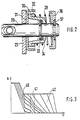
Eine Ausführung der Erfindung ist in der Zeichnung beschrieben und in der Figurenbeschreibung näher erläutert. Es zeigen: Figur 1 einen als Verstelldrehzahlregler ausgebildeten Drehzahlregler für eine als Verstelleinspritzpumpe ausgebildete Kraftstoffeinspritzpumpe in schematischer, unmaßstäblicher Darstellung; Figur 2 ein Drehzahl-Weg-Funktionsdiagramm des Verstell-Drehzahlreglers in Figur 1; und Figur 3 eine Einrichtung der Zusatzfeder in Axialschnitt und vergrößerter Darstellung.An embodiment of the invention is described in the drawing and explained in more detail in the description of the figures. FIG. 1 shows a speed controller designed as an adjusting speed controller for a fuel injection pump designed as an adjusting injection pump in a schematic, non-scale representation; FIG. 2 shows a speed-displacement function diagram of the variable speed controller in FIG. 1; and Figure 3 shows a device of the additional spring in axial section and enlarged view.
Bei einem Verstell-Drehzahlregler in Figur 1 wird ein Pumpenkolben 11 einer Kraftstoffeinspritzpumpe - die vorzugsweise für die Kraftstoffversorgung einer selbstzündenden Brennkraftmaschine für Kraftfahrzeuge verwendet wird - durch nicht dargestellte Mittel in eine hin- und hergehende, sowohl gleichzeitig rotierende Bewegung (Hub-Dreh-Bewegung) versetzt. Von einem nicht dargestellten, u. a. durch den Pumpenkolben 11 begrenzten Pumpenarbeitsraum führt ein im Pumpenkolben 11 verlaufender T-förmiger Entlastungskanal 12 zur Mantelfläche des Pumpenkolbens 11 und wird dort durch einen Ringschie ber 13 gesteuert. Bei der Hubbewegung des Pumpenkolbens 11 wird nach Zurücklegen eines bestimmten Hubes und je nach Position des Ringschiebers 13 der Entlastungskanal 12 früher oder später aufgesteuert und hierdurch die Einspritzung des Kraftstoffes unterbrochen; die axiale Lage des Ringschiebers 13 bestimmt somit die Einspritzmenge.In the case of an adjusting speed controller in FIG. 1, a
Der Ringschieber 13 wird durch einen Starthebel 14 verschoben, der um eine Achse 15 schwenkbar ist und mit einem Zapfen 16 in eine Nut 7 des Ringschiebers 13 für dessen Betätigung eingreift. Am anderen Ende des Starthebels 14 greift ein mittels der Motordrehzahl synchron angetriebener Drehzahlsignalgeber 18 an, der mittels Fliehgewichte 19 eine Verstellmuffe 20 verschiebt, die am Starthebel 14 kraftschlüssig anliegt. Dargestellt ist die Verteilereinspritzpumpe im Stillstand, bei welcher eine Leerlauf- und Startfeder 21 den Starthebel 14 in der dargestellten Ausgangslage gedrückt hält; in dieser nimmt der Regelschieber 3 eine Stellung für eine Startmehrmenge ein, die dem maximalen Nutzhub beim Start entspricht. Nach dem Starten des Motors schieben sich die Fliehgewichte 19 auseinander, so daß der Starthebel 14 um die Achse 15 so lange geschwenkt wird, bis dieser an einem Anschlag 22 eines Spannhebels 23 anschlägt und hierdurch die Startmehrmenge abgeregelt ist.The
Der Spannhebel 23 ist auf der Achse 15 schwenkbar gelagert und durch eine Regelfeder 25 belastet, die ihn in Anlage an einen Vollastanschlag hält. Mittels eines Verstellhebels 16 wird die Einstellung änderbar, die beim Abregeln des Drehzahlsignalgebers überwunden werden muß. Dabei entspricht die Stellung des Verstellhebels 26 dem jeweiligen - beispielsweise durch das Gaspedal des Fahrzeugs eingegebenen - Last in Verbindung mit dem gewünschten Drehzahl- bzw. dem Drehmomentwunsch des Fahrers der Brennkraftmaschine.The
Gleichwirkend zur Regelfeder 25 ist, wie in Figur 2 dargestellt, erfindungsgemäße eine Zusatzfeder 28 angeordnet. Der Verstellhebel 26 ist mit einer Öse der Regelfeder 25 verbunden. Die anderen Ösen der Regelfeder 25 ist mit einem Haltebolzen 29 verbunden. Der Haltebolzen geht durch eine Öffnung des Spannhebels 23 und hat an dem aus dem Spannhebel ragenden Teil zwei Ringnuten. In eine Nut ist ein Sicherungsring 33 eingebracht. Auf diesem Sicherungsring 33 liegt eine Ausgleichsscheibe 34 auf, und darauf ein "hutförmiger" axial verschiebbarer Federteller 30, dessen "Hutrand" Richtung Spannhebel geht und dort an einem weiteren tropfförmigen Federteller 31 anliegt, an dem seinerseits der Spannhebel 23 anliegt.An
Auf dem "hutförmigen" Rand des axial verschiebbaren Federtellers 30 liegt eine weitere Ausgleichsscheibe 32 auf, auf der die als Druckfeder ausgebildete Zusatzfeder 28 aufliegt. Die Zusatzfeder 28 wird zwischen einem weiteren am Ende des Haltebolzens 29 angeordneten ersten topfförmigen Federteller 36, der von einem in eine Ringnut eingesetzten Sicherungsring 37 gehalten wird, vorgespannt. Die axiale Festlegung der Federteller 30 und 36 erfolgt jeweils durch die Sicherungsringe 33 und 37 des Haltebolzens 29. Zwischen diesen beiden Federtellern 30, 36 ist die Zusatzfeder 28 vorgespannt, deren Vorspannung durch die Ausgleichsscheiben 32 und 34 verändert werden kann. Die Zusatzfeder 28 greift koaxial zur Regelfeder am Spannhebel 23 an und wirkt entgegengesetzt der Rückstellkraft des Drehzahlsignalgebers, d.h. die Zusatzfeder 28 wirkt gleichsinnig der Kraft der Regelfeder 25.On the "hat-shaped" edge of the axially
In Figur 3 ist ein Regelkennfeld des erfindungsgemäßen Drehzahlreglers dargestellt, in dem über der Absizze die Motordrehzahl n in Umdrehungen pro Minute und über der Ordinate der Weg s in Millimeter des Ringschiebers 13 aufgezeichnet ist. Das Verhalten des Verstellreglers wird bestimmt durch die Charakteristik der Leerlauffeder 21, der Regelfeder 25 und der Zusatzfeder 28. Derartige Größen beeinflussen den Leerlaufbetrieb. Gerade bei einem Leerlaufbetrieb, in dem verhältnismäßig niedere Leerlaufdrehzahlen eingehalten werden sollen, ist der Ungleichförmigkeitsgrad (P-Grad) der Einspritzmengenänderung über der Drehzahl niedrig, so daß sich einzelne, die Leerlaufdrehzahl beeinflussende Faktoren stark auswirken. Um sowohl einen optimalen P-Grad im Leerlauf zu realisieren, als auch den Fördermengenanstieg bei den Teillastkurven zu vermeiden, ist eine Regelung erforderlich, die nur in einem engen Drehzahlbereich arbeitet. Erfindungsgemäß kann durch die Wahl des Abstands der Sicherungsringe 33 und 37 der Weg des zweiten Federtellers 31 Richtung erster Federteller 36 eingestellt werden. Durch Verändern der Stärke der Ausgleichsscheiben 32 und 34 kann die Vorspannung der Zusatzfeder 28 eingestellt werden.FIG. 3 shows a control map of the speed controller according to the invention, in which the engine speed n in revolutions per minute is plotted on the abscissa and the path s in millimeters of the
Aus Figur 3 ist der Einfluß der Zusatzfeder 28 deutlich erkennbar. Der Regelschieber wird bei der Startmenge und bei bestimmter Drehzahl abgeregelt, danach folgt bei zunehmender Motordrehzahl ein Bereich 40, in dem die Leerlaufstartfeder wirksam ist, danach folgt der Leerlaufbereich 41 und ein Bereich 42, in dem die Regelfeder 25 wirksam ist. Die einzelnen Kurven zeigen den Abregelverlauf bei Zwischendrehzahlen. Im Bereich 41, dem Leerlaufbereich, in dem die Zusatzfeder wirksam ist, ist der P-Grad durch obige Maßnahmen und damit die Steigungsänderungen der einzelnen Abregelkurven so verändert, daß der P-Grad kleiner ist. Der P-Grad im Leerlauf ist stabil und es findet kein plötzlicher Fördermengenanstieg mehr statt.The influence of the
Claims (7)
die ein Drehzahlsignalgeber (18) erzeugt und mittels eines ein Einspritzmengenverstellglied der Pumpe verstellenden, und um eine Achse schwenkbaren zweiten Hebel (14) nach Anlage an einem Anschlag des Spannhebels (23) auf letzteren übertragbar ist
mit einer an einem der beiden Hebel angreifenden Leerlauffeder (21) und midestens einer zwischen den Hebeln angeordneten, als Druckfeder ausgebildeten Startfeder, die bis zur Anlage des zweiten Hebels (14) am Spannhebel (23) zusammendrückbar ist,
dadurch gekennzeichnet, daß
eine vorgespannte Zusatzfeder (28) in Reihe zur Regelfeder (25) geschaltet ist.1. Speed controller for fuel injection pumps with a pivoting lever (23) which can be pivoted about an axis and on which an adjustable control spring (25) acts against a restoring force,
which generates a speed signal transmitter (18) and can be transferred to the latter by means of a second lever (14) which adjusts an injection quantity adjusting element of the pump and which can be pivoted about an axis after abutment against a stop of the tensioning lever (23)
with an idle spring (21) acting on one of the two levers and at least one starting spring arranged between the levers and designed as a compression spring, which can be compressed until the second lever (14) rests on the tensioning lever (23),
characterized in that
a preloaded additional spring (28) is connected in series with the control spring (25).
Applications Claiming Priority (2)
| Application Number | Priority Date | Filing Date | Title |
|---|---|---|---|
| DE8708937U DE8708937U1 (en) | 1987-06-27 | 1987-06-27 | |
| DE8708937U | 1987-06-27 |
Publications (1)
| Publication Number | Publication Date |
|---|---|
| EP0297267A1 true EP0297267A1 (en) | 1989-01-04 |
Family
ID=6809514
Family Applications (1)
| Application Number | Title | Priority Date | Filing Date |
|---|---|---|---|
| EP88107922A Ceased EP0297267A1 (en) | 1987-06-27 | 1988-05-18 | Speed controlling device for fuel-injection pumps |
Country Status (3)
| Country | Link |
|---|---|
| EP (1) | EP0297267A1 (en) |
| JP (1) | JP2641504B2 (en) |
| DE (1) | DE8708937U1 (en) |
Cited By (2)
| Publication number | Priority date | Publication date | Assignee | Title |
|---|---|---|---|---|
| FR2710950A1 (en) * | 1993-10-04 | 1995-04-14 | Bosch Gmbh Robert | Cruise control for fuel injection pump of internal combustion engines. |
| GB2289549A (en) * | 1994-05-17 | 1995-11-22 | Kloeckner Humboldt Deutz Ag | Fuel injection device for an internal combustion engine |
Citations (4)
| Publication number | Priority date | Publication date | Assignee | Title |
|---|---|---|---|---|
| FR2345593A2 (en) * | 1973-07-17 | 1977-10-21 | Bosch Gmbh Robert | Speed regulator with idle run for fuel injector pumps - has pressure spring serving as compensator which must reach a stop before regulator spring is actuated |
| GB2090430A (en) * | 1980-12-31 | 1982-07-07 | Lucas Industries Ltd | Governor system |
| GB2119962A (en) * | 1982-05-01 | 1983-11-23 | Lucas Ind Plc | Governor mechanism for a fuel pumping apparatus |
| GB2152237A (en) * | 1983-12-23 | 1985-07-31 | Piaggio & C Spa | A centrifugal governor for an internal combustion engine |
Family Cites Families (2)
| Publication number | Priority date | Publication date | Assignee | Title |
|---|---|---|---|---|
| JPS5919102A (en) * | 1982-07-23 | 1984-01-31 | 株式会社マキタ電機製作所 | Motor tool also controlling at constant speed |
| JPS59123683A (en) * | 1982-12-28 | 1984-07-17 | Brother Ind Ltd | Thermal printer |
-
1987
- 1987-06-27 DE DE8708937U patent/DE8708937U1/de not_active Expired
-
1988
- 1988-05-18 EP EP88107922A patent/EP0297267A1/en not_active Ceased
- 1988-06-22 JP JP63152479A patent/JP2641504B2/en not_active Expired - Lifetime
Patent Citations (4)
| Publication number | Priority date | Publication date | Assignee | Title |
|---|---|---|---|---|
| FR2345593A2 (en) * | 1973-07-17 | 1977-10-21 | Bosch Gmbh Robert | Speed regulator with idle run for fuel injector pumps - has pressure spring serving as compensator which must reach a stop before regulator spring is actuated |
| GB2090430A (en) * | 1980-12-31 | 1982-07-07 | Lucas Industries Ltd | Governor system |
| GB2119962A (en) * | 1982-05-01 | 1983-11-23 | Lucas Ind Plc | Governor mechanism for a fuel pumping apparatus |
| GB2152237A (en) * | 1983-12-23 | 1985-07-31 | Piaggio & C Spa | A centrifugal governor for an internal combustion engine |
Non-Patent Citations (1)
| Title |
|---|
| PATENT ABSTRACTS OF JAPAN, Band 9, Nr. 168 (M-396)[1891], 13. Juli 1985; & JP-A-60 40 734 (NIPPON JIDOSHA BUHIN SOGO KENKYUSHO K.K.) 04-03-1985 * |
Cited By (3)
| Publication number | Priority date | Publication date | Assignee | Title |
|---|---|---|---|---|
| FR2710950A1 (en) * | 1993-10-04 | 1995-04-14 | Bosch Gmbh Robert | Cruise control for fuel injection pump of internal combustion engines. |
| GB2289549A (en) * | 1994-05-17 | 1995-11-22 | Kloeckner Humboldt Deutz Ag | Fuel injection device for an internal combustion engine |
| GB2289549B (en) * | 1994-05-17 | 1998-07-08 | Kloeckner Humboldt Deutz Ag | An injection device for an internal combustion engine |
Also Published As
| Publication number | Publication date |
|---|---|
| JP2641504B2 (en) | 1997-08-13 |
| JPS6432030A (en) | 1989-02-02 |
| DE8708937U1 (en) | 1988-10-27 |
Similar Documents
| Publication | Publication Date | Title |
|---|---|---|
| DE2900198A1 (en) | CENTRIFUGAL SPEED REGULATOR FOR INJECTION INTERNAL COMBUSTION ENGINES, IN PARTICULAR IDLE SPEED REGULATOR FOR VEHICLE DIESEL ENGINES | |
| EP0168613B1 (en) | Speed governor for a fuel injection pump | |
| EP0297267A1 (en) | Speed controlling device for fuel-injection pumps | |
| DE4129837C2 (en) | Speed controller for fuel injection pumps of internal combustion engines | |
| EP0166931B1 (en) | Speed governor for fuel injection pumps | |
| EP0515816B1 (en) | Fuel injection pump for internal combustion engines | |
| EP0162287A2 (en) | Fuel injection pump for internal combustion engines | |
| DE3630871C2 (en) | ||
| DE2612940A1 (en) | SPEED REGULATOR FOR A FUEL INJECTION PUMP | |
| EP0320617A2 (en) | Governor for fuel injection pumps | |
| EP0198166B1 (en) | Diaphragm-actuated pneumatic correcting device for a fuel injection pump of an internal-combustion engine | |
| EP0158846B1 (en) | Centrifugal governor for fuel injection-type internal-combustion engines | |
| EP0178441B1 (en) | Rotational speed governor for fuel injection pumps | |
| DE3201914A1 (en) | Fuel injection pump for internal combustion engines | |
| EP0344480A2 (en) | Fuel injection pump for internal-combustion engines, especially for diesel engines | |
| EP0624720B1 (en) | Fuel injection pump for internal combustion engines | |
| EP0208898B1 (en) | Speed governor for fuel injection pumps | |
| EP0296358B1 (en) | Device improving the dynamic behaviour of a governor of a distributor-type fuel injection pump | |
| EP0766782B1 (en) | Fuel injection pump for internal combustion engines | |
| DE3018720A1 (en) | Centrifugal governor for IC engine fuel injection pump - has idling spring acting against curved support for progressive stiffness | |
| DE3632538A1 (en) | FUEL INJECTION PUMP FOR INTERNAL COMBUSTION ENGINES | |
| EP0522359B1 (en) | Fuel injection pump for internal combustion engines | |
| DE3900317C2 (en) | Distributor fuel injection pump for internal combustion engines | |
| DE3336924C2 (en) | ||
| DE4332847A1 (en) | Fuel injection pump for IC engine - has actuator of return spring and coupling arrangement, to couple setting and adjusting levers |
Legal Events
| Date | Code | Title | Description |
|---|---|---|---|
| PUAI | Public reference made under article 153(3) epc to a published international application that has entered the european phase |
Free format text: ORIGINAL CODE: 0009012 |
|
| AK | Designated contracting states |
Kind code of ref document: A1 Designated state(s): DE FR GB |
|
| 17P | Request for examination filed |
Effective date: 19890603 |
|
| 17Q | First examination report despatched |
Effective date: 19900117 |
|
| STAA | Information on the status of an ep patent application or granted ep patent |
Free format text: STATUS: THE APPLICATION HAS BEEN REFUSED |
|
| 18R | Application refused |
Effective date: 19900819 |