EP0198166B1 - Diaphragm-actuated pneumatic correcting device for a fuel injection pump of an internal-combustion engine - Google Patents
Diaphragm-actuated pneumatic correcting device for a fuel injection pump of an internal-combustion engine Download PDFInfo
- Publication number
- EP0198166B1 EP0198166B1 EP86101703A EP86101703A EP0198166B1 EP 0198166 B1 EP0198166 B1 EP 0198166B1 EP 86101703 A EP86101703 A EP 86101703A EP 86101703 A EP86101703 A EP 86101703A EP 0198166 B1 EP0198166 B1 EP 0198166B1
- Authority
- EP
- European Patent Office
- Prior art keywords
- thrust rod
- stop
- spring
- end stop
- guide part
- Prior art date
- Legal status (The legal status is an assumption and is not a legal conclusion. Google has not performed a legal analysis and makes no representation as to the accuracy of the status listed.)
- Expired
Links
Images

Classifications
-
- F—MECHANICAL ENGINEERING; LIGHTING; HEATING; WEAPONS; BLASTING
- F02—COMBUSTION ENGINES; HOT-GAS OR COMBUSTION-PRODUCT ENGINE PLANTS
- F02D—CONTROLLING COMBUSTION ENGINES
- F02D1/00—Controlling fuel-injection pumps, e.g. of high pressure injection type
- F02D1/02—Controlling fuel-injection pumps, e.g. of high pressure injection type not restricted to adjustment of injection timing, e.g. varying amount of fuel delivered
- F02D1/06—Controlling fuel-injection pumps, e.g. of high pressure injection type not restricted to adjustment of injection timing, e.g. varying amount of fuel delivered by means dependent on pressure of engine working fluid
- F02D1/065—Controlling fuel-injection pumps, e.g. of high pressure injection type not restricted to adjustment of injection timing, e.g. varying amount of fuel delivered by means dependent on pressure of engine working fluid of intake of air
-
- F—MECHANICAL ENGINEERING; LIGHTING; HEATING; WEAPONS; BLASTING
- F02—COMBUSTION ENGINES; HOT-GAS OR COMBUSTION-PRODUCT ENGINE PLANTS
- F02B—INTERNAL-COMBUSTION PISTON ENGINES; COMBUSTION ENGINES IN GENERAL
- F02B3/00—Engines characterised by air compression and subsequent fuel addition
- F02B3/06—Engines characterised by air compression and subsequent fuel addition with compression ignition
Abstract
Description
Die Erfindung geht aus von einem pneumatischen Membranstellglied für eine Kraftstoffeinspritzeinrichtung von Brennkraftmaschinen, insbesondere von einem ladedruckabhängigen Vollastanschlag für aufgeladene Dieselmotoren nach dem gattungsbildenden Oberbegriff des Patentanspruchs 1.The invention relates to a pneumatic diaphragm actuator for a fuel injection device for internal combustion engines, in particular a boost pressure-dependent full-load stop for supercharged diesel engines according to the generic preamble of patent claim 1.
Ein solches pneumatisches Membranstellglied realisiert bei sogenannten Auflademotoren einen ladedruckabhängigen Vollastanschlag (LDA). Dieser LDA dient dazu, die bei Vollast geförderte Kraftstoffmenge im unteren Drehzahlbereich bei steigender Drehzahl von einem bestimmten Ladedruck an anzuheben. Dabei kann das Membranstellglied sowohl an die Kraftstoffeinspritzpumpe der Kraftstoffeinspritzeinrichtung angebaut sein und über ein Steuerglied auf ein Fördermengenverstellglied einwirken oder an einen Fliehkraft-Drehzahlregler der Kraftstoffeinspritzeinrichtung angeflanscht sein und über ein Steuerglied auf einen Regelhebel einwirken, der seinerseits das Fördermengenverstellglied steuert.Such a pneumatic diaphragm actuator realizes a boost pressure-dependent full-load stop (LDA) in so-called supercharging engines. This LDA is used to increase the fuel quantity delivered at full load in the lower speed range as the speed increases from a certain boost pressure. The diaphragm actuator can be attached to the fuel injection pump of the fuel injection device and act on a delivery rate adjustment member via a control member or flanged to a centrifugal speed controller of the fuel injection device and act via a control member on a control lever, which in turn controls the delivery rate adjustment member.
Aus der DE-A-31 37 145 ist ein Membranstellglied bekannt, das alle im Oberbegriff des Patentanspruchs 1 angegebenen Merkmale aufweist und durch die Verwendung zweier Rückstellfedern einen geknickten oder abgesetzten Fördermengenanstieg bei steigendem Ladedruck steuern kann, wenn allerdings die in die Ladeluftleitung eingesetzte Drosselvorrichtung entfernt oder bei steigendem Ladedruck ausgeschaltet ist. Durch den Einsatz der Drosselvorrichtung wird dem ladedruckabhängig gesteuerten Hub allerdings ein durch Betätigen des Verstellhebels ausgelöster Dämpfungshub vorgeschaltet, es werden dadurch aber auch zwei nacheinander gesteuerte Verschiebewege erzielt. Wenn nun beim bekannten Membranstellglied die Vorspannkraft der zweiten, als Druckfeder ausgebildeten und innerhalb einer auf der Schubstange montierten Federbaugruppe angeordneten Rückstellfeder korrigiert werden müßte, dann müßte nahezu der gesamte Anschlag auseinandergenommen werden, und die Vorspannkraft könnte nur in Stufen durch Beilegen von Scheiben an den Federenden eingestellt werden. Durch den danach erforderlichen, erneuten Zusammenbau besteht dann die Gefahr, daß andere, für andere Betriebskenngrößen verantwortliche Maße verstellt werden.From DE-A-31 37 145 a membrane actuator is known which has all the features specified in the preamble of claim 1 and can control a kinked or offset delivery rate increase with increasing boost pressure through the use of two return springs, but if the throttle device used in the charge air line is removed or is switched off when the boost pressure increases. Through the use of the throttle device, however, the stroke controlled as a function of boost pressure is preceded by a damping stroke triggered by actuating the adjusting lever, but it also achieves two successively controlled displacement paths. If the biasing force of the second return spring, designed as a compression spring and arranged within a spring assembly mounted on the push rod, had to be corrected in the known diaphragm actuator, then almost the entire stop would have to be taken apart, and the biasing force could only be increased in stages by the addition of disks at the spring ends can be set. The reassembly required afterwards then creates the risk that other dimensions which are responsible for other operating parameters are adjusted.
Ziel der Erfindung ist es deshalb, ein insbesondere als ladedruckabhängiger Vollastanschlag für aufgeladene Dieselmotoren arbeitendes pneumatisches Membranstellglied der gattungsgemä-Ben Bauart zu schaffen, bei dem die Einstellung und gegebenenfalls die Nachjustierung der einzelnen Betriebsparameter schnell und auf einfache Weise, mit der erforderlichen Präzision und unabhängig voneinander auch von ungeübten Fachkräften in wenigen Einstellschritten vorge-
- nommen werden kann.
- Vorteile der Erfindung
- can be taken.
- Advantages of the invention
Bei dem erfindungsgemäßen pneumatischen Membranstellglied mit den kennzeichnenden Merkmalen des Patentanspruchs 1 wird eine verbesserte Abstimmung des für die Kraftstoffmengensteuerung erforderlichen Regelweges, z. B. in Abhängigkeit vom Ladedruck, erzielt, bei dem zumindest die Vorspannkraft der für den weiteren Verschiebeweg verantwortlichen Druckfeder bereits außerhalb des Membranstellgliedes schnell und präzise eingestellt und gegebenenfalls bei toleranzbedingten Abweichungen der Druckverläufe auch noch am fertig montierten Membranstellglied nachgestellt werden kann, ohne daß wichtige Bauteile, des Membranstellgliedes entfernt werden müssen. Letzteres würde sonst wieder zu Abweichungen an anderen eingestellten Parametern führen. Durch die Verwendung der mindestens bezüglich der Vorspannkraft der Druckfeder stufenlos einstellbaren und außerhalb des Membranstellgliedes als voreingestellte Einheit vormontierten Federbaugruppe und die Anordnung des zweiten Endanschlages und der Federbaugruppe im Druckraum sind nur noch wenige, auch von ungeübten Fachkräften ausführbare Einstellschritte erforderlich, um eine vorgegebene gestufte Kennlinie einstellen zu können. Eine eventuell noch erforderliche Nachstellung der Federvorspannkraft kann dann auch ohne Veränderung anderer Einstellgrößen auf einfache Weise vorgenommen werden. Es können demnach sowohl die Stellung der Schubstange beim ersten als auch beim zweiten, demgegenüber höheren Mindestdruck sowie der Gesamtweg der Schubstangenverschiebung getrennt voneinander und ohne gegenseitige Beeinflussung sehr einfach eingestellt werden, wodurch z. B. ein über einen großen Drehzahlbereich konstantes Drehmoment an der Brennkraftmaschine gesteuert werden kann.In the pneumatic membrane actuator according to the invention with the characterizing features of claim 1, an improved coordination of the control path required for the fuel quantity control, for. B. as a function of the boost pressure, achieved at which at least the biasing force of the compression spring responsible for the further displacement already outside of the diaphragm actuator is quickly and precisely adjusted and, if necessary, can also be readjusted on the fully assembled diaphragm actuator in the event of tolerance-related deviations in the pressure curves, without important components , the diaphragm actuator must be removed. The latter would otherwise lead to deviations in other set parameters. Due to the use of the spring assembly, which is infinitely adjustable at least with regard to the preload force of the compression spring and preassembled outside the diaphragm actuator as a preset unit, and the arrangement of the second end stop and the spring assembly in the pressure chamber, only a few adjustment steps can be carried out, even by inexperienced specialists, in order to achieve a predetermined, stepped characteristic curve to be able to adjust. Any adjustment of the spring preload that may still be required can then be carried out in a simple manner even without changing other setting variables. It can therefore both the position of the push rod at the first and the second, in contrast higher minimum pressure and the total path of the push rod displacement separately from each other and without mutual interference can be set very easily, whereby z. B. can be controlled over a large speed range constant torque on the internal combustion engine.
Durch die in den Unteransprüchen aufgeführten Maßnahmen sind vorteilhafte Weiterbildungen und Verbesserungen des im Patentanspruch 1 angegebenen Membranstellglieds möglich. So wird gemäß den in den Ansprüchen 2 bis 6 angegebenen Ausführungsformen der Erfindung eine fertigungstechnisch einfache Herstellung und zeitsparende Montage, eine schnelle Justierung und eine einfache Nachjustierung des Membranstellglieds während des Betriebs der Brennkraftmaschine ermöglicht.The measures listed in the subclaims allow advantageous developments and improvements of the diaphragm actuator specified in claim 1. Thus, according to the embodiments of the invention specified in claims 2 to 6, simple manufacturing and time-saving assembly, rapid adjustment and simple readjustment of the membrane actuator is made possible during operation of the internal combustion engine.
In einer vorteilhaften Weiterbildung des Erfindungsgegenstandes wird gemäß den kennzeichnenden Merkmalen des Anspruchs 7 die Federbaugruppe in ein Innengewinde in der Wand der Druckkammer eingeschraubt und legt mit ihrer Einbaulage den weiteren Verschiebeweg der Schubstange fest. Diese Ausführungsvariante ist vor allem dann vorteilhaft, wenn wegen geringer Stellkräfte die an der Schubstange befestigte Masse möglichst klein sein soll, um ungewollte Stellbewegungen aufgrund der am Dieselmotor auftretenden Beschleunigungskräfte auszuschlie-Ben. Ist die Federbaugruppe gemäß den kennzeichnenden Merkmalen des Anspruchs 8 aufgebaut, dann kann diese Federbaugruppe entweder als voreingestellte Federkapsel für eine einfache Montage und Nachjustierung eingebaut werden, oder sie kann für einen voll einstellbaren Ladedruckanschlag verwendet werden. Bei diesem sind dann sowohl die Verschiebewege der Schubstange für die beiden Verstellstufen als auch die Vorspannkräfte der Rückstellfeder und der Druckfeder getrennt voneinander und bei richtiger Einstellfolge auch unabhängig voneinander ein- und nachstellbar.In an advantageous development of the subject matter of the invention, the spring assembly is screwed into an internal thread in the wall of the pressure chamber and, with its installed position, defines the further displacement path of the push rod. This variant is particularly advantageous if it is less Actuating forces the mass attached to the push rod should be as small as possible in order to prevent unwanted actuating movements due to the acceleration forces occurring on the diesel engine. If the spring assembly is constructed in accordance with the characterizing features of claim 8, then this spring assembly can either be installed as a preset spring capsule for easy assembly and readjustment, or it can be used for a fully adjustable boost pressure stop. In this case, both the displacement of the push rod for the two adjustment stages and the pretensioning forces of the return spring and the compression spring can then be adjusted and adjusted independently of one another and, with the correct setting sequence, independently of one another.
Durch die in Anspruch 9 festgelegten Merkmale ist eine bezüglich des benötigten Einbauraums gedrängte Bauweise des Membranstellglieds erreichbar.The features defined in claim 9 make it possible to achieve a compact construction of the diaphragm actuator with respect to the required installation space.
Das Teilmerkmal der stirnseitig mit dem den weiteren Verschiebeweg der Schubstange festlegenden Abstand von dem zweiten Endanschlag im Stellgliedgehäuse befestigten Federbaugruppe aus Anspruch 7 ist für sich gesehen aus der JP-A-55-96 328 (siehe besonders Figuren 5, 7 oder 8) bekannt, eine voneinander unabhängige Einstellung der einzelnen Betriebsparameter ist dort jedoch nicht und auch nicht ohne Ausbau wichtiger Bauteile möglich.The partial feature of the spring assembly fastened on the end face with the distance from the second end stop in the actuator housing which defines the further displacement path of the push rod is known per se from JP-A-55-96 328 (see in particular FIGS. 5, 7 or 8), independent adjustment of the individual operating parameters is not possible there, however, and also not possible without removing important components.
Die Erfindung ist anhand zweier in der Zeichnung dargestellter Ausführungsbeispiele in der nachfolgenden Beschreibung näher erläutert. Es zeigen :
- Fig. 1 einen Längsschnitt durch das erste Ausführungsbeispiel eines erfindungsgemäßen pneumatischen Membranstellglieds eines ladedruckabhängigen Vollastanschlags für eine Kraftstoffeinspritzeinrichtung von Brennkraftmaschinen,
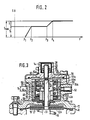
- Fig. 2 ein Diagramm des Verschiebewegs einer Schubstange in Abhängigkeit von dem Ladedruck in einem Druckraum des Membranstellglieds in Fig. 1
- Fig. 3 einen Teillängsschnitt entsprechend Figur 1, jedoch durch das zweite Ausführungsbeispiel.
- 1 shows a longitudinal section through the first exemplary embodiment of a pneumatic diaphragm actuator according to the invention of a boost pressure-dependent full-load stop for a fuel injection device of internal combustion engines,
- FIG. 2 shows a diagram of the displacement path of a push rod as a function of the boost pressure in a pressure chamber of the membrane actuator in FIG. 1
- Fig. 3 shows a partial longitudinal section corresponding to Figure 1, but by the second embodiment.
Das in Figur 1 als bevorzugtes, erstes Ausführungsbeispiel dargestellte und zum Anbau an eine Kraftstoffeinspritzpumpe oder einen Fliehkraft-Drehzahlregler einer Kraftstoffeinspritzeinrichtung geeignete pneumatische Membranstellglied ist ein Stellglied eines ladedruckabhängigen Vollastanschlages und weist ein zweiteiliges Gehäuse 10 mit einem ersten und zweiten Gehäuseteil 11, 12 auf, die unter Einspannen einer Mem- . bran 13 miteinander verschraubt sind. Der zweite Gehäuseteil 12 ist stirnseitig mit einem Gehäusedeckel 14 abgedeckt, der zusammen mit der Membran 13 einen Druckraum 15 im zweiten Gehäuseteil 12 begrenzt, dem über eine Anschlußbohrung 16 der in der Ansaugleitung des Motors herrschende Ladeluftdruck zugeführt wird.The pneumatic diaphragm actuator shown in FIG. 1 as a preferred, first exemplary embodiment and suitable for attachment to a fuel injection pump or a centrifugal speed governor of a fuel injection device is an actuator of a boost-pressure-dependent full-load stop and has a two-
Im ersten Gehäuseteil 11 ist eine Schubstange 17 in einer Lagerhülse 18 axial verschieblich geführt, die in den Boden des ersten Gehäuseteils 11 eingeschraubt ist und ein verstellbares Widerlager für eine die Schubstange 17 koaxial umgebende Rückstellfeder 19 bildet, die sich an der Membran 13 unter Zwischenlage einer Verbindungsplatte 20 abstützt. Die Schubstange 17 wirkt mit ihrem aus dem Gehäuse 10 herausragenden Ende über ein angelenktes Steuerglied 21 mit einer nicht dargestellten Regelstange in der Kraftstoffeinspritzeinrichtung zusammen.In the
Die Schubstange 17 ragt mit einem im Durchmesser reduzierten Schubstangenabschnitt 17a durch die Membran 13 hindurch bis in den Druckraum 15 im zweiten Gehäuseteil 12 und ist mit der Membran 13 dadurch verbunden, daß auf der der Verbindungsplatte 20 gegenüberliegenden Seite der Membran 13 eine weitere Verbindungsplatte 22 auf den Schubstangenabschnitt 17a aufgeschoben und durch eine auf einem Außengewinde 23 des Schubstangenabschnitts 17a verschraubbare Spannmutter 24 gegen eine Ringschulter 25 an dem den größeren Durchmesser aufweisenden Schubstangenabschnitt 17b angepreßt ist.The
Die Schubstange 17 ist mittels der Membran 13 bei Druckbeaufschlagung des Druckraums 15 entgegen der Kraft der Rückstellfeder 19 zwischen zwei gehäusefesten Endanschlägen 26, 27 axial verschiebbar. Beide Endanschläge 26, 27 sind im Druckraum 15 angeordnet. Der erste Endanschlag 26 wird von einer Anschlagschraube 28 gebildet, die im Gehäusedeckel 14 verschraubbar ist und mit der Schubstange 17 fluchtet. In der gewählten Anschlagstellung wird die Anschlagschraube 28 mittels einer Kontermutter 29 am Gehäusedeckel 14 fixiert. An dieser Anschlagschraube 28 liegt in der gezeichneten drucklosen Ausgangsstellung der Schubstange 17 die Stirnseite des Schubstangenabschnitts 17a an. Die Anschlagschraube 28 dient zur Festlegung der Ausgangsstellung der Schubstange 17 bei drucklosem Druckraum 15 und damit der Festlegung der Saugmenge. Der zweite Endanschlag 27 ist an einem im axialen Abstand von dem Gehäusedeckel 14 ins Innere des Druckraums 15 vorspringenden ringförmigen Radialsteg 30 angeordnet, und zwar in Form einer Ringscheibe 31 aus gehärtetem Federstahl. Die gehäusefeste Ringscheibe 31 wirkt mit einem auf der Schubstange 17, und zwar auf dem Schubstangenabschnitt 17a, verstellbar befestigten Gegenanschlag 32 zusammen. Der Gegenanschlag 32 bestimmt die Stellung der Schubstange 17 bei vollem Ladedruck und legt damit die Vollastmenge bei vollem Ladedruck, die sog. Ladermenge, fest.The
Der Gegenanschlag 32 ist als Teil einer vorgespannten Federbaugruppe 33 mit zwei Anschlagstellungen derart ausgebildet, daß mit Erreichen der ersten Anschlagstellung an der Ringscheibe 31 nach Zurücklegung des Schubstangen-Verschiebeweges S1 nach Überwinden der Federvorspannung der Federbaugruppe 33 ein weiterer Verschiebeweg S2 der Schubstange 17 bis zum Erreichen der zweiten Anschlagstellung an der Ringscheibe 31 zur Verfügung steht. Im weiteren Verschiebeweg S2 addieren sich dabei die Federkraft der Federbaugruppe 33 und die Federkraft der Rückstellfeder 19.The
Die Federbaugruppe 33 weist hierzu ein zylindrisches Führungsteil 34 mit einer axialen Stufenbohrung 35 auf. Der Bohrungsabschnitt 35a mit dem kleineren Durchmesser trägt ein Innengewinde 36, mit welchem das Führungsteil 34 auf dem Außengewinde 23 des Schubstangenabschnitts 17a verschraubt ist. Das Führungsteil 34 wird durch eine Feststellmutter 38, die im Innern des den größeren Durchmesser aufweisenden Bohrungsabschnittes 35b auf dem Außengewinde 23 des Schubstangenabschnitts 17a verschraubbar ist, gekontert, wobei sich die Feststellmutter 38 an die zwischen den Bohrungsabschnitten 35a und 35b befindliche Übergangsschulter 35c anpreßt. An der der Ringscheibe 31 zugekehrten Stirnseite trägt das Führungsteil 34 einen radialen nach außen abstehenden Ringflansch 39, dessen von der Ringscheibe 31 abgekehrte Ringfläche eine Mitnahmeschulter 40 für ein Federabstützteil 41, das auf einer äußeren Führungsfläche 42 des Führungsteils 34 axial verschieblich gehalten ist, bildet.For this purpose, the
Das hohlzylindrisch ausgebildete Federabstützteil 41 liegt mit seiner Innenzylinderwand auf der äußeren Führungsfläche 42 des Führungsteils 34 auf und trägt in seiner der Ringscheibe 31 zugekehrten Stirnseite eine konzentrische Ausnehmung 43, deren Durchmesser größer ist als der Außendurchmesser des Ringflansches 39 des Führungsteils 34. Die Tiefe der Ausnehmung 43 ist größer bemessen als die Summe aus der axialen Dicke des Ringflansches 39 und dem gewünschten Verschiebeweg S2 des Führungsteils 34 bzw. der Schubstange 17 nach Erreichen der ersten Anschlagstellung der Federbaugruppe 33.The hollow cylindrical
Zur exakten Einstellung des Verschiebewegs S2 ist zwischen der Mitnahmeschulter 40 am Ringflansch 39 und einer Bodenringfläche 44 der Ausnehmung 43 eine Distanzscheibe 45 eingelegt. Das Federabstützteil 41 wird durch eine das Federabstützteil 41 und das Führungsteil 34 koaxial umgebende Druckfeder 46 mit der Bodenringfläche 44 der Ausnehmung 43 gegen die Distanzscheibe 45 und diese gegen die Mitnahmeschulter 40 des Ringflansches 39 am Führungsteil 34 gepreßt. Hierzu stützt sich die Druckfeder 46 an einer ringförmigen Stützschulter 47 am Federabstützteil 41 und an einem Einstellring 48 ab, der auf einem Außengewindeabschnitt 49 des. Führungsteils 34 verschraubbar ist. Durch mehr oder weniger weites Aufschrauben des Einstellringes 48 auf das Führungsteil 34 kann die Vorspannung der Druckfeder 46 eingestellt werden. Die stirnseitige Ausbildung des Federabstützteils 41 ist so getroffen, daß die stirnseitig verbleibende Ringfläche und der Außendurchmesser des Federabstützteils 41 mit Ringbreite und Außendurchmesser der zur Schubstange 17 konzentrisch angeordneten Ringscheibe 31, die den zweiten Endanschlag 27 bildet, korrespondieren. Die Federbaugruppe 33 wird in der Weise vormontiert daß zunächst das Federabstützteil 41 auf das Führungsteil 34 aufgeschoben wird und der Ver- schiebeweg S2 mittels der Distanzscheibe 45 festgelegt wird. Dann wird die Druckfeder 46 aufgesetzt und die Vorspannung der Druckfeder 46 mittels des Einstellringes 48 festgelegt. Danach wird die so vormontierte und fertig eingestellte Federbaugruppe 33 mit dem Führungsteil 34 auf das Außengewinde 23 des Schubstangenabschnitts 17a so weit aufgeschraubt, daß der Verschiebeweg S1 festgelegt ist, und durch die Feststellmutter 38 gekontert.For exact adjustment of the displacement S 2 , a
Zur Einstellung des Membranstellgliedes wird nunmehr mit der Anschlagschraube 28 die Grundstellung der Schubstange 17 'bei drucklosem Druckraum 15 eingestellt. Mittels der Kontermutter 29 wird diese Stellung der Anschlagschraube 28 fixiert. Danach wird der Verstellbeginn der Verschiebebewegung der Schubstange 17, also der zur Anfangsverschiebung der Schubstange 17 erforderliche Mindestladedruck p1, durch Verdrehen der Lagerhülse 18 und die damit verbundene. Einstellung der Vorspannung der Rückstellfeder 19 eingestellt. Anschließend wird, falls notwendig, durch Verdrehen des Einstellringes 48 die Vorspannung der Druckfeder 46 in der Federbaugruppe 33 derart korrigiert, daß der abermalige Verstellbeginn der Schubstange 17 nach Durchlaufen des ersten Verschiebeweges S1 bei Erreichen des gewünschten zweiten Mindestladedruckes p3 einsetzt.To adjust the diaphragm actuator, the basic position of the
Durch diese Justierung des Membranstellgliedes weist dessen Schubstange 17 eine vom Ladedruck p im Druckraum 15 abhängige Verschiebeweg-Kennlinie auf, wie sie in Fig. 2 dargestellt ist. Wie daraus ohne weiteres ersichtlich ist, setzt nach Überwindung der Vorspannkraft der Rückstellfeder 19 beim Ladedruck P1 eine erste Verschiebebewegung der Schubstange 17 ein, die proportional der Druckzunahme des Ladedrucks von P1 nach p2 ist. Hat die Schubstange 17 den Verschiebeweg S1 zurückgelegt, so schlägt das stirnseitig axial über das Führungsteil 34 vorstehende Federabstützteil 41 an der den zweiten Endanschlag 27 bildenden Ringscheibe 31 an. Die Schubstange 17 kann nunmehr nur noch durch Mitnahme des Führungsteils 34 relativ zu dem blockierten Federabstützteil 41 verschoben werden. Dieser Verschiebung entgegengerichtet wirkt die Druckfeder 46. Ist der Ladedruck im Druckraum 15 bis auf den Wert p3 angestiegen, so ist die Vorspannkraft der Druckfeder 46 überwunden, so daß nunmehr die zweite Verschiebebewegung der Schubstange 17 über den Verschiebeweg S2 einsetzt. Bei Erreichen des auch als Vorgabedruck bezeichneten erhöhten Ladedrucks p4 stößt die Stirnseite des Führungsteils 34 an der Ringscheibe 31 an, und die Schubstange 17 hat ihre Endstellung erreicht und den maximalen, sich aus der Summe der Verschiebewege S1 und S2 zusammensetzenden Verschiebe- weg Smax durchlaufen.As a result of this adjustment of the diaphragm actuator, its
Die Erfindung ist nicht auf das vorstehend beschriebene erste Ausführungsbeispiel beschränkt. So brauchen die beiden gegeneinander verspannten koaxialen Bauteile der Federbaugruppe 33, die in dem ersten Ausführungsbeispiel von dem Führungsteil 34 und dem Federabstützteil 41 gebildet werden, nicht auf der Schubstange zu sitzen, sondern sie sind bei dem nachstehend beschriebenen zweiten Ausführungsbeispiel im zweiten Gehäuseteil 12 koaxial zu der Schubstange 17 gehalten.The invention is not restricted to the first exemplary embodiment described above. Thus, the two mutually braced coaxial components of the
Das in Figur 3 dargestellte zweite Ausführungsbeispiel unterscheidet sich von dem zu Figur 1 beschriebenen ersten Ausführungsbeispiel, wie im vorhergehenden Abschnitt bereits angedeutet, im wesentlichen durch die geänderte Ausführungsform der Federbaugruppe 33A, Gleiche Teile werden dabei gleich bezeichnet, abweichende Teile mit dem Großbuchstaben A versehen und neue Teile neu bezeichnet.The second exemplary embodiment shown in FIG. 3 differs from the first exemplary embodiment described in relation to FIG. 1, as already indicated in the previous section, essentially by the modified embodiment of the spring assembly 33A, the same parts are given the same name, different parts are provided with the capital letter A and redesignated new parts.
Die Federbaugruppe 33A ist in ein Innengewinde 51 in der Wand der Druckkammer 15 eingeschraubt, bildet stirnseitig den Gegenanschlag 32A, weist einen den weiteren Verschiebeweg S2 der Schubstange 17 festlegenden Abstand von dem zweiten Endanschlag 27 auf und ist in dieser Einbaulage durch eine Sicherungsschraube 52 lagegesichert im zweiten Gehäuseteil 12 des Stellgliedgehäuses 10 und koaxial zur Schubstange 17 befestigt. Das eine der beiden relativ zueinander verschieblich angeordneten und mittels der Druckfeder 46 gegeneinander verspannten Bauteile der Federbaugruppe 33A ist von einer Gewindehülse 53 mit einer in ein Innengewinde 54 dieser Hülse eingeschraubten Einstellhülse 55 gebildet, und das zweite Bauteil ist ein zwischen Schubstange 17 und Gewindehülse 53 mit Einstellhülse 55 axial verschieblich und koaxial zu diesen Teilen angeordnetes Federabstützteil 41A. Die Druckfeder 46 stützt sich einerseits an einer Stützschulter 56 innerhalb der Gewindehülse 53 und andererseits an einem radial vom Federabstützteil 41A abstehenden Ringflansch 58 ab. Dabei wird der Ringflansch 58 in der gezeichneten Lage seinerseits von der Druckfeder 46 in Anlage an eine Innenschulter 55a der Einstellhülse 55 gedrückt, und die Stützschulter 56 ist von einer der Druckfeder 46 zugewandten Stirnfläche einer Ringscheibe 59 gebildet, welche ihrerseits an einem in eine nicht näher bezeichnete Ringnut eingesetzten Innensprengring 60 anliegt.The spring assembly 33A is screwed into an internal thread 51 in the wall of the
Von einer zu dem von der Anschlagschraube 28 gebildeten ersten Endanschlag 26 hin offenen Ausnehmung 61 innerhalb des Federabstützteils 41A ist eine Anschlagschulter 61a gebildet, und die Schubstange 17 trägt auf ihrem mit Gewinde versehenen Schubstangenabschnitt 17a im Bereich zwischen dem ersten Endanschlag 26 und der Anschlagschulter 61a eine durch eine Kontermutter 62 in der dargestellten Einbaulage gesicherte Stellmutter 63. In der gezeichneten Ruhelage der Schubstange 17 liegt diese am ersten Endanschlag 26 an, und die Stellmutter 63 ist so eingestellt, daß zwischen der Anschlagschulter 61a im Federabstützteil 41A und einer Anschlagfläche 63a an der Stellmutter 63 ein den ersten Verschiebeweg S, festlegender Abstand vorhanden ist. Wie Figur 3 zeigt, befindet sich die Anschlagfläche 63a an einen Absatz zwischen einem im Durchmesser reduzierten, nicht näher bezeichneten Abschnitt und einem Ringbund 64 dieser Stellmutter 63. Der Ringbund 64 trägt an seinem Umfang Ausnehmungen, die den Eingriff eines Verstellwerkzeugs ermöglichen, und die Kontermutter 62 hat entsprechende stirnseitige Ausnehmungen 62a, so daß beide Muttern 62, 63 durch ein doppelwandiges Rohrwerkzeug verstellt und gekontert werden können. Auch die Gewindehülse 53 ist stirnseitig mit Quernuten 53a versehen, die dem Eingriff eines Werkzeugs dienen, und die Einstellhülse 55 weist ein Innensechskant 55b oder einen ähnlich geformten Durchbruch für den Eingriff eines entsprechenden Werkzeugs auf. Damit können alle wichtigen Betriebskennwerte bei Einhaltung der vorgeschriebenen Einstellfolge stufenlos und unabhängig voneinander eingestellt und gegebenenfalls auch nachjustiert werden. Bei diesem zweiten Ausführungsbeispiel wird eine gleiche Verschiebeweg-Kennlinie wie beim ersten Ausführungsbeispiel nach Figur 1 erzielt, so daß das Diagramm in Figur 2 auch für dieses Ausführungsbeispiel gilt.A
Die Einstellung des in Figur 3 dargestellten zweiten Ausführungsbeispiels des Membranstellgliedes weicht in einigen Arbeitsschritten von der des ersten Ausführungsbeispiels nach Figur 1 ab. Die-Einstellung der gezeichneten Grundstellung der Schubstange 17 bei drucklosem Saugraum 15 mittels der durch die Kontermutter 29 gesicherten Anschlagschraube 28 und die Einstellung der Vorspannung der Rückstellfeder 19 für die beim Mindestladedruck pl beginnende Anfangsverschiebung der Schubstange 17 geschehen auf gleiche Weise wie beim ersten Ausführungsbeispiel.The setting of the second exemplary embodiment of the diaphragm actuator shown in FIG. 3 deviates in some work steps from that of the first exemplary embodiment according to FIG. 1. The setting of the drawn basic position of the
Nach dem Einstellen der Grundstellung der Schubstange 17 für den Anfangspunkt bei p, auf der Verschiebeweg-Kennlinie in Figur 2 wird der Gehäusedeckel 14 abgenommen, und die Federbaugruppe 41A und die Stellmutter 63 werden in ihre gezeichnete Lage gebracht, in der die Verschiebewege S, und S2 gesteuert werden. Dazu wird zuerst die Federbaugruppe 33A soweit eingeschraubt, bis das Federabstützteil 41A stirnseitig am zweiten Endanschlag 27 anliegt. Danach wird die Schubstange in eine Stellung für den maximalen Verschiebeweg Smax verstellt, der sich aus der Summe der beiden Verschiebewege S, und S2 zusammensetzt. In dieser Stellung wird die Schubstange 17 fixiert. und die Stellmutter 63 wird bis zur Anlage ihrer Anschlagfläche 63a an der Anschlagschulter 61a eingeschraubt und in dieser Lage durch die Kontermutter 62 gesichert. Danach wird die Schubstange 17 um den Verschiebeweg S2 in Richtung auf den Anschlag 26 hin zurückverstellt und die Gewindehülse 53 wird um den gleichen Betrag zurückverstellt, so daß die Anschlagschulter 61 wieder an der Anschlagfläche 63a anliegt. Das Federabstützteil 41A steht jetzt in der gezeichneten, den Verschiebeweg S2 festlegenden Einbaulage. War die Federvorspannung der Druckfeder 46 durch Einstellen der Einstellhülse 55 bereits vor dem Einbau voreingestellt, so ist bereits jetzt die gesamte Einstellung beendet. Bei wiederaufgesetztem Gehäusedeckel 14 schlägt dann die Schubstange 17 an dem ersten Endanschlag 26 an und die Anschlagschulter 61a nimmt dann den den Verschiebeweg S1 festlegenden Abstand zur Anschlagfläche 63a ein.After setting the basic position of the
Ist trotz voreingestellter oder bei nicht eingestellter Federbaugruppe 33A eine Einstellung oder Korrektur der Federvorspannkraft der Druckfeder 46 erforderlich, so hat diese nach dem Einstellen des Verschiebeweges S2 zu erfolgen, indem die Einstellhülse 55 durch ein in das Innensechskant 55b eingefügtes Werkzeug festgehalten und nur die Gewindehülse 53 verstellt wird. Damit sich dabei die Einbaulage der Einstellhülse 55 und des Federabstützteiles 41A nicht verändert, haben die Innengewinde 51 und 54 eine gleiche Steigung.If an adjustment or correction of the spring pretensioning force of the
Bei diesem zweiten Ausführungsbeispiel können also sowohl die Verschiebewege S1 und S2 als auch die Meßunkte für den jeweiligen Verstellbeginn bei den Ladedrücken p1 und p3 stufenlos ein- und nachgestellt werden.In this second exemplary embodiment, both the displacement paths S 1 and S 2 and the measuring points for the respective start of adjustment at the charging pressures p 1 and p 3 can be infinitely adjusted and adjusted.
Auch hier stehen somit - wie bei dem ersten Ausführungsbeispiel - die zu der voreingestellten Federbaugruppe 33A miteinander verspannten Bauteile, das sind die Gewindehülse 53 mit Einstellhülse 55 und das Federabstützteil 41A, einerseits mit der Schubstange 17 und andererseits mit dem zweiten Endanschlag 27 in einer solchen Wirkverbindung, daß nach Zurücklegen des ersten Verschiebeweges S1 entgegen der Rückstellkraft der Rückstellfeder 19 eine erste Anschlagstellung erreicht wird und dann nach Überwinden der Vorspannkraft der Druckfeder 46 durch Relatiwerschiebung dieser Bauteile entgegen der Federkraft der Druckfeder 46 der weitere Verschiebeweg e2 der Schubstange 17 bis zur zweiten Anschlagstellung am zweiten Endanschlag 27 zur Verfügung steht. Im weiteren Verschiebeweg S2 ist damit die Schubstangen-Rückstellkraft um die Federkraft der Druckfeder 46 erhöht, und es ergibt sich, wie beim ersten Ausführungsbeispiel, der in Figur 2 eingezeichnete flachere Verlauf der Verschiebeweg-Kennlinie zwischen den Ladedrücken P3 und p4 gegenüber dem steileren Verlauf zwischen p1 und p2.Here too, as in the first exemplary embodiment, the components clamped together to form the preset spring assembly 33A, that is, the threaded
Claims (9)
Priority Applications (1)
| Application Number | Priority Date | Filing Date | Title |
|---|---|---|---|
| AT86101703T ATE43153T1 (en) | 1985-03-09 | 1986-02-11 | DIAPHRAGM PNEUMATIC ACTUATOR FOR AN ENGINE FUEL INJECTION DEVICE. |
Applications Claiming Priority (4)
| Application Number | Priority Date | Filing Date | Title |
|---|---|---|---|
| DE3508519 | 1985-03-09 | ||
| DE3508519 | 1985-03-09 | ||
| DE3543334 | 1985-12-07 | ||
| DE19853543334 DE3543334A1 (en) | 1985-03-09 | 1985-12-07 | PNEUMATIC DIAPHRAGM ACTUATOR FOR A FUEL INJECTION DEVICE OF INTERNAL COMBUSTION ENGINES |
Publications (3)
| Publication Number | Publication Date |
|---|---|
| EP0198166A2 EP0198166A2 (en) | 1986-10-22 |
| EP0198166A3 EP0198166A3 (en) | 1986-10-29 |
| EP0198166B1 true EP0198166B1 (en) | 1989-05-17 |
Family
ID=25830171
Family Applications (1)
| Application Number | Title | Priority Date | Filing Date |
|---|---|---|---|
| EP86101703A Expired EP0198166B1 (en) | 1985-03-09 | 1986-02-11 | Diaphragm-actuated pneumatic correcting device for a fuel injection pump of an internal-combustion engine |
Country Status (7)
| Country | Link |
|---|---|
| US (1) | US4727839A (en) |
| EP (1) | EP0198166B1 (en) |
| JP (1) | JP2557839B2 (en) |
| AT (1) | ATE43153T1 (en) |
| BR (1) | BR8601000A (en) |
| DE (2) | DE3543334A1 (en) |
| ES (1) | ES8706229A1 (en) |
Families Citing this family (4)
| Publication number | Priority date | Publication date | Assignee | Title |
|---|---|---|---|---|
| US5101793A (en) * | 1990-10-30 | 1992-04-07 | Sample Larry A | Manually adjustable override for fuel injection regulators |
| US5218940A (en) * | 1991-03-22 | 1993-06-15 | Navistar International Transportation Corp. | Aneroid boost modulator |
| DE4241997C1 (en) * | 1992-12-12 | 1994-05-26 | Daimler Benz Ag | Pneumatic actuator drive - has roll membrane to execute normal stroke af actuator into working position |
| US7721718B2 (en) | 2007-02-08 | 2010-05-25 | Perkins Engines Company Limited | System for controlling an air to fuel ratio |
Family Cites Families (16)
| Publication number | Priority date | Publication date | Assignee | Title |
|---|---|---|---|---|
| US2569664A (en) * | 1947-11-05 | 1951-10-02 | American Bosch Corp | Combined mechanical and pneumatic governor |
| US2893366A (en) * | 1955-10-31 | 1959-07-07 | Bosch Arma Corp | Fuel injection apparatus |
| GB883502A (en) * | 1958-10-04 | 1961-11-29 | Lavalette Ateliers Constr | A pneumatic fuel-delivery regulator for use in internal-combustion engines |
| US3149619A (en) * | 1960-12-19 | 1964-09-22 | Borg Warner | Fuel injection idle enrichment control mechanism |
| GB1371762A (en) * | 1971-03-02 | 1974-10-23 | Lucas Industries Ltd | Control apparatus for an internal combustion engine fuel injection system |
| US3795233A (en) * | 1972-05-19 | 1974-03-05 | Caterpillar Tractor Co | Fuel-air ratio control for supercharged engines |
| DE2537710A1 (en) * | 1975-08-23 | 1977-03-03 | Daimler Benz Ag | A PNEUMATIC SPEED CONTROLLER CONNECTED TO THE INJECTION PUMP OF A COMPRESSING INJECTION COMBUSTION MACHINE |
| DE2540986A1 (en) * | 1975-09-13 | 1977-03-17 | Daimler Benz Ag | ARRANGEMENT FOR REGULATING THE INJECTION QUANTITY OF AN INJECTION COMBUSTION ENGINE |
| DE2731107A1 (en) * | 1977-07-09 | 1979-01-25 | Bosch Gmbh Robert | CONTROL DEVICE FOR CHARGED INJECTION COMBUSTION ENGINES |
| US4149507A (en) * | 1977-10-27 | 1979-04-17 | Caterpillar Tractor Co. | Fuel-air ratio control with torque-limiting spring for supercharged engines |
| DE2837964A1 (en) * | 1978-08-31 | 1980-03-20 | Bosch Gmbh Robert | PNEUMATIC DIAPHRAGM ACTUATOR OF A FUEL INJECTION DEVICE FOR INTERNAL COMBUSTION ENGINES |
| JPS5596328A (en) * | 1979-01-17 | 1980-07-22 | Nissan Diesel Motor Co Ltd | Fuel injection regulator of diesel engine |
| FR2461105A1 (en) * | 1979-07-11 | 1981-01-30 | Renault Vehicules Ind | Fuel injection control for pump on turbo-charged diesel engine - has differential spring action on pneumatic valve to delay pump action and prevent rich mixture |
| DE3137145A1 (en) * | 1981-09-18 | 1983-04-07 | Robert Bosch Gmbh, 7000 Stuttgart | CHARGE PRESSURE-DEPENDENT CONTROL DEVICE FOR CHARGED INJECTION COMBUSTION ENGINES, ESPECIALLY FOR VEHICLE DIESEL ENGINES |
| IT1157075B (en) * | 1982-11-11 | 1987-02-11 | Fiat Auto Spa | POWER SUPPLY SYSTEM FOR SUPERCHARGED DIESEL CYCLE ENGINES |
| DE3418619A1 (en) * | 1983-05-20 | 1984-11-22 | Friedmann & Maier AG, Hallein, Salzburg | Governor for the fuel delivery adjustment of injection pumps of injection internal combustion engines |
-
1985
- 1985-12-07 DE DE19853543334 patent/DE3543334A1/en not_active Withdrawn
-
1986
- 1986-02-11 AT AT86101703T patent/ATE43153T1/en not_active IP Right Cessation
- 1986-02-11 EP EP86101703A patent/EP0198166B1/en not_active Expired
- 1986-02-11 DE DE8686101703T patent/DE3663379D1/en not_active Expired
- 1986-03-07 ES ES552801A patent/ES8706229A1/en not_active Expired
- 1986-03-07 BR BR8601000A patent/BR8601000A/en not_active IP Right Cessation
- 1986-03-10 US US06/938,070 patent/US4727839A/en not_active Expired - Lifetime
- 1986-03-10 JP JP61050735A patent/JP2557839B2/en not_active Expired - Fee Related
Also Published As
| Publication number | Publication date |
|---|---|
| ES8706229A1 (en) | 1987-06-01 |
| ES552801A0 (en) | 1987-06-01 |
| BR8601000A (en) | 1986-11-18 |
| EP0198166A2 (en) | 1986-10-22 |
| DE3543334A1 (en) | 1986-09-11 |
| JP2557839B2 (en) | 1996-11-27 |
| ATE43153T1 (en) | 1989-06-15 |
| DE3663379D1 (en) | 1989-06-22 |
| US4727839A (en) | 1988-03-01 |
| JPS61207835A (en) | 1986-09-16 |
| EP0198166A3 (en) | 1986-10-29 |
Similar Documents
| Publication | Publication Date | Title |
|---|---|---|
| EP1117920B1 (en) | Common rail injector | |
| DE2326083C2 (en) | Device for controlling the fuel-air ratio for a supercharged internal combustion engine | |
| DE3211208A1 (en) | FUEL INJECTION VALVE | |
| DE3027722A1 (en) | VACUUM MOTOR FOR CONTROLLING A CARBURETOR THROTTLE VALVE | |
| WO1998045594A1 (en) | Injection system, pressure valve, flow control valve, and method for setting the fuel pressure | |
| DE2624420C3 (en) | Control unit on carburettors for internal combustion engines | |
| EP0198166B1 (en) | Diaphragm-actuated pneumatic correcting device for a fuel injection pump of an internal-combustion engine | |
| DE3137145C2 (en) | ||
| EP0835402A1 (en) | Pressure regulator | |
| EP0273225A2 (en) | Fuel injection pump for internal-combustion engines | |
| DE2029075A1 (en) | System for controlling the supply of fuel to an internal combustion engine | |
| DE4129837C2 (en) | Speed controller for fuel injection pumps of internal combustion engines | |
| WO2002010585A1 (en) | Fuel injection valve and method for adjustment thereof | |
| DE2112735B2 (en) | Control device for the amount of fuel to be metered by a distributor injection pump for internal combustion engines | |
| DE19848904A1 (en) | Pressure stage for regulating internal combustion engine, preferably diesel engine, pre-injection fuel has control piston that can be separated from pressure regulator for producing higher pressure | |
| DE3205268A1 (en) | Brake servo unit with adjustable fastening of a spring plate | |
| DE3004035A1 (en) | CONTROL DEVICE FOR A FUEL INJECTION PUMP | |
| EP1304475A1 (en) | Fuel injection valve | |
| EP0515816B1 (en) | Fuel injection pump for internal combustion engines | |
| DE19829217A1 (en) | Variable fuel pump for vehicle | |
| EP0076458A1 (en) | Fuel injection pump for internal-combustion engines | |
| DE3735526C2 (en) | Electromagnetic fuel injector | |
| DE3226409A1 (en) | VALVE FOR GASEOUS AND / OR LIQUID FLOWERS | |
| EP0407706B1 (en) | Fuel injection pump for supercharged internal combustion engines | |
| DE8506967U1 (en) | Pneumatic diaphragm actuator for a fuel injection device of internal combustion engines |
Legal Events
| Date | Code | Title | Description |
|---|---|---|---|
| PUAI | Public reference made under article 153(3) epc to a published international application that has entered the european phase |
Free format text: ORIGINAL CODE: 0009012 |
|
| PUAL | Search report despatched |
Free format text: ORIGINAL CODE: 0009013 |
|
| AK | Designated contracting states |
Kind code of ref document: A2 Designated state(s): AT DE FR GB IT |
|
| AK | Designated contracting states |
Kind code of ref document: A3 Designated state(s): AT DE FR GB IT |
|
| 17P | Request for examination filed |
Effective date: 19870320 |
|
| 17Q | First examination report despatched |
Effective date: 19870721 |
|
| GRAA | (expected) grant |
Free format text: ORIGINAL CODE: 0009210 |
|
| AK | Designated contracting states |
Kind code of ref document: B1 Designated state(s): AT DE FR GB IT |
|
| REF | Corresponds to: |
Ref document number: 43153 Country of ref document: AT Date of ref document: 19890615 Kind code of ref document: T |
|
| GBT | Gb: translation of ep patent filed (gb section 77(6)(a)/1977) | ||
| REF | Corresponds to: |
Ref document number: 3663379 Country of ref document: DE Date of ref document: 19890622 |
|
| ET | Fr: translation filed | ||
| ITF | It: translation for a ep patent filed |
Owner name: STUDIO JAUMANN |
|
| PG25 | Lapsed in a contracting state [announced via postgrant information from national office to epo] |
Ref country code: AT Effective date: 19900211 |
|
| PLBE | No opposition filed within time limit |
Free format text: ORIGINAL CODE: 0009261 |
|
| STAA | Information on the status of an ep patent application or granted ep patent |
Free format text: STATUS: NO OPPOSITION FILED WITHIN TIME LIMIT |
|
| 26N | No opposition filed | ||
| ITTA | It: last paid annual fee | ||
| REG | Reference to a national code |
Ref country code: GB Ref legal event code: IF02 |
|
| PGFP | Annual fee paid to national office [announced via postgrant information from national office to epo] |
Ref country code: FR Payment date: 20030221 Year of fee payment: 18 |
|
| PGFP | Annual fee paid to national office [announced via postgrant information from national office to epo] |
Ref country code: GB Payment date: 20040202 Year of fee payment: 19 |
|
| PGFP | Annual fee paid to national office [announced via postgrant information from national office to epo] |
Ref country code: DE Payment date: 20040414 Year of fee payment: 19 |
|
| PG25 | Lapsed in a contracting state [announced via postgrant information from national office to epo] |
Ref country code: FR Free format text: LAPSE BECAUSE OF NON-PAYMENT OF DUE FEES Effective date: 20041029 |
|
| REG | Reference to a national code |
Ref country code: FR Ref legal event code: ST |
|
| PG25 | Lapsed in a contracting state [announced via postgrant information from national office to epo] |
Ref country code: IT Free format text: LAPSE BECAUSE OF NON-PAYMENT OF DUE FEES Effective date: 20050211 Ref country code: GB Free format text: LAPSE BECAUSE OF NON-PAYMENT OF DUE FEES Effective date: 20050211 |
|
| PG25 | Lapsed in a contracting state [announced via postgrant information from national office to epo] |
Ref country code: DE Free format text: LAPSE BECAUSE OF NON-PAYMENT OF DUE FEES Effective date: 20050901 |
|
| GBPC | Gb: european patent ceased through non-payment of renewal fee |
Effective date: 20050211 |