EP0296993B1 - Verpackungsverfahren, -system und -schachtel für Deckel - Google Patents
Verpackungsverfahren, -system und -schachtel für Deckel Download PDFInfo
- Publication number
- EP0296993B1 EP0296993B1 EP88420202A EP88420202A EP0296993B1 EP 0296993 B1 EP0296993 B1 EP 0296993B1 EP 88420202 A EP88420202 A EP 88420202A EP 88420202 A EP88420202 A EP 88420202A EP 0296993 B1 EP0296993 B1 EP 0296993B1
- Authority
- EP
- European Patent Office
- Prior art keywords
- lids
- stack
- cylindrical portion
- retaining
- casing
- Prior art date
- Legal status (The legal status is an assumption and is not a legal conclusion. Google has not performed a legal analysis and makes no representation as to the accuracy of the status listed.)
- Expired - Lifetime
Links
Images


Classifications
-
- B—PERFORMING OPERATIONS; TRANSPORTING
- B65—CONVEYING; PACKING; STORING; HANDLING THIN OR FILAMENTARY MATERIAL
- B65B—MACHINES, APPARATUS OR DEVICES FOR, OR METHODS OF, PACKAGING ARTICLES OR MATERIALS; UNPACKING
- B65B35/00—Supplying, feeding, arranging or orientating articles to be packaged
- B65B35/30—Arranging and feeding articles in groups
- B65B35/50—Stacking one article, or group of articles, upon another before packaging
- B65B35/52—Stacking one article, or group of articles, upon another before packaging building-up the stack from the bottom
-
- B—PERFORMING OPERATIONS; TRANSPORTING
- B65—CONVEYING; PACKING; STORING; HANDLING THIN OR FILAMENTARY MATERIAL
- B65B—MACHINES, APPARATUS OR DEVICES FOR, OR METHODS OF, PACKAGING ARTICLES OR MATERIALS; UNPACKING
- B65B5/00—Packaging individual articles in containers or receptacles, e.g. bags, sacks, boxes, cartons, cans, jars
- B65B5/02—Machines characterised by incorporation of means for making the containers or receptacles
Definitions
- the present invention relates to a method for packaging lids, cut from a press for stacking lids provided with an outlet magazine delimited laterally by guide rods.
- the invention also relates to the corresponding packaging system as well as the protective case for the stacked lids used in this process and in this system.
- the lids in question are most often used for food containers, for example containing yogurts or creams.
- the Applicant has sought to eliminate these drawbacks, that is to say to develop a method and a packaging system making it possible to deliver lids without pollution, and preferably lids in counted stacks and of height which can be significantly larger than in the prior art.
- step (b2) consists in installing this rod or blade which will support the stack of lids during the extraction operation (c1).
- stop means are only used in practice when the thickness of the cylindrical portion is greater than 0.8 mm.
- the substantially cylindrical portion of the case is in 2 separate parts or else articulated with a hinge zone between them, provided with suitable closing or fixing means.
- step (b1) the stack of lids and the guide rods are then coated with this substantially cylindrical portion in 2 parts or foldable, usually obtained by conformation -typically by thermoforming-and this portion is closed by fixing it to using its closing or fixing means.
- the support means consist of cells which then come to bear on the mobile supports located at the base of the outlet magazine, and the stop means, intended to support the stack of lids when it is extracted from the magazine. outlet and handling, consisting of internal protuberances of said portion, located at the high level of the support cells or slightly lower.
- Such a shaped portion is usually made of plastic with a thickness of 0.2 to 0.5 mm, typically one of the materials in the group: PVC, cellulose acetate, polystyrene.
- the use of an intermediate magazine for stacking the lids allows this stacking to be done in masked time on the one hand and the coating and extraction of the outlet magazine from the stack of protected lids on the other hand, this which is interesting for productivity.
- the cylindrical portion of the case can, when it is of a type allowing it to be put in place by sliding along the guide rods, can be placed in the coating position before, during or after the ejection of the stack of lids in the outlet store.
- the introduction of the counting of the lids and of stopping the stacking when the number of lids chosen for the stack is reached makes it possible to provide stacks of lids in determined and reproducible numbers from one stack to another, protected and remaining intact during handling and transport.
- a second object of the invention is a system for packaging lids, comprising, following the cutting tool for a stacking press, means for conveying the lids to an outlet store, this outlet store was delimited laterally by guide rods and at its base by movable supports.
- this packaging system also comprises a case comprising a substantially cylindrical portion enveloping said guide rods and the stack of lids situated in said outlet magazine so as to immobilize this stack transversely relative to said cylindrical portion with a low clearance, means for supporting said portion on said movable supports and means for stopping the bar of the stack of lids as well as one or two end covers. This case makes it possible to protect the stack of lids when it is extracted from the outlet magazine and during subsequent handling.
- the protective case forming part of this system comprises a cylindrical portion obtained by extrusion, its means of support on the movable supports being cutouts or notches of an end portion of said portion, and its means for stopping the stack of lids contained being perforations associated with a rod or blade passing through said cylindrical portion by these perforations.
- the cylindrical portion of the case can then be placed in advance on the outlet magazine before introduction or constitution of the stack of lids.
- This cylindrical portion is typically made of extruded plastic 1 to 2 mm thick, for example PVC or polystyrene, and the end covers are also typically made of plastic.
- the protective case comprises a substantially cylindrical portion in 2 separate or foldable parts around a hinge zone, as has been described with regard to the method and as illustrated by one of the examples.
- the means of conveying the packaging system of the invention preferably comprises an intermediate stacking chamber delimited by the tools and / or by guide rods, means for pushing the lids cut up to in this stacking chamber, means for counting the lids, means for ejecting the stack formed in said chamber in the outlet magazine and means for controlling this ejection when the number of lids chosen for the stack is achieved.
- the means for pushing the lids one by one from the cutting tool to the stacking chamber and the means for ejecting the stack of lids can then be different, or else in an advantageous solution they are formed by the same ejector passing through the cutting tool and by means of controlling the stroke of this ejector.
- the longitudinal axis of the store is typically vertical or inclined at less than 45 ° relative to the vertical.
- the third object of the invention is the packaging case for the stack of lids according to claim 11 and its two variants previously described.
- the method, the packaging case and the system of which it is a part thus make it possible to supply stacks of lids protected from pollution from their cutting up to the packaging machine, for example a machine for filling a food product.
- the method and system of the invention also make it possible to provide stacks of lids of increased importance and preferably withheld.
- the cutting tool 1,2 can be seen comprising a circular punch or of movable annular shape 1 and an appropriate die 2 fixed on a support 3, the punch 1 lifting the blank (not shown) which is cut into cover 4 by shearing between the outer lateral edge of this punch 1 and the die 2.
- An ejector 5 passes through the punch 1 and lifts each cut lid 4 until it crosses lugs 6, fixed on the matrix support 3, biting about 0.6 mm in diameter around the periphery of the lid 4 which will cross these lugs 5 by local deformations and will thus be at the bottom of the intermediate magazine or stacking chamber 7.
- This chamber 7 is delimited laterally by a bore 8 of the support 3 and by the bottom of the three guide rods 9 of the outlet magazine 10 fixed on the support 3.
- Lids such as 40 are already present in the stacking chamber 7, and the beginning of the stack 41 which they form increases from below until the count of the short movements of the ejector 5, transporting the lids such as 4 until the lugs 6 are crossed with corresponding lifting from the start of the stack 41, reaches the number N of lids preselected for the stacks of lids to be delivered.
- the ejector 5 then automatically makes a long movement to transport the complete stack of N lids to the outlet magazine 10, with the entire stack passing through tiltable supports or fingers 11, which then return to the closed position in which they support the stack of lids 12 whose outline is shown schematically here by a broken line.
- the substantially cylindrical portion of the protective case according to the invention is placed around the guide rods 9 or by wrapping the guide rods 9 and the stack of lids 12 when it is a portion in two separate parts or articulated together, either by translation along the guide rods when it is a cylindrical portion, this translation can then take place before or after the introduction of the stack 12 in the magazine exit 10.
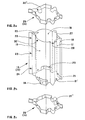
- the substantially cylindrical portion or body 13 of the case 14 of FIG. 2a comprises two parts 15 and 16 hinged together around a hinge zone 17 centered on a longitudinal folding edge 18, and it comprises two lower external cells 19 and 20 provided to cover the movable supports 11 of the stack of lids 12 ( Figure 1) during the coating operation.
- This portion 13 also carries 4 interior protuberances such as 21, obtained by permanent deformation of the wall and corresponding to hollows in the exterior surface. These protuberances or bulbs 21 located slightly below the top of the cells 19 and 20, serve as means for stopping the stack of lids coated with the portion 13 when extracted from the outlet store.
- the two parts 15 and 16 of the portion 13 of the case are closed by clipping at three points 22, 23 and 24. They then comprise three longitudinal cells 25, 26, 27 which have to surround the guide rods 9 externally (FIG. 1), one of these cells 25 being produced by closing the portion 13.
- the external recesses 21 ′ corresponding to the internal protuberances 21 serve for fixing the lower cover 28 (FIG. 2c) by interlocking, this cover 28 carrying similar protrusions 21 ".
- the upper cover 29 (FIG. 2a) has the same shape as the cover lower 28, the two covers are interchangeable, and the top of the case portion 13 and the cover 29 carry fixing reliefs 30 ' and 30 " similar to the reliefs 21 ' and 21".
- the cylindrical portion 31 of this second case has, like the portion 13 of the first case, three longitudinal cells 25, 26, 27 externally enveloping the guide rods 9 (Figure 4). It has as support means on the mobile supports 11 of the outlet store two U-shaped notches 32 and 33 of its wall in its end part 325, the bottoms 320 and 330 of these notches then resting on the supports 11 when the The case is placed on the outlet magazine by sliding around the guide rods 9 ( Figures 3 and 4).
- the portion 31 also has two pairs of opposite incisions 34, 34 'and 35, 35', making it possible to thread a through stop blade 36 just below the stack of lids supported on the mobile supports 11, the doubling these incisions allowing the operator to use as the first incision 34 that which is best placed for him.
- FIG. 4 shows how the cylindrical portion 31 contains the outline 37 (dotted line) of the lids, independently of the three guide rods 9 and with a small clearance, here from 0.5 to 0.8 mm in diameter, depending on the zones included between the longitudinal cells 25,
- This case body 31 can be placed on the outlet magazine before, during or after it is filled with the lids, which gives flexibility for operator interventions. After extraction of the case body 31 filled with lids, it is provided with end covers fitted with forcing or with suitable fixing means.
- the case body 31 is here in extruded PVC 1.5 mm thick, its overall dimensions in cross section are 92x68.5 mm and its total height is 132 mm, the height of its support notches 32 and 33 being 10 mm. Its incisions 34 to 35 'are located 8.5 mm from its upper end, they have a height of 1.2 mm and a width or unit length of 10 mm, the stop blade 36 used being made of stainless steel with rounded angles of dimensions 95x8.5x 1 mm.
- This case was used with embossed and decorated 0.04 mm thick aluminum lids, which gave them an apparent thickness of 0.08 mm having the outline 37 of FIG. 4, corresponding to a circle with a diameter of 68 mm. connected to a radiated right angle sector (radius of 5 mm).
- the lids are packaged in stacks of 1,500 pre-stacked lids and counted automatically in the machine's stacking chamber, weighing 585 g and height 120 mm, in the cases provided with lids, and handled as such until put on the customer's packaging machine, described above, for which the case makes it possible to avoid any pollution of the lids.
Landscapes
- Engineering & Computer Science (AREA)
- Mechanical Engineering (AREA)
- Architecture (AREA)
- Structural Engineering (AREA)
- Closing Of Containers (AREA)
- Container Filling Or Packaging Operations (AREA)
- Solid-Sorbent Or Filter-Aiding Compositions (AREA)
- External Artificial Organs (AREA)
- Auxiliary Devices For And Details Of Packaging Control (AREA)
- Hydroponics (AREA)
- Position Input By Displaying (AREA)
- Measurement Of Velocity Or Position Using Acoustic Or Ultrasonic Waves (AREA)
- Coupling Device And Connection With Printed Circuit (AREA)
- Cultivation Receptacles Or Flower-Pots, Or Pots For Seedlings (AREA)
- Catching Or Destruction (AREA)
- Diaphragms For Electromechanical Transducers (AREA)
- Transition And Organic Metals Composition Catalysts For Addition Polymerization (AREA)
- Stacking Of Articles And Auxiliary Devices (AREA)
Claims (13)
Priority Applications (1)
| Application Number | Priority Date | Filing Date | Title |
|---|---|---|---|
| AT88420202T ATE58691T1 (de) | 1987-06-17 | 1988-06-15 | Verpackungsverfahren, -system und -schachtel fuer deckel. |
Applications Claiming Priority (2)
| Application Number | Priority Date | Filing Date | Title |
|---|---|---|---|
| FR8708894 | 1987-06-17 | ||
| FR8708894A FR2616749B1 (fr) | 1987-06-17 | 1987-06-17 | Procede, systeme et etui de conditionnement d'opercules |
Publications (2)
| Publication Number | Publication Date |
|---|---|
| EP0296993A1 EP0296993A1 (de) | 1988-12-28 |
| EP0296993B1 true EP0296993B1 (de) | 1990-11-28 |
Family
ID=9352456
Family Applications (1)
| Application Number | Title | Priority Date | Filing Date |
|---|---|---|---|
| EP88420202A Expired - Lifetime EP0296993B1 (de) | 1987-06-17 | 1988-06-15 | Verpackungsverfahren, -system und -schachtel für Deckel |
Country Status (9)
| Country | Link |
|---|---|
| US (1) | US4942718A (de) |
| EP (1) | EP0296993B1 (de) |
| AT (1) | ATE58691T1 (de) |
| CA (1) | CA1295347C (de) |
| DE (1) | DE3861171D1 (de) |
| DK (1) | DK163727C (de) |
| ES (1) | ES2018884B3 (de) |
| FI (1) | FI84798C (de) |
| FR (1) | FR2616749B1 (de) |
Families Citing this family (4)
| Publication number | Priority date | Publication date | Assignee | Title |
|---|---|---|---|---|
| US5211674A (en) * | 1992-03-11 | 1993-05-18 | Phoenix Enterprise Associates, Ltd. | Method and apparatus for packaging tape rolls |
| FR2730470B1 (fr) * | 1995-02-14 | 1997-03-21 | Pechiney Emballage Alimentaire | Procede de conditionnement d'opercules et etuis obtenus par le procede |
| ES2355141T3 (es) * | 2004-02-20 | 2011-03-23 | Arol S.P.A. | Cabeza de encapsulado para aplicar cápsulas roscadas. |
| CN111532463B (zh) * | 2020-04-16 | 2021-12-31 | 上海七感食品有限公司 | 一种菌种袋辅助液体接菌设备 |
Family Cites Families (11)
| Publication number | Priority date | Publication date | Assignee | Title |
|---|---|---|---|---|
| CA542433A (en) * | 1957-06-18 | Ex-Cell-O Corporation | Container nesting mechanism | |
| US1098061A (en) * | 1909-03-03 | 1914-05-26 | Brown Binnian Company | Finishing, assorting, and packaging machine. |
| US1463229A (en) * | 1920-07-15 | 1923-07-31 | United Shoe Machinery Corp | Cutting machine |
| US2119561A (en) * | 1934-03-17 | 1938-06-07 | American Can Co | Method of measuring and packing press articles and press attachment used therein |
| US2433535A (en) * | 1944-08-12 | 1947-12-30 | Jacob J Treis | Apparatus for cutting and packaging sheets of material |
| US2556214A (en) * | 1946-10-30 | 1951-06-12 | American Can Co | Counting, stacking, and packing machine |
| GB908433A (en) * | 1959-10-28 | 1962-10-17 | Aluminum Co Of America | Article handling mechanism |
| US3261500A (en) * | 1964-04-15 | 1966-07-19 | Continental Can Co | Disposable foam plastic cup dispenser |
| FR1496782A (fr) * | 1966-08-23 | 1967-10-06 | Machine automatique d'empilage et de comptage d'objets | |
| US3466833A (en) * | 1966-11-22 | 1969-09-16 | Maryland Plastics Inc | Package,packaging machine and method |
| IT1125261B (it) * | 1976-02-13 | 1986-05-14 | Ind Macchine Automatiche Spa I | Procedimento per la produzione e il raggruppamento di tavolette termoformate in materiale plastico e macchina per attuare tale procedimento |
-
1987
- 1987-06-17 FR FR8708894A patent/FR2616749B1/fr not_active Expired
-
1988
- 1988-05-27 US US07/199,787 patent/US4942718A/en not_active Expired - Fee Related
- 1988-06-15 DE DE8888420202T patent/DE3861171D1/de not_active Expired - Lifetime
- 1988-06-15 ES ES88420202T patent/ES2018884B3/es not_active Expired - Lifetime
- 1988-06-15 EP EP88420202A patent/EP0296993B1/de not_active Expired - Lifetime
- 1988-06-15 AT AT88420202T patent/ATE58691T1/de active
- 1988-06-16 DK DK329788A patent/DK163727C/da not_active IP Right Cessation
- 1988-06-16 FI FI882893A patent/FI84798C/fi not_active IP Right Cessation
- 1988-06-16 CA CA000569648A patent/CA1295347C/fr not_active Expired - Fee Related
Also Published As
| Publication number | Publication date |
|---|---|
| US4942718A (en) | 1990-07-24 |
| FI84798B (fi) | 1991-10-15 |
| FI882893A0 (fi) | 1988-06-16 |
| FI84798C (fi) | 1992-01-27 |
| ES2018884B3 (es) | 1991-05-16 |
| DK163727B (da) | 1992-03-30 |
| ATE58691T1 (de) | 1990-12-15 |
| FI882893A7 (fi) | 1988-12-18 |
| EP0296993A1 (de) | 1988-12-28 |
| DE3861171D1 (de) | 1991-01-10 |
| CA1295347C (fr) | 1992-02-04 |
| DK329788D0 (da) | 1988-06-16 |
| FR2616749B1 (fr) | 1989-09-29 |
| DK329788A (da) | 1988-12-18 |
| DK163727C (da) | 1992-09-07 |
| FR2616749A1 (fr) | 1988-12-23 |
Similar Documents
| Publication | Publication Date | Title |
|---|---|---|
| EP1312548B1 (de) | Vorrichtung zum Ausschneiden einer Reihe von Membranverschlüssen aus einer Bahn und zur Fixierung dieser auf einer Reihe von gefüllten Behältern | |
| WO2011010057A1 (fr) | Perfectionnement a une installation de palettisation combinee avec acces securise. | |
| FR2492318A1 (fr) | Procede et dispositif de dechargement d'emboutis en forme de coupe a partir d'une presse a decouper et a emboutir | |
| EP0296993B1 (de) | Verpackungsverfahren, -system und -schachtel für Deckel | |
| EP2809601B1 (de) | Verfahren zur probenentnahme in einer verpackungsmaschine für flache gegenstände, und verpackungsmaschine für die umsetzung dieses verfahrens | |
| EP0645309B1 (de) | Verfahren und Vorrichtung zur Anpassung der Höhe einer Verpackung an die Höhe ihres Inhalts und Schneidevorrichtung dafür | |
| FR2600049A1 (fr) | Dispositif de retenue d'un objet a l'entree d'un canal d'empilement. | |
| FR2513081A1 (fr) | Procede et dispositif pour sectionner transversalement des poissons | |
| EP3797968B1 (de) | Vorrichtung zum thermoformen, folienverschliessen und schneiden von behähltern von unterschiedlichen grössen | |
| CH391577A (fr) | Procédé de transfert de corps creux et dispositif pour sa mise en oeuvre | |
| FR2676941A1 (fr) | Module de case pour machine de tri. | |
| FR2730210A1 (fr) | Machine a poser des manchons de filets mailles sur des objets | |
| EP3339201B1 (de) | Vorrichtung zum aufmachen von ballen | |
| FR2644425A1 (fr) | Dispositif de separation des recipients remplis dans une installation de conditionnement d'emballages a partir d'une bande thermoplastique | |
| EP3532389B1 (de) | Verfahren und vorrichtungen zum befüllen von töpfen, topfverpackungslinien | |
| EP0516556B1 (de) | Verfahren zum Thermoverformen und eventuell weiteren Verpacken von Behältern und Maschine dafür | |
| EP0352165B1 (de) | Vorrichtung zum Formen von Käsestücken und zum automatischen Umdrehen von mit Käsemasse gefüllten Formen | |
| FR2515140A1 (fr) | Procede pour le maintien d'articles relativement a un plateau et moyens pour sa mise en oeuvre | |
| FR2799433A1 (fr) | Procede et dispositif pour l'emballage de produit bobine, en particulier de rouleaux de film plastique | |
| FR2496599A1 (fr) | Emballage fractionnable | |
| FR2468507A1 (fr) | Machine automatique pour l'emballage et la mise en boite de fromages et produits similaires | |
| FR2941679A1 (fr) | Procede et machine pour le dechargement de palettes. | |
| FR2608559A1 (fr) | Chargeur destine a l'alimentation verticale du magasin d'une machine de traitement de produits en plaques, procede d'utilisation de ce chargeur et installation de mise en oeuvre de ce procede | |
| FR2553058A1 (fr) | Appareil de palettisation de sacs, appareil de manipulation de sacs, appareil pour entrelacer une bande continue de feuillard et procede de manipulation et de pose d'articles sur une palette | |
| FR2664245A1 (fr) | Procede de palettisation semi-automatique et automatique d'emballages en bois et machine de mise en óoeuvre de ce procede. |
Legal Events
| Date | Code | Title | Description |
|---|---|---|---|
| PUAI | Public reference made under article 153(3) epc to a published international application that has entered the european phase |
Free format text: ORIGINAL CODE: 0009012 |
|
| AK | Designated contracting states |
Kind code of ref document: A1 Designated state(s): AT BE CH DE ES GB IT LI LU NL SE |
|
| 17P | Request for examination filed |
Effective date: 19890111 |
|
| 17Q | First examination report despatched |
Effective date: 19900511 |
|
| GRAA | (expected) grant |
Free format text: ORIGINAL CODE: 0009210 |
|
| AK | Designated contracting states |
Kind code of ref document: B1 Designated state(s): AT BE CH DE ES GB IT LI LU NL SE |
|
| REF | Corresponds to: |
Ref document number: 58691 Country of ref document: AT Date of ref document: 19901215 Kind code of ref document: T |
|
| ITF | It: translation for a ep patent filed | ||
| REF | Corresponds to: |
Ref document number: 3861171 Country of ref document: DE Date of ref document: 19910110 |
|
| GBT | Gb: translation of ep patent filed (gb section 77(6)(a)/1977) | ||
| PLBE | No opposition filed within time limit |
Free format text: ORIGINAL CODE: 0009261 |
|
| STAA | Information on the status of an ep patent application or granted ep patent |
Free format text: STATUS: NO OPPOSITION FILED WITHIN TIME LIMIT |
|
| 26N | No opposition filed | ||
| ITTA | It: last paid annual fee | ||
| EPTA | Lu: last paid annual fee | ||
| EAL | Se: european patent in force in sweden |
Ref document number: 88420202.9 |
|
| PGFP | Annual fee paid to national office [announced via postgrant information from national office to epo] |
Ref country code: GB Payment date: 19960514 Year of fee payment: 9 |
|
| PGFP | Annual fee paid to national office [announced via postgrant information from national office to epo] |
Ref country code: SE Payment date: 19960520 Year of fee payment: 9 Ref country code: DE Payment date: 19960520 Year of fee payment: 9 |
|
| PGFP | Annual fee paid to national office [announced via postgrant information from national office to epo] |
Ref country code: AT Payment date: 19960523 Year of fee payment: 9 |
|
| PGFP | Annual fee paid to national office [announced via postgrant information from national office to epo] |
Ref country code: CH Payment date: 19960529 Year of fee payment: 9 |
|
| PGFP | Annual fee paid to national office [announced via postgrant information from national office to epo] |
Ref country code: BE Payment date: 19960531 Year of fee payment: 9 |
|
| PGFP | Annual fee paid to national office [announced via postgrant information from national office to epo] |
Ref country code: LU Payment date: 19960601 Year of fee payment: 9 |
|
| PGFP | Annual fee paid to national office [announced via postgrant information from national office to epo] |
Ref country code: ES Payment date: 19960627 Year of fee payment: 9 |
|
| PGFP | Annual fee paid to national office [announced via postgrant information from national office to epo] |
Ref country code: NL Payment date: 19960630 Year of fee payment: 9 |
|
| PG25 | Lapsed in a contracting state [announced via postgrant information from national office to epo] |
Ref country code: LU Free format text: LAPSE BECAUSE OF NON-PAYMENT OF DUE FEES Effective date: 19970615 Ref country code: GB Free format text: LAPSE BECAUSE OF NON-PAYMENT OF DUE FEES Effective date: 19970615 Ref country code: AT Effective date: 19970615 |
|
| PG25 | Lapsed in a contracting state [announced via postgrant information from national office to epo] |
Ref country code: SE Effective date: 19970616 Ref country code: ES Free format text: LAPSE BECAUSE OF NON-PAYMENT OF DUE FEES Effective date: 19970616 |
|
| PG25 | Lapsed in a contracting state [announced via postgrant information from national office to epo] |
Ref country code: LI Free format text: LAPSE BECAUSE OF NON-PAYMENT OF DUE FEES Effective date: 19970630 Ref country code: CH Free format text: LAPSE BECAUSE OF NON-PAYMENT OF DUE FEES Effective date: 19970630 Ref country code: BE Effective date: 19970630 |
|
| BERE | Be: lapsed |
Owner name: CEBAL Effective date: 19970630 |
|
| PG25 | Lapsed in a contracting state [announced via postgrant information from national office to epo] |
Ref country code: NL Effective date: 19980101 |
|
| GBPC | Gb: european patent ceased through non-payment of renewal fee |
Effective date: 19970615 |
|
| REG | Reference to a national code |
Ref country code: CH Ref legal event code: PL |
|
| EUG | Se: european patent has lapsed |
Ref document number: 88420202.9 |
|
| NLV4 | Nl: lapsed or anulled due to non-payment of the annual fee |
Effective date: 19980101 |
|
| PG25 | Lapsed in a contracting state [announced via postgrant information from national office to epo] |
Ref country code: DE Free format text: LAPSE BECAUSE OF NON-PAYMENT OF DUE FEES Effective date: 19980303 |
|
| REG | Reference to a national code |
Ref country code: ES Ref legal event code: FD2A Effective date: 20000503 |
|
| PG25 | Lapsed in a contracting state [announced via postgrant information from national office to epo] |
Ref country code: IT Free format text: LAPSE BECAUSE OF NON-PAYMENT OF DUE FEES;WARNING: LAPSES OF ITALIAN PATENTS WITH EFFECTIVE DATE BEFORE 2007 MAY HAVE OCCURRED AT ANY TIME BEFORE 2007. THE CORRECT EFFECTIVE DATE MAY BE DIFFERENT FROM THE ONE RECORDED. Effective date: 20050615 |