EP0295201B1 - Spreizdübel mit begrenzter Spreizung - Google Patents
Spreizdübel mit begrenzter Spreizung Download PDFInfo
- Publication number
- EP0295201B1 EP0295201B1 EP88810277A EP88810277A EP0295201B1 EP 0295201 B1 EP0295201 B1 EP 0295201B1 EP 88810277 A EP88810277 A EP 88810277A EP 88810277 A EP88810277 A EP 88810277A EP 0295201 B1 EP0295201 B1 EP 0295201B1
- Authority
- EP
- European Patent Office
- Prior art keywords
- expansion
- expansible
- stop shoulder
- bore
- dowel
- Prior art date
- Legal status (The legal status is an assumption and is not a legal conclusion. Google has not performed a legal analysis and makes no representation as to the accuracy of the status listed.)
- Expired - Lifetime
Links
- 230000007704 transition Effects 0.000 claims abstract description 4
- 238000006073 displacement reaction Methods 0.000 description 3
- 238000000034 method Methods 0.000 description 2
- 230000004323 axial length Effects 0.000 description 1
- 230000006378 damage Effects 0.000 description 1
- 230000003247 decreasing effect Effects 0.000 description 1
- 238000010586 diagram Methods 0.000 description 1
Images

Classifications
-
- F—MECHANICAL ENGINEERING; LIGHTING; HEATING; WEAPONS; BLASTING
- F16—ENGINEERING ELEMENTS AND UNITS; GENERAL MEASURES FOR PRODUCING AND MAINTAINING EFFECTIVE FUNCTIONING OF MACHINES OR INSTALLATIONS; THERMAL INSULATION IN GENERAL
- F16B—DEVICES FOR FASTENING OR SECURING CONSTRUCTIONAL ELEMENTS OR MACHINE PARTS TOGETHER, e.g. NAILS, BOLTS, CIRCLIPS, CLAMPS, CLIPS OR WEDGES; JOINTS OR JOINTING
- F16B13/00—Dowels or other devices fastened in walls or the like by inserting them in holes made therein for that purpose
- F16B13/04—Dowels or other devices fastened in walls or the like by inserting them in holes made therein for that purpose with parts gripping in the hole or behind the reverse side of the wall after inserting from the front
- F16B13/06—Dowels or other devices fastened in walls or the like by inserting them in holes made therein for that purpose with parts gripping in the hole or behind the reverse side of the wall after inserting from the front combined with expanding sleeve
- F16B13/063—Dowels or other devices fastened in walls or the like by inserting them in holes made therein for that purpose with parts gripping in the hole or behind the reverse side of the wall after inserting from the front combined with expanding sleeve by the use of an expander
- F16B13/066—Dowels or other devices fastened in walls or the like by inserting them in holes made therein for that purpose with parts gripping in the hole or behind the reverse side of the wall after inserting from the front combined with expanding sleeve by the use of an expander fastened by extracting a separate expander-part, actuated by the screw, nail or the like
Definitions
- the invention relates to an expansion dowel with an expansion sleeve having a longitudinally slotted area and a truncated cone-shaped expansion body which can be drawn into this area from the front end, the expansion sleeve having a length-extending bore which extends within the slotted area in accordance with the expansion body front end flared.
- Expansion anchors of the type mentioned, for example from DE-C 2 536 137 have a post-expansion behavior in use and are used primarily in the middle and upper load range. For certain applications, such as fastenings in the crack-prone tensile zone of a building, these dowels cannot be used without further ado. If a crack runs directly through the borehole, it can be widened so much when the anchor is expanded that the anchorage value of the anchor drops significantly. In extreme cases, this over-spreading of the dowel can also lead to chipping or destruction of the structure and thus to failure of the dowel.
- the invention has for its object to provide an expansion dowel that has a limited expansion behavior.
- this is achieved in that within the slotted area, subsequent to the conical extension towards the rear end, there is a cylindrical bore region whose diameter corresponds to the smallest diameter of the conical extension and exceeds the diameter of the remaining rear part of the bore of the expansion sleeve .
- the expansion sleeve expands relatively strongly under tensile load. Due to the conicity of the expanding area corresponding to that of the expansion body, this expansion of the expansion sleeve takes place approximately parallel to the longitudinal axis of the expansion anchor. If the expansion body reaches the cylindrical bore area of the expansion sleeve, the expansion sleeve is subsequently expanded when there is tensile load on the expansion body. However, this is less than if the expansion body is located in the expanding area of the expansion sleeve. When the dowel is pre-spread, this is also noticeable by a smaller increase in the tensile force to be applied or the torque to be applied. The expansion path is limited by the axial length of the cylindrical area.
- the transition from the cylindrical bore area to the remaining rear part of the bore of the expansion sleeve as a stop shoulder for the expansion body. If the expansion body already hits the stop shoulder during pre-expansion, this is noticeable by a sudden sharp increase in the pre-tensioning force to be applied. By partially deforming the stop shoulder, an overstressing of the expansion anchor can be avoided.
- the stop shoulder advantageously runs essentially perpendicular to the longitudinal axis of the dowel, so that a flat contact surface is created for the expansion body.
- the axial pressure occurring when the expansion body comes up against the stop shoulder is distributed uniformly over the circumference of the rear end face of the expansion body.
- the stop shoulder is expediently curved in a concave manner. At the end of the re-expansion process, this enables the expansion body to gently run up against the stop shoulder. The expansion body thus slides over the concave curved shoulder and is centered at the same time. In the case of a sharp-edged expanding body, there is initially only a line contact between the expanding body and the stop shoulder. By deformation of the expansion body on the one hand and the stop shoulder on the other hand, however, over time the surface of the expansion body rests on the expansion sleeve in the axial direction.
- the curvature of the stop shoulder can be constant or variable, the radius of curvature preferably decreasing in the direction of the rear end of the expansion sleeve.
- the stop shoulder is inclined to the longitudinal axis of the dowel. This inclination of the stop shoulder can be directed towards the front or rear end of the expansion sleeve. An inclination towards the front end of the expansion sleeve creates a conical countersink in the manner of a valve seat. If the inclination of the stop shoulder is directed towards the rear end of the expansion sleeve, an annular projection is formed on the stop shoulder, which can be deformed when the expanding body comes up. Such a deformation zone prevents the anchor from being overstressed.
- the length of the conical widening of the expansion sleeve expediently corresponds essentially to the length of the truncated cone-shaped expansion body.
- Such a dimensioning means that the expansion body is completely in the expansion sleeve at the end of the first expansion phase in the area of the conical widening.
- the foremost part of the expansion sleeve is then no longer in the area of the expansion body and can therefore deform back somewhat. This further facilitates the retraction of the expansion body in the second phase.
- the length of the cylindrical bore region advantageously corresponds essentially to the length of the truncated cone-shaped expansion body.
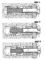
- the expansion dowel according to the invention shown in FIGS. 1 to 3 essentially consists of an expansion sleeve, generally designated 1, with a front end 1 a and a rear end 1 b, and a retractable into the front end 1 a of the expansion sleeve 1, with a total of 2 designated expansion body.
- the expansion sleeve 1 has a continuous bore 1 c and longitudinal slots 1d extending from the front end 1 a and extending over part of the length of the expansion sleeve 1.
- the foremost part of the bore 1c is designed as a conical widening 1 with a diameter increasing towards the front end 1a.
- a conical extension 1f adjoins the conical extension 1f, the diameter of which corresponds to the smallest diameter of the conical extension 1e.
- the cylindrical bore area 1f exceeds the diameter of the bore 1c of the expansion sleeve 1, so that a stop shoulder 1g is formed at the rear end of the cylindrical bore area 1f.
- the expansion sleeve 1 is inserted into a borehole 3a of a receiving material, designated overall by 3. After the expansion dowel has been inserted into the receiving material 3, a screw, generally designated 4, is inserted through a component 5 to be fastened into the expansion sleeve 1 and screwed into an internal thread 2a of the expansion body 2.
- a washer 6 is arranged between a head 4a of the screw 4 and the component 5 to be fastened.
- the expansion body 2 has been drawn into the expansion sleeve 1 up to the rear end of the conical extension 1. If an additional load now occurs on the screw 4, the expansion body 2 is also drawn into the cylindrical bore area 1f. The end of this process is shown in Fig. 3. The rear end of the expansion body 2 has accrued on the stop shoulder 1g. The maximum possible radial expandability of the expansion sleeve 1 is thus achieved. If the screw 4 is subjected to further tensile loads, only the stop shoulder 1g can be deformed.
- FIGS. 5 and 6 show further expansion sleeves, designated overall by 11 and 21. These differ from the embodiment shown in FIGS. 1 to 3 only in the design of the stop shoulder. Corresponding reference numbers have been increased by ten or twenty.
- the stop shoulder 11g shown in FIG. 5 is concavely curved. With such a configuration of the stop shoulder 11g, the expansion of the expansion body 2 on the stop shoulder 11g g can be controlled, for example, so that it does not take place hard and suddenly, as in the case of the stop shoulder 1g, which runs essentially perpendicular to the longitudinal axis of the dowel, but softly and gradually.
- the radius of curvature of the stop shoulder 11 can remain constant or change in the entire area.
- the stop shoulder 21g is inclined to the longitudinal axis of the dowel.
- the inclination of the stop shoulder 21g is directed in such a way that a kind of undercut or a projection is formed. This projection can be deformed when the expansion body 2 comes up.
- This embodiment also results in a soft emergence of the expansion body 2 on the expansion sleeve 21.
Landscapes
- General Engineering & Computer Science (AREA)
- Engineering & Computer Science (AREA)
- Mechanical Engineering (AREA)
- Dowels (AREA)
- Joining Of Building Structures In Genera (AREA)
- Preparation Of Fruits And Vegetables (AREA)
- Closures For Containers (AREA)
- Processing Of Stones Or Stones Resemblance Materials (AREA)
- Orthopedics, Nursing, And Contraception (AREA)
- Thermotherapy And Cooling Therapy Devices (AREA)
- Coating Apparatus (AREA)
- Pharmaceuticals Containing Other Organic And Inorganic Compounds (AREA)
- Road Signs Or Road Markings (AREA)
- Finger-Pressure Massage (AREA)
Priority Applications (1)
| Application Number | Priority Date | Filing Date | Title |
|---|---|---|---|
| AT88810277T ATE52311T1 (de) | 1987-06-09 | 1988-04-29 | Spreizduebel mit begrenzter spreizung. |
Applications Claiming Priority (2)
| Application Number | Priority Date | Filing Date | Title |
|---|---|---|---|
| DE3719164 | 1987-06-09 | ||
| DE19873719164 DE3719164A1 (de) | 1987-06-09 | 1987-06-09 | Spreizduebel mit begrenzter spreizung |
Publications (2)
| Publication Number | Publication Date |
|---|---|
| EP0295201A1 EP0295201A1 (de) | 1988-12-14 |
| EP0295201B1 true EP0295201B1 (de) | 1990-04-25 |
Family
ID=6329300
Family Applications (1)
| Application Number | Title | Priority Date | Filing Date |
|---|---|---|---|
| EP88810277A Expired - Lifetime EP0295201B1 (de) | 1987-06-09 | 1988-04-29 | Spreizdübel mit begrenzter Spreizung |
Country Status (11)
| Country | Link |
|---|---|
| US (1) | US4869631A (fi) |
| EP (1) | EP0295201B1 (fi) |
| JP (2) | JPS63312503A (fi) |
| AT (1) | ATE52311T1 (fi) |
| AU (1) | AU605068B2 (fi) |
| CA (1) | CA1303884C (fi) |
| DE (2) | DE3719164A1 (fi) |
| DK (1) | DK165065C (fi) |
| ES (1) | ES2014511B3 (fi) |
| FI (1) | FI90280C (fi) |
| MX (1) | MX169082B (fi) |
Families Citing this family (9)
| Publication number | Priority date | Publication date | Assignee | Title |
|---|---|---|---|---|
| US5033909A (en) * | 1990-04-27 | 1991-07-23 | Ingersoll-Rand Company | Coupling for anchor rod and sleeve |
| EP0503677A3 (en) * | 1991-03-14 | 1993-01-13 | Maechtle Gmbh | Heavy duty anchor |
| DE19820140A1 (de) * | 1998-05-06 | 1999-11-11 | Adolf Wuerth Gmbh & Co Kg | Befestigung von Masten für Ampeln oder dergleichen |
| DE19921148A1 (de) * | 1999-05-07 | 2000-11-09 | Hilti Ag | Schienenfuß für ein Diamantschneidesystem |
| US20020194718A1 (en) * | 2001-06-21 | 2002-12-26 | David Yekutiely | Anchoring system and methods therefor |
| DE10134604A1 (de) * | 2001-07-17 | 2003-02-06 | Hilti Ag | Spreizdübel |
| FR2947592B1 (fr) * | 2009-07-06 | 2015-05-15 | Airbus Operations Sas | Dispositif de liaison mecanique d'au moins deux pieces a alesages coaxiaux |
| CN107366667A (zh) * | 2017-08-04 | 2017-11-21 | 索菲亚家居股份有限公司 | 快装连接件 |
| EP3536984A1 (de) * | 2018-03-05 | 2019-09-11 | HILTI Aktiengesellschaft | Spreizanker mit zusatzspreizkörper |
Family Cites Families (18)
| Publication number | Priority date | Publication date | Assignee | Title |
|---|---|---|---|---|
| US1755264A (en) * | 1929-02-25 | 1930-04-22 | American Bolt Anchor Corp | Means for anchoring bolts |
| US1959439A (en) * | 1931-12-02 | 1934-05-22 | Edward Ogden Company Inc J | Expansion shield or bolt anchor |
| US2319376A (en) * | 1942-08-24 | 1943-05-18 | Herman H Helbush | Rivet |
| GB906615A (en) * | 1960-03-31 | 1962-09-26 | Robert Kearsley Baker | Improvements in or relating to expansion sockets |
| CH433671A (de) * | 1964-06-12 | 1967-04-15 | Gerhard Anton | Vorrichtung zum Verbinden von Fenster- oder Türrahmen oder dergleichen mit dem Mauerwerk |
| CH483571A (de) * | 1967-11-22 | 1969-12-31 | Schmid Arthur | Dübel |
| JPS4843823U (fi) * | 1971-09-27 | 1973-06-07 | ||
| DE2150572A1 (de) * | 1971-10-11 | 1973-04-19 | Willi Schober | Spreizduebel |
| DE2249762C3 (de) * | 1972-10-11 | 1980-05-08 | Heinrich 6102 Pfungstadt Liebig | Doppelt spreizender Dübel |
| DE2501925C3 (de) * | 1975-01-18 | 1979-07-26 | Heinrich B. 2800 Bremen Schaefers | Dübel |
| DE2536137C2 (de) * | 1975-08-13 | 1986-04-10 | Hilti Ag, Schaan | Spreizdübel |
| DE2834241A1 (de) * | 1978-08-04 | 1980-02-28 | Volker Hainke | Ankerbolzen |
| AU533341B2 (en) * | 1979-12-18 | 1983-11-17 | Volken Hainke | Foundation bolt |
| CH644190A5 (de) * | 1980-03-05 | 1984-07-13 | Julius Murbach | Duebel. |
| FR2506867A1 (fr) * | 1981-05-29 | 1982-12-03 | Shur Lok International Sa | Dispositif d'implantation d'une vis freinee ou d'un goujon dans un trou borgne |
| GB2139726B (en) * | 1983-05-12 | 1986-08-20 | Tucker Fasteners Ltd | Bolt anchor |
| US4627775A (en) * | 1983-09-01 | 1986-12-09 | Huck Manufacturing Company | Blind fastener with grip compensating means |
| DE3335628A1 (de) * | 1983-09-30 | 1985-04-04 | Hilti Ag, Schaan | Spreizduebel mit einziehbarem spreizkoerper |
-
1987
- 1987-06-09 DE DE19873719164 patent/DE3719164A1/de not_active Withdrawn
-
1988
- 1988-04-29 EP EP88810277A patent/EP0295201B1/de not_active Expired - Lifetime
- 1988-04-29 ES ES88810277T patent/ES2014511B3/es not_active Expired - Lifetime
- 1988-04-29 DE DE8888810277T patent/DE3860108D1/de not_active Expired - Fee Related
- 1988-04-29 AT AT88810277T patent/ATE52311T1/de not_active IP Right Cessation
- 1988-05-27 DK DK292788A patent/DK165065C/da not_active IP Right Cessation
- 1988-05-31 US US07/200,640 patent/US4869631A/en not_active Expired - Lifetime
- 1988-06-01 CA CA000568346A patent/CA1303884C/en not_active Expired - Fee Related
- 1988-06-06 FI FI882654A patent/FI90280C/fi not_active IP Right Cessation
- 1988-06-07 AU AU17464/88A patent/AU605068B2/en not_active Ceased
- 1988-06-08 MX MX011816A patent/MX169082B/es unknown
- 1988-06-08 JP JP63139578A patent/JPS63312503A/ja active Pending
-
1996
- 1996-08-20 JP JP1996008382U patent/JP2572758Y2/ja not_active Expired - Lifetime
Also Published As
| Publication number | Publication date |
|---|---|
| US4869631A (en) | 1989-09-26 |
| FI90280C (fi) | 1994-01-10 |
| DE3719164A1 (de) | 1988-12-29 |
| JPH09274U (ja) | 1997-05-16 |
| ATE52311T1 (de) | 1990-05-15 |
| DE3860108D1 (de) | 1990-05-31 |
| FI882654A0 (fi) | 1988-06-06 |
| AU605068B2 (en) | 1991-01-03 |
| MX169082B (es) | 1993-06-21 |
| JPS63312503A (ja) | 1988-12-21 |
| CA1303884C (en) | 1992-06-23 |
| FI882654A (fi) | 1988-12-10 |
| ES2014511B3 (es) | 1990-07-16 |
| DK165065C (da) | 1993-02-22 |
| DK292788A (da) | 1988-12-10 |
| AU1746488A (en) | 1988-12-15 |
| DK292788D0 (da) | 1988-05-27 |
| JP2572758Y2 (ja) | 1998-05-25 |
| EP0295201A1 (de) | 1988-12-14 |
| FI90280B (fi) | 1993-09-30 |
| DK165065B (da) | 1992-10-05 |
Similar Documents
| Publication | Publication Date | Title |
|---|---|---|
| EP0308619B1 (de) | Spreizdübel | |
| DE3420375C2 (de) | Dübel | |
| EP0318426B1 (de) | Spreizdübel mit Spreizhülse und einziehbarem Spreizkegel | |
| EP0905385B1 (de) | Spreizdübel | |
| DE68908607T2 (de) | Blindniet. | |
| EP0134391B1 (de) | Spreizanker | |
| DE2617191A1 (de) | Spreizduebel | |
| DE2657353C2 (fi) | ||
| DE68902323T2 (de) | Blindniet. | |
| EP0295201B1 (de) | Spreizdübel mit begrenzter Spreizung | |
| DE3413854C2 (fi) | ||
| EP0733813B1 (de) | Spreizdübel | |
| EP0306681A1 (de) | Verfahren zum Verankern eines Spreizdübels | |
| EP0723085A1 (de) | Spreizdübel | |
| DE19936090A1 (de) | Befestigungselement aus Metall | |
| EP0905386B1 (de) | Spreizdübel | |
| EP0289729B1 (de) | Befestigungselement | |
| CH663451A5 (de) | Spreizduebel mit keilfoermigem spreizelement. | |
| DE2744666A1 (de) | Befestigungselement zur verankerung in bauwerksteilen | |
| DD267536A5 (de) | Duebel mit spreizhuelse | |
| DE3538298A1 (de) | Schlagspreizduebel fuer die verankerung in konisch nach innen erweiterten bohrloechern | |
| DE2914074A1 (de) | Bauwerksanker fuer eine verankerung in einer bohrung | |
| EP0503677A2 (de) | Schwerlastanker | |
| EP0508096B1 (de) | Verfahren zur Herstellung eines Spreizdübels aus Metall | |
| DE9310356U1 (de) | Spreizduebel |
Legal Events
| Date | Code | Title | Description |
|---|---|---|---|
| PUAI | Public reference made under article 153(3) epc to a published international application that has entered the european phase |
Free format text: ORIGINAL CODE: 0009012 |
|
| AK | Designated contracting states |
Kind code of ref document: A1 Designated state(s): AT BE CH DE ES FR GB IT LI NL SE |
|
| 17P | Request for examination filed |
Effective date: 19890113 |
|
| 17Q | First examination report despatched |
Effective date: 19890814 |
|
| GRAA | (expected) grant |
Free format text: ORIGINAL CODE: 0009210 |
|
| AK | Designated contracting states |
Kind code of ref document: B1 Designated state(s): AT BE CH DE ES FR GB IT LI NL SE |
|
| REF | Corresponds to: |
Ref document number: 52311 Country of ref document: AT Date of ref document: 19900515 Kind code of ref document: T |
|
| ITF | It: translation for a ep patent filed | ||
| REF | Corresponds to: |
Ref document number: 3860108 Country of ref document: DE Date of ref document: 19900531 |
|
| ET | Fr: translation filed | ||
| GBT | Gb: translation of ep patent filed (gb section 77(6)(a)/1977) | ||
| PLBE | No opposition filed within time limit |
Free format text: ORIGINAL CODE: 0009261 |
|
| STAA | Information on the status of an ep patent application or granted ep patent |
Free format text: STATUS: NO OPPOSITION FILED WITHIN TIME LIMIT |
|
| 26N | No opposition filed | ||
| ITTA | It: last paid annual fee | ||
| EAL | Se: european patent in force in sweden |
Ref document number: 88810277.9 |
|
| PGFP | Annual fee paid to national office [announced via postgrant information from national office to epo] |
Ref country code: SE Payment date: 19990301 Year of fee payment: 12 Ref country code: BE Payment date: 19990301 Year of fee payment: 12 |
|
| PGFP | Annual fee paid to national office [announced via postgrant information from national office to epo] |
Ref country code: NL Payment date: 19990429 Year of fee payment: 12 |
|
| PGFP | Annual fee paid to national office [announced via postgrant information from national office to epo] |
Ref country code: FR Payment date: 20000411 Year of fee payment: 13 |
|
| PGFP | Annual fee paid to national office [announced via postgrant information from national office to epo] |
Ref country code: AT Payment date: 20000412 Year of fee payment: 13 |
|
| PGFP | Annual fee paid to national office [announced via postgrant information from national office to epo] |
Ref country code: ES Payment date: 20000419 Year of fee payment: 13 |
|
| PGFP | Annual fee paid to national office [announced via postgrant information from national office to epo] |
Ref country code: GB Payment date: 20000426 Year of fee payment: 13 |
|
| PGFP | Annual fee paid to national office [announced via postgrant information from national office to epo] |
Ref country code: CH Payment date: 20000427 Year of fee payment: 13 |
|
| PG25 | Lapsed in a contracting state [announced via postgrant information from national office to epo] |
Ref country code: SE Free format text: LAPSE BECAUSE OF NON-PAYMENT OF DUE FEES Effective date: 20000430 Ref country code: BE Free format text: LAPSE BECAUSE OF NON-PAYMENT OF DUE FEES Effective date: 20000430 |
|
| BERE | Be: lapsed |
Owner name: HILTI A.G. Effective date: 20000430 |
|
| PG25 | Lapsed in a contracting state [announced via postgrant information from national office to epo] |
Ref country code: NL Free format text: LAPSE BECAUSE OF NON-PAYMENT OF DUE FEES Effective date: 20001101 |
|
| EUG | Se: european patent has lapsed |
Ref document number: 88810277.9 |
|
| NLV4 | Nl: lapsed or anulled due to non-payment of the annual fee |
Effective date: 20001101 |
|
| PG25 | Lapsed in a contracting state [announced via postgrant information from national office to epo] |
Ref country code: GB Free format text: LAPSE BECAUSE OF NON-PAYMENT OF DUE FEES Effective date: 20010429 Ref country code: AT Free format text: LAPSE BECAUSE OF NON-PAYMENT OF DUE FEES Effective date: 20010429 |
|
| PG25 | Lapsed in a contracting state [announced via postgrant information from national office to epo] |
Ref country code: FR Free format text: THE PATENT HAS BEEN ANNULLED BY A DECISION OF A NATIONAL AUTHORITY Effective date: 20010430 Ref country code: ES Free format text: LAPSE BECAUSE OF NON-PAYMENT OF DUE FEES Effective date: 20010430 |
|
| PG25 | Lapsed in a contracting state [announced via postgrant information from national office to epo] |
Ref country code: LI Free format text: LAPSE BECAUSE OF NON-PAYMENT OF DUE FEES Effective date: 20010528 Ref country code: CH Free format text: LAPSE BECAUSE OF NON-PAYMENT OF DUE FEES Effective date: 20010528 |
|
| REG | Reference to a national code |
Ref country code: CH Ref legal event code: PL |
|
| GBPC | Gb: european patent ceased through non-payment of renewal fee |
Effective date: 20010429 |
|
| REG | Reference to a national code |
Ref country code: FR Ref legal event code: ST |
|
| PGFP | Annual fee paid to national office [announced via postgrant information from national office to epo] |
Ref country code: DE Payment date: 20020508 Year of fee payment: 15 |
|
| REG | Reference to a national code |
Ref country code: ES Ref legal event code: FD2A Effective date: 20030203 |
|
| PG25 | Lapsed in a contracting state [announced via postgrant information from national office to epo] |
Ref country code: DE Free format text: LAPSE BECAUSE OF NON-PAYMENT OF DUE FEES Effective date: 20031101 |
|
| PG25 | Lapsed in a contracting state [announced via postgrant information from national office to epo] |
Ref country code: IT Free format text: LAPSE BECAUSE OF NON-PAYMENT OF DUE FEES;WARNING: LAPSES OF ITALIAN PATENTS WITH EFFECTIVE DATE BEFORE 2007 MAY HAVE OCCURRED AT ANY TIME BEFORE 2007. THE CORRECT EFFECTIVE DATE MAY BE DIFFERENT FROM THE ONE RECORDED. Effective date: 20050429 |