EP0294754B1 - Process and apparatus for bonding two substantially flat elements - Google Patents
Process and apparatus for bonding two substantially flat elements Download PDFInfo
- Publication number
- EP0294754B1 EP0294754B1 EP88109032A EP88109032A EP0294754B1 EP 0294754 B1 EP0294754 B1 EP 0294754B1 EP 88109032 A EP88109032 A EP 88109032A EP 88109032 A EP88109032 A EP 88109032A EP 0294754 B1 EP0294754 B1 EP 0294754B1
- Authority
- EP
- European Patent Office
- Prior art keywords
- sealant
- balls
- application
- application nozzle
- outlet pipe
- Prior art date
- Legal status (The legal status is an assumption and is not a legal conclusion. Google has not performed a legal analysis and makes no representation as to the accuracy of the status listed.)
- Expired - Lifetime
Links
Images
Classifications
-
- C—CHEMISTRY; METALLURGY
- C09—DYES; PAINTS; POLISHES; NATURAL RESINS; ADHESIVES; COMPOSITIONS NOT OTHERWISE PROVIDED FOR; APPLICATIONS OF MATERIALS NOT OTHERWISE PROVIDED FOR
- C09J—ADHESIVES; NON-MECHANICAL ASPECTS OF ADHESIVE PROCESSES IN GENERAL; ADHESIVE PROCESSES NOT PROVIDED FOR ELSEWHERE; USE OF MATERIALS AS ADHESIVES
- C09J5/00—Adhesive processes in general; Adhesive processes not provided for elsewhere, e.g. relating to primers
-
- E—FIXED CONSTRUCTIONS
- E06—DOORS, WINDOWS, SHUTTERS, OR ROLLER BLINDS IN GENERAL; LADDERS
- E06B—FIXED OR MOVABLE CLOSURES FOR OPENINGS IN BUILDINGS, VEHICLES, FENCES OR LIKE ENCLOSURES IN GENERAL, e.g. DOORS, WINDOWS, BLINDS, GATES
- E06B3/00—Window sashes, door leaves, or like elements for closing wall or like openings; Layout of fixed or moving closures, e.g. windows in wall or like openings; Features of rigidly-mounted outer frames relating to the mounting of wing frames
- E06B3/66—Units comprising two or more parallel glass or like panes permanently secured together
- E06B3/663—Elements for spacing panes
- E06B3/66304—Discrete spacing elements, e.g. for evacuated glazing units
-
- E—FIXED CONSTRUCTIONS
- E06—DOORS, WINDOWS, SHUTTERS, OR ROLLER BLINDS IN GENERAL; LADDERS
- E06B—FIXED OR MOVABLE CLOSURES FOR OPENINGS IN BUILDINGS, VEHICLES, FENCES OR LIKE ENCLOSURES IN GENERAL, e.g. DOORS, WINDOWS, BLINDS, GATES
- E06B3/00—Window sashes, door leaves, or like elements for closing wall or like openings; Layout of fixed or moving closures, e.g. windows in wall or like openings; Features of rigidly-mounted outer frames relating to the mounting of wing frames
- E06B3/66—Units comprising two or more parallel glass or like panes permanently secured together
- E06B3/663—Elements for spacing panes
- E06B3/66309—Section members positioned at the edges of the glazing unit
- E06B3/66328—Section members positioned at the edges of the glazing unit of rubber, plastics or similar materials
-
- E—FIXED CONSTRUCTIONS
- E06—DOORS, WINDOWS, SHUTTERS, OR ROLLER BLINDS IN GENERAL; LADDERS
- E06B—FIXED OR MOVABLE CLOSURES FOR OPENINGS IN BUILDINGS, VEHICLES, FENCES OR LIKE ENCLOSURES IN GENERAL, e.g. DOORS, WINDOWS, BLINDS, GATES
- E06B3/00—Window sashes, door leaves, or like elements for closing wall or like openings; Layout of fixed or moving closures, e.g. windows in wall or like openings; Features of rigidly-mounted outer frames relating to the mounting of wing frames
- E06B3/66—Units comprising two or more parallel glass or like panes permanently secured together
- E06B3/673—Assembling the units
- E06B3/67326—Assembling spacer elements with the panes
Definitions
- the invention relates to a method and a device for gluing two essentially flat elements, in which a highly viscous sealant is applied to the first element in a thickness corresponding at least to the desired distance from the second element and the second element is placed on the first element via spacers and is pressed.
- Such a method is used, for example, for the production of double glazing, the elements being glass panes and webs made of metal, preferably aluminum, used as spacers for fixing both panes at a defined distance from one another.
- These metal bars are glued to the first pane in a separate operation either before or after application of the highly viscous sealant.
- the sealant is applied to the first pane completely along its side edges by means of an application nozzle and the metal web is arranged on the inside of the sealant, so that after the second pane has been placed on, the gap is sealed by the circumferential sealant.
- DE-OS 21 30 773 describes an adhesive which contains a calibrated filler, preferably glass beads.
- a calibrated filler preferably glass beads.
- Such an adhesive is not suitable for automated processing in a method of the type described above.
- glass spheres with dimensions as required as a spacer for double glazing tend to settle within the adhesive mass.
- the beads are distributed arbitrarily in the adhesive, they do not pass uniformly through an application nozzle whose inside diameter is only slightly larger than its outside diameter. Rather, there is a risk that the beads will collect in front of the application nozzle and block it.
- the invention has for its object to improve the method of the type mentioned in such a way that the spacers no longer need to be attached between the elements in a separate work step from the application of the sealant, the improved method should also be accessible in particular to automation.
- balls are used as spacers, which are added to the sealant in succession in an application nozzle before it is applied.
- the solution according to the invention can in particular be used to simplify the production of double glazing, since the spacers are no longer positioned in a separate work step, but at the same time as the sealant is applied.
- the invention is also suitable for the simplified attachment of glass panes to automobiles.
- the automobile windows are attached and glued to the body flange using spacers, which likewise requires a separate work step. Since this step in the invention This eliminates the need for a process, which means that glass panes can be attached to car bodies much more easily, quickly and cost-effectively, which is particularly advantageous for automated production.
- the balls should preferably be made of solid material such as glass, plastic, ceramic or steel, since a defined distance between the two disks should be ensured.
- the balls should be added to the sealant one after the other in a fixed time interval before it is applied to the first pane, which automatically results in a certain distance between the balls embedded in the sealant after application of the sealant.
- a pressure equalization tube should preferably be inserted into the sealant after the sealant has been applied to the first pane and before the second pane has been placed on it, after the second A vacuum is applied to the pressure compensation tube and then the pressure compensation tube is closed and after the sealant has hardened, the vacuum between the two discs is reduced again.
- a ball feed device with a feed channel for feeding the balls, with a muzzle tube which adjoins the feed channel at an angle and opens laterally into the application nozzle via an opening, and with a pushing piston which is guided by the End facing away from the application nozzle can be moved into the orifice tube, is provided, the clear width of the application nozzle, the feed channel and the orifice tube being larger and the outside diameter of the impact piston being smaller than the diameter of the balls.
- a conventional application nozzle through which the sealant is guided and applied is expanded according to the invention by the ball feed device, through which the balls are guided into the application nozzle and are thus added to the sealant located there before it is dispensed.
- the balls are fed through the feed channel into the adjoining outlet pipe and from there they are pushed into the application nozzle with the pushing piston.
- the fact that the impact piston and the feed channel opening into the mouth pipe do not interfere with one another is achieved in that the feed channel is connected at an angle to the mouth pipe.
- the balls are guided laterally into the orifice tube from the feed channel before they are pushed with the impact piston through the orifice tube into the application nozzle.
- the device according to the invention is particularly advantageously suitable for the automated production of double glazing (insulating glass panes) and for the automated fastening of glass panes to vehicle bodies.
- the Passing and dispensing the sealant through the application nozzle, the supply of the balls and the movement of the impact piston can be mechanized in a simple manner by suitable devices, wherein the supply of the balls through the supply channel can also take place with the aid of gravity.
- the workflow of the device according to the invention can be controlled in a simple manner with a control device.
- the mouth pipe connects at an angle to the feed channel and also opens at an angle into the application nozzle.
- the feed channel lies at least in the connection area with the outlet pipe in the same plane as the application nozzle.
- the impact piston should preferably be drivable by a pneumatic cylinder, since such a drive results in a very simple construction.
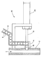
- the figure shows the essential components of the device, namely an application nozzle 2, through which the sealant is directed and dispensed in the direction of arrow 4, and a ball feed device 10.
- the ball feed device 10 has a feed channel 12 for feeding the balls 6 and an orifice tube 14 , which adjoins the feed channel 12 at a right angle and also opens laterally into the application nozzle 2 via an opening 16.
- a shock piston 18 is provided which can be driven by a pneumatic cylinder 20 and into the orifice tube 14 through the end facing away from the application nozzle 2 is movable.
- the fact that the feed channel 12 and the push piston 18 do not interfere with one another is due to the right-angled connection of the feed channel 12 to the orifice tube 14.
- the sealant can be passed through the application nozzle 2 by means of a pump and the balls 6 can be supplied by a suitable conveying device. However, the balls 6 can also be fed through the feed channel 12 with the aid of gravity, so that separate conveying devices can be dispensed with.
- the second element is then placed on and pressed against the first element until the balls embedded in the sealant come into contact with both elements. So that the balls can serve as spacers for fixing both elements at a defined distance from each other, they consist of solid material such as glass, plastic, ceramic or Stole.
- a pressure compensation tube can be inserted before the second pane is placed, to which a vacuum is applied after the second pane has been placed. This creates a negative pressure in the space between the two panes, which is sealed by the sealant that runs around the side edges of the panes, whereby both panes are pressed together and are thus fixed to one another.
- the pressure equalization tube is kept closed until the sealant has hardened. The vacuum is then released again. In this way, double glazing is obtained, the distance between the two panes being achieved by the balls in the sealant. Since the balls are enclosed by the sealant, a secure sealing of the space between the two panes is guaranteed at the same time.
Landscapes
- Engineering & Computer Science (AREA)
- Civil Engineering (AREA)
- Structural Engineering (AREA)
- Chemical & Material Sciences (AREA)
- Organic Chemistry (AREA)
- Joining Of Glass To Other Materials (AREA)
- Laminated Bodies (AREA)
- Die Bonding (AREA)
- Adhesives Or Adhesive Processes (AREA)
- Application Of Or Painting With Fluid Materials (AREA)
- Coating Apparatus (AREA)
Abstract
Description
Die Erfindung betrifft ein Verfahren und eine Vorrichtung zum Verkleben zweier im wesentlichen flächiger Elemente, bei welchem auf das erste Element ein hochviskoser Dichtstoff in einer mindestens dem gewünschten Abstand zu dem zweiten Element entsprechenden Dicke aufgetragen und das zweite Element über Abstandshalter auf das erste Element gelegt und angedrückt wird.The invention relates to a method and a device for gluing two essentially flat elements, in which a highly viscous sealant is applied to the first element in a thickness corresponding at least to the desired distance from the second element and the second element is placed on the first element via spacers and is pressed.
Ein derartiges Verfahren wird beispielsweise zur Herstellung von Doppelverglasungen verwendet, wobei die Elemente Glasscheiben sind und als Abstandshalter zur Fixierung beider Scheiben in einem definierten Abstand zueinander Stege aus Metall, vorzugsweise aus Aluminium, verwendet werden. Diese Metall-Stege werden entweder vor oder nach Auftrag des hochviskosen Dichtstoffes in einem separaten Arbeitsgang auf die erste Scheibe geklebt. In der Regel wird dabei der Dichtstoff auf die erste Scheibe vollständig entlang deren Seitenkanten mittels einer Auftragsdüse aufgetragen und der Metallsteg an der Innenseite des Dichtstoffes angeordnet, so daß nach Auflegen der zweiten Scheibe ein luftdichter Abschluß des Zwischenraums durch den umlaufenden Dichtstoff erfolgt.Such a method is used, for example, for the production of double glazing, the elements being glass panes and webs made of metal, preferably aluminum, used as spacers for fixing both panes at a defined distance from one another. These metal bars are glued to the first pane in a separate operation either before or after application of the highly viscous sealant. As a rule, the sealant is applied to the first pane completely along its side edges by means of an application nozzle and the metal web is arranged on the inside of the sealant, so that after the second pane has been placed on, the gap is sealed by the circumferential sealant.
Der Nachteil dieses Verfahrens besteht jedoch darin, daß für die Anordnung und Befestigung der als Abstandshalter dienenden Metall-Stege ein gesonderter Arbeitsschritt notwendig ist, der entweder vor oder nach Auftrag des Dichtstoffes durchgeführt wird, was einen erhöhten materiellen und personellen Aufwand erfordert. Hinzu kommt, daß die Metall-Stege in ihrer Lage und Länge dem Verlauf des Dichtstoffes und der Seitenkanten der Scheiben angepaßt werden müssen. Aus diesen Gründen ist auch eine Automatisierung dieses Verfahrens schwierig und aufwendig.The disadvantage of this method, however, is that a separate working step is necessary for the arrangement and fastening of the metal webs serving as spacers, which is carried out either before or after application of the sealant, which requires increased material and personnel expenditure. In addition, the position and length of the metal webs must be adapted to the course of the sealant and the side edges of the panes. For these reasons, automation of this process is difficult and complex.
In der DE-OS 21 30 773 ist ein Klebstoff beschrieben, der einen kalibrierten Füllstoff, vorzugsweise Glaskügelchen enthält. Ein solcher Klebstoff eignet sich nicht für die automatisierte Verarbeitung in einem Verfahren der vorstehend beschriebenen Art. Einerseits neigen Glaskügelchen mit Abmessungen, wie man sie als Abstandshalter für Doppelverglasungen benötigt, dazu, sich innerhalb der Klebstoffmasse abzusetzen. Vor allem aber gehen die Kügelchen, wenn sie willkürlich in dem Klebstoff verteilt sind, nicht gleichmäßig durch eine Auftragsdüse hindurch, deren Innendurchmesser nur wenig größer als ihr Außendurchmesser ist. Vielmehr besteht die Gefahr, daß die Kügelchen sich vor der Auftragsdüse ansammeln und diese verstopfen.DE-OS 21 30 773 describes an adhesive which contains a calibrated filler, preferably glass beads. Such an adhesive is not suitable for automated processing in a method of the type described above. On the one hand, glass spheres with dimensions as required as a spacer for double glazing tend to settle within the adhesive mass. Above all, however, if the beads are distributed arbitrarily in the adhesive, they do not pass uniformly through an application nozzle whose inside diameter is only slightly larger than its outside diameter. Rather, there is a risk that the beads will collect in front of the application nozzle and block it.
Der Erfindung liegt die Aufgabe zugrunde, das Verfahren der eingangs genannten Art dahingehend zu verbessern, daß die Abstandshalter nicht mehr in einem vom Auftrag des Dichtstoffes getrennten Arbeitsschritt zwischen den Elementen befestigt zu werden brauchen, wobei das verbesserte Verfahren insbesondere auch der Automatisierung zugänglich sein soll.The invention has for its object to improve the method of the type mentioned in such a way that the spacers no longer need to be attached between the elements in a separate work step from the application of the sealant, the improved method should also be accessible in particular to automation.
Diese Aufgabe wird durch das in Anspruch 1 bezeichnete Verfahren gelöst. Bevorzugte Ausführungsformen der Erfindung ergeben sich aus den Unteransprüchen.This object is achieved by the method described in claim 1. Preferred embodiments of the invention result from the subclaims.
Bei dem erfindungsgemäßen Verfahren werden als Abstandshalter Kugeln verwendet, die dem Dichtstoff vor dessen Auftrag in einer Auftragsdüse nacheinander zugegeben werden.In the method according to the invention, balls are used as spacers, which are added to the sealant in succession in an application nozzle before it is applied.
Dadurch ist es möglich, die Abstandshalter in einem einzigen Arbeitsgang zusammen mit dem Dichtstoff aufzutragen. Dadurch, daß die Kugeln dem Dichtstoff erst in der Auftragsdüse nacheinander zugegeben werden, ist gewährleistet, daß sie zusammen mit dem Dichtstoff in geordneter Weise aus der Auftragsdüse austreten. Die Gefahr einer Verstopfung der Auftragsdüse durch die Kugeln wird auf diese Weise vermieden. Nach Auftrag des die Kugeln enthaltenen Dichtstoffes auf das erste Element wird das zweite Element aufgelegt und in Richtung auf das erste Element angedrückt, bis die im Dichtstoff eingebetteten Kugeln mit beiden Elementen in Berührung kommen, so daß beide Elemente in einem durch den Durchmesser der Kugeln definierten Abstand fixiert werden.This makes it possible to apply the spacers together with the sealant in a single operation. The fact that the balls are added to the sealant one after the other in the application nozzle ensures that they emerge from the application nozzle together with the sealant in an orderly manner. The danger of one This prevents the balls from clogging the application nozzle. After application of the sealant containing the balls to the first element, the second element is placed and pressed in the direction of the first element until the balls embedded in the sealant come into contact with both elements, so that both elements are defined in one by the diameter of the balls Distance can be fixed.
Mit der erfindungsgemäßen Lösung kann insbesondere die Herstellung von Doppelverglasungen vereinfacht werden, da die Abstandshalter nicht mehr in einem gesonderten Arbeitsschritt, sondern gleichzeitig mit dem Auftrag des Dichtstoffes positioniert werden.The solution according to the invention can in particular be used to simplify the production of double glazing, since the spacers are no longer positioned in a separate work step, but at the same time as the sealant is applied.
Ferner eignet sich die Erfindung auch zur vereinfachten Anbringung von Glasscheiben an Automobilen. Zum Ausgleich von Fertigungstoleranzen, die insbesondere bei gewölbten Scheiben auftreten, werden nämlich die Automobilscheiben über Distanzhalter am Karosserieflansch befestigt und verklebt, was ebenfalls einen gesonderten Arbeitsschritt erfordert. Da dieser Arbeitsschritt beim erfindungsgemäßen Verfahren entfällt, kann somit die Anbringung von Glasscheiben an Automobilkarosserien wesentlich einfacher, schneller und kostengünstiger durchgeführt werden, was insbesondere bei einer automatisierten Produktion von Vorteil ist.Furthermore, the invention is also suitable for the simplified attachment of glass panes to automobiles. To compensate for manufacturing tolerances, which occur particularly in the case of curved windows, the automobile windows are attached and glued to the body flange using spacers, which likewise requires a separate work step. Since this step in the invention This eliminates the need for a process, which means that glass panes can be attached to car bodies much more easily, quickly and cost-effectively, which is particularly advantageous for automated production.
Vorzugsweise sollten die Kugeln aus festem Material wie Glas, Kunststoff, Keramik oder Stahl bestehen, da ein definierter Abstand zwischen beiden Scheiben gewährleistet sein soll.The balls should preferably be made of solid material such as glass, plastic, ceramic or steel, since a defined distance between the two disks should be ensured.
In einer bevorzugten Ausführungsform des Verfahrens sollten die Kugeln nacheinander in einem festen Zeitintervall in den Dichtstoff vor dessen Auftrag auf die erste Scheibe zugegeben werden, woraus sich nach Auftrag des Dichtstoffes automatisch ein bestimmter Abstand der in den Dichtstoff eingebetteten Kugeln zueinander ergibt.In a preferred embodiment of the method, the balls should be added to the sealant one after the other in a fixed time interval before it is applied to the first pane, which automatically results in a certain distance between the balls embedded in the sealant after application of the sealant.
Wenn bei Verwendung des erfindungsgemäßen Verfahrens zur Herstellung von Doppelverglasungen der Dichtstoff auf die erste Scheibe vollständig entlang deren Seitenkanten aufgetragen wird, sollte vorzugsweise nach Auftrag des Dichtstoffes auf die erste Scheibe und vor Auflegen der zweiten Scheibe ein Druckausgleichsröhrchen in den Dichtstoff eingelegt, nach Auflegen der zweiten Scheibe ein Unterdruck an das Druckausgleichsröhrchen angelegt und anschließend das Druckausgleichsröhrchen verschlossen und nach Aushärten des Dichtstoffes der Unterdruck zwischen den beiden Scheiben wieder abgebaut werden. Durch die Erzeugung eines Unterdrucks zwischen beiden Scheiben über ein Druckausgleichsröhrchen werden beide Scheiben während des Aushärtens des Dichtstoffes aneinander gedrückt und sind somit zueinander fixiert.If the sealant is applied to the first pane completely along the side edges when using the method for producing double glazing according to the invention, a pressure equalization tube should preferably be inserted into the sealant after the sealant has been applied to the first pane and before the second pane has been placed on it, after the second A vacuum is applied to the pressure compensation tube and then the pressure compensation tube is closed and after the sealant has hardened, the vacuum between the two discs is reduced again. By creating a negative pressure between the two panes via a pressure compensation tube, both panes are pressed against one another during the curing of the sealant and are thus fixed to one another.
Ferner ist es Aufgabe der Erfindung, eine Vorrichtung mit einer Auftragsdüse zum Zuleiten und Auftragen des Dichtstoffes dahingehend zu verbessern, daß mit ihr das erfindungsgemäße Verfahren durchführbar ist.Furthermore, it is an object of the invention to improve a device with an application nozzle for supplying and applying the sealant in such a way that the method according to the invention can be carried out with it.
Diese Aufgabe wird dadurch gelöst, daß eine Kugelzuführeinrichtung mit einem Zuführkanal zum Zuführen der Kugeln, mit einem Mündungsrohr, das sich in einem Winkel an den Zuführkanal anschließt und über eine Öffnung seitlich in die Auftragsdüse mündet, und mit einem Stoßkolben, der durch das von der Auftragsdüse abgewandten Ende in das Mündungsrohr hinein bewegbar ist, vorgesehen ist, wobei die lichte Weite der Auftragsdüse, des Zuführkanals und des Mündungsrohres größer und der Außendurchmesser des Stoßkolbens kleiner als der Durchmesser der Kugeln sind.This object is achieved in that a ball feed device with a feed channel for feeding the balls, with a muzzle tube which adjoins the feed channel at an angle and opens laterally into the application nozzle via an opening, and with a pushing piston which is guided by the End facing away from the application nozzle can be moved into the orifice tube, is provided, the clear width of the application nozzle, the feed channel and the orifice tube being larger and the outside diameter of the impact piston being smaller than the diameter of the balls.
Demnach wird eine herkömmliche Auftragsdüse durch die der Dichtstoff geleitet und aufgetragen wird, erfindungsgemäß um die Kugelzuführeinrichtung erweitert, durch die die Kugeln in die Auftragsdüse geleitet und somit in den dort befindlichen Dichtstoff vor dessen Abgabe zugegeben werden. Dabei werden die Kugeln über den Zuführkanal in das sich anschließende Mündungsrohr geleitet und von dort mit dem Stoßkolben in die Auftragsdüse gestoßen. Daß sich der Stoßkolben und der in das Mündungsrohr mündende Zuführkanal nicht gegenseitig behindern, wird dadurch erreicht, daß der Zuführkanal in einem Winkel mit dem Mündungsrohr verbunden ist. Somit werden die Kugeln vom Zuführkanal seitlich in das Mündungsrohr geleitet, bevor sie mit dem Stoßkolben durch das Mündungsrohr in die Auftragsdüse gestoßen werden.Accordingly, a conventional application nozzle through which the sealant is guided and applied is expanded according to the invention by the ball feed device, through which the balls are guided into the application nozzle and are thus added to the sealant located there before it is dispensed. The balls are fed through the feed channel into the adjoining outlet pipe and from there they are pushed into the application nozzle with the pushing piston. The fact that the impact piston and the feed channel opening into the mouth pipe do not interfere with one another is achieved in that the feed channel is connected at an angle to the mouth pipe. Thus, the balls are guided laterally into the orifice tube from the feed channel before they are pushed with the impact piston through the orifice tube into the application nozzle.
Besonders vorteilhaft eignet sich die erfindungsgemäße Vorrichtung zur automatisierten Herstellung von Doppelverglasungen (Isolierglasscheiben) sowie zur automatisierten Befestigung von Glasscheiben an Fahrzeugkarosserien. Das Durchleiten und Abgeben des Dichtstoffes durch die Auftragsdüse, die Zuführung der Kugeln und die Bewegung des Stoßkolbens können in einfacher Weise durch geeignete Einrichtungen mechanisiert werden, wobei die Zuführung der Kugeln durch den Zuführkanal auch mit Hilfe der Schwerkraft erfolgen kann. Mit einer Steuereinrichtung kann dabei der Arbeitsablauf der erfindungsgemäßen Vorrichtung in einfacher Weise gesteuert werden.The device according to the invention is particularly advantageously suitable for the automated production of double glazing (insulating glass panes) and for the automated fastening of glass panes to vehicle bodies. The Passing and dispensing the sealant through the application nozzle, the supply of the balls and the movement of the impact piston can be mechanized in a simple manner by suitable devices, wherein the supply of the balls through the supply channel can also take place with the aid of gravity. The workflow of the device according to the invention can be controlled in a simple manner with a control device.
In einer vorteilhaften Weiterbildung schließt sich das Mündungsrohr winklig an den Zuführkanal an und mündet ebenfalls winklig in die Auftragsdüse. Auf diese Weise erhält man eine besonders kompakte Anordnung, da der Zuführkanal zumindest im Verbindungsbereich mit dem Mündungsrohr in derselben Ebene wie die Auftragsdüse liegt.In an advantageous development, the mouth pipe connects at an angle to the feed channel and also opens at an angle into the application nozzle. In this way, a particularly compact arrangement is obtained since the feed channel lies at least in the connection area with the outlet pipe in the same plane as the application nozzle.
Vorzugsweise sollte der Stoßkolben von einem Pneumatik-Zylinder antreibbar sein, da ein derartiger Antrieb einen sehr einfachen Aufbau ergibt.The impact piston should preferably be drivable by a pneumatic cylinder, since such a drive results in a very simple construction.
Die Erfindung wird nachstehend anhand der einzigen Zeichnung erläutert, welche die dargestellte Ausführungsform der Vorrichtung im Schnitt zeigt.The invention is explained below with reference to the single drawing, which shows the illustrated embodiment of the device in section.
Die Figur zeigt die wesentlichen Komponenten der Vorrichtung, nämlich eine Auftragsdüse 2, durch die in Richtung des Pfeils 4 der Dichtstoff geleitet und abgegeben wird, und eine Kugelzuführeinrichtung 10. Die Kugelzuführeinrichtung 10 weist einen Zuführkanal 12 zum Zuführen der Kugeln 6 und ein Mündungsrohr 14 auf, das sich im rechten Winkel an den Zuführkanal 12 anschließt und ebenfalls im rechten Winkel über eine Öffnung 16 seitlich in die Auftragsdüse 2 mündet. Ferner ist ein Stoßkolben 18 vorgesehen, der von einem Pneumatik-Zylinder 20 antreibbar und durch das von der Auftragsdüse 2 abgewandte Ende in das Mündungsrohr 14 bewegbar ist. Daß sich der Zuführkanal 12 und der Stoßkolben 18 gegenseitig nicht behindern, liegt an dem rechtwinkligen Anschluß des Zuführkanals 12 an das Mündungsrohr 14.The figure shows the essential components of the device, namely an
Das Durchleiten des Dichtstoffes durch die Auftragsdüse 2 kann mit Hilfe einer Pumpe und die Zuführung der Kugeln 6 durch eine geeignete Fördereinrichtung erfolgen. Ebenfalls kann aber auch die Zuführung der Kugeln 6 durch den Zuführkanal 12 mit Hilfe der Schwerkraft erfolgen, so daß auf gesonderte Fördereinrichtungen verzichtet werden kann.The sealant can be passed through the
Im folgenden soll das Verfahren zum Verkleben zweier im wesentlichen flächiger Elemente mit Hilfe der beschriebenen Vorrichtung erläutert werden:
Während durch die Auftragsdüse 2 der hochviskose Dichtstoff in Richtung des Pfeils 4 geleitet bzw. gepumpt wird, werden die Kugeln 6 nacheinander mit dem Stoßkolben 18 durch das Mündungsrohr 14 und die Öffnung 16 von der Seite in die Auftragsdüse 2 gestoßen und somit in den dort befindlichen Dichtstoff gegeben. Anschließend wird der Dichtstoff mit den darin eingebetteten Kugeln 6 aus der Auftragsdüse 2 abgegeben und auf das erste Element aufgetragen. Der Stoßkolben 18 wird nur in bestimmten Zeitintervallen betätigt, damit die Kugeln 6 in einem bestimmten zeitlichen Abstand zueinander in den Dichtstoff gegeben und dadurch nach dessen Auftrag auf dem Element in einem bestimmten räumlichen Abstand zueinander positioniert werden.The method for gluing two essentially flat elements with the aid of the described device will be explained below:
While the highly viscous sealant is passed or pumped through the
Anschließend wird das zweite Element aufgelegt und gegen das erste Element gedrückt, bis die im Dichtstoff eingebetteten Kugeln mit beiden Elementen in Berührung kommen. Damit die Kugeln als Abstandshalter zur Fixierung beider Elemente in einem definierten Abstand zueinander dienen können, bestehen sie aus festem Material wie Glas, Kunststoff, Keramik oder Stahl.The second element is then placed on and pressed against the first element until the balls embedded in the sealant come into contact with both elements. So that the balls can serve as spacers for fixing both elements at a defined distance from each other, they consist of solid material such as glass, plastic, ceramic or Stole.
Wenn bei Verwendung des erfindungsgemäßen Verfahrens zur Herstellung von Doppelverglasungen der Dichtstoff auf die erste Scheibe vollständig entlang deren Seitenkanten aufgetragen wird, kann vor Auflegen der zweiten Scheibe ein Druckausgleichsröhrchen eingelegt werden, an das nach Auflegen der zweiten Scheibe ein Unterdruck angelegt wird. Dadurch entsteht in dem Zwischenraum zwischen beiden Scheiben, der von dem entlang der Seitenkanten der Scheiben streifenförmig umlaufenden Dichtstoff abgedichtet ist, ein Unterdruck, wodurch beide Scheiben aneinandergedrückt werden und somit zueinander fixiert sind. Dabei wird das Druckausgleichsröhrchen so lange geschlossen gehalten, bis der Dichtstoff ausgehärtet ist. Anschließend wird der Unterdruck wieder abgebaut. Auf diese Weise erhält man eine Doppelverglasung, wobei der Abstand beider Scheiben zueinander durch die im Dichtstoff liegenden Kugeln erreicht wird. Da die Kugeln vom Dichtstoff umschlossen sind, wird gleichzeitig eine sichere Abdichtung des Zwischenraums zwischen beiden Scheiben nach außen gewährleistet.If, when using the method according to the invention for the production of double glazing, the sealant is applied completely to the first pane along the side edges thereof, a pressure compensation tube can be inserted before the second pane is placed, to which a vacuum is applied after the second pane has been placed. This creates a negative pressure in the space between the two panes, which is sealed by the sealant that runs around the side edges of the panes, whereby both panes are pressed together and are thus fixed to one another. The pressure equalization tube is kept closed until the sealant has hardened. The vacuum is then released again. In this way, double glazing is obtained, the distance between the two panes being achieved by the balls in the sealant. Since the balls are enclosed by the sealant, a secure sealing of the space between the two panes is guaranteed at the same time.
Claims (8)
- A process for adhesively bonding two substantially planar elements, wherein a highly viscous sealant which contains balls as spacers is applied to the first element in a thickness which corresponds at least to the desired interval from the second element, and the second element is applied to and pressed against the first element, characterised in that the balls are added consecutively to the sealant prior to its application in an application nozzle.
- A process as claimed in Claim 1, characterised in that the balls consist of solid material, such as glass, synthetic resin, ceramic or steel.
- A process as claimed in one of Claims 1 or 2, characterised in that the elements are sheets, in particular glass panes.
- A process as claimed in Claims 1, 2 or 3, characterised in that the balls are added at fixed intervals of time.
- A process as claimed in Claim 4, wherein the sealant is applied to the first sheet continuously along its side edges, characterised in that a pressure-compensating pipe is introduced into the sealant following the application of the sealant to the first sheet and prior to the application of the second sheet, a vacuum is connected to the pressure-compensating pipe following the application of the second sheet, whereupon the pressure-compensating pipe is closed and, following the hardening of the sealant, the vacuum between the two sheets is broken down again.
- A device for the implementation of the process as claimed in one of Claims 1 to 5, with an application nozzle (2) for the conveyance and application of the sealant (4), characterised by a ball supply device (10)- comprising a supply channel (12) for supplying the balls (6),- comprising an outlet pipe (14) which adjoins the supply channel (12) at an angle and, via an opening (16), leads laterally into the application nozzle (12) and- comprising a ram (18) which, by the end facing away from the application nozzle (2), can be moved into the outlet pipe (14),- wherein the internal width of the application nozzle (2), the supply channel (12) and the outlet pipe (14) is greater than, and the outer diameter of the ram (18) is smaller than, the diameter of the balls (6).
- A device as claimed in Claim 5, characterised in that the outlet pipe (14) adjoins the supply channel (12) at an angle and leads into the application nozzle (2) likewise at an angle.
- A device as claimed in Claim 5 or 6, characterised in that the ram (18) can be driven by a pneumatic cylinder (20).
Priority Applications (1)
| Application Number | Priority Date | Filing Date | Title |
|---|---|---|---|
| AT88109032T ATE79390T1 (en) | 1987-06-12 | 1988-06-07 | METHOD AND DEVICE FOR BONDING TWO ESSENTIALLY FLAT ELEMENTS. |
Applications Claiming Priority (2)
| Application Number | Priority Date | Filing Date | Title |
|---|---|---|---|
| DE19873719599 DE3719599A1 (en) | 1987-06-12 | 1987-06-12 | METHOD AND DEVICE FOR BONDING TWO ESSENTIAL AREAS OF ELEMENTS |
| DE3719599 | 1987-06-12 |
Publications (3)
| Publication Number | Publication Date |
|---|---|
| EP0294754A2 EP0294754A2 (en) | 1988-12-14 |
| EP0294754A3 EP0294754A3 (en) | 1990-05-30 |
| EP0294754B1 true EP0294754B1 (en) | 1992-08-12 |
Family
ID=6329538
Family Applications (1)
| Application Number | Title | Priority Date | Filing Date |
|---|---|---|---|
| EP88109032A Expired - Lifetime EP0294754B1 (en) | 1987-06-12 | 1988-06-07 | Process and apparatus for bonding two substantially flat elements |
Country Status (5)
| Country | Link |
|---|---|
| US (2) | US4865672A (en) |
| EP (1) | EP0294754B1 (en) |
| JP (1) | JPS6456780A (en) |
| AT (1) | ATE79390T1 (en) |
| DE (2) | DE3719599A1 (en) |
Families Citing this family (17)
| Publication number | Priority date | Publication date | Assignee | Title |
|---|---|---|---|---|
| US5474629A (en) * | 1990-12-15 | 1995-12-12 | Semiconductor Energy Laboratory Co., Ltd. | Method for manufacturing a liquid crystal device |
| DE19533855C1 (en) * | 1995-09-13 | 1997-04-24 | Lenhardt Maschinenbau | Method for assembling insulating glass plates |
| FR2787133B1 (en) * | 1998-12-10 | 2001-01-26 | Saint Gobain Vitrage | VACUUM INSULATING GLAZING AND METHOD FOR PRODUCING THE SAME |
| US6291036B1 (en) * | 1999-05-03 | 2001-09-18 | Guardian Industries Corporation | Vacuum IG window unit with spacers in seal |
| US6336984B1 (en) | 1999-09-24 | 2002-01-08 | Guardian Industries Corporation | Vacuum IG window unit with peripheral seal at least partially diffused at temper |
| US7126450B2 (en) * | 1999-06-21 | 2006-10-24 | Access Business Group International Llc | Inductively powered apparatus |
| US6365242B1 (en) | 1999-07-07 | 2002-04-02 | Guardian Industries Corp. | Peripheral seal for vacuum IG window unit |
| US6558494B1 (en) | 1999-09-24 | 2003-05-06 | Guardian Industries Corp. | Vacuum IG window unit with edge seal at least partially diffused at temper and completed via microwave curing, and corresponding method of making the same |
| US6444281B1 (en) * | 1999-10-13 | 2002-09-03 | Guardian Industries Corp. | Vacuum IG window unit with spacers between first and second edge seals |
| US6701749B2 (en) | 2000-09-27 | 2004-03-09 | Guardian Industries Corp. | Vacuum IG window unit with edge seal at least partially diffused at temper and completed via microwave curing, and corresponding method of making the same |
| DE102005023102A1 (en) * | 2005-05-13 | 2006-11-16 | Unaxis Balzers Ag | Structured gluing method e.g. for surfaces, involves making surface of body available, on which structured adhesive layer is to be applied with filter and blade provided |
| US10012019B2 (en) | 2013-12-31 | 2018-07-03 | Guardian Glass, LLC | Vacuum insulating glass (VIG) unit with metallic peripheral edge seal and/or methods of making the same |
| US10280680B2 (en) | 2013-12-31 | 2019-05-07 | Guardian Glass, LLC | Vacuum insulating glass (VIG) unit with pump-out port sealed using metal solder seal, and/or method of making the same |
| US9784027B2 (en) | 2013-12-31 | 2017-10-10 | Guardian Glass, LLC | Vacuum insulating glass (VIG) unit with metallic peripheral edge seal and/or methods of making the same |
| US10145005B2 (en) | 2015-08-19 | 2018-12-04 | Guardian Glass, LLC | Techniques for low temperature direct graphene growth on glass |
| CN106076515B (en) * | 2016-08-26 | 2017-12-15 | 中冶北方(大连)工程技术有限公司 | Gear tooth-type ball feeder |
| JP6917580B2 (en) * | 2017-05-31 | 2021-08-11 | パナソニックIpマネジメント株式会社 | Pillar mounting method and glass panel unit manufacturing method |
Family Cites Families (14)
| Publication number | Priority date | Publication date | Assignee | Title |
|---|---|---|---|---|
| US2821890A (en) * | 1954-07-08 | 1958-02-04 | Wald Ind Inc | Apparatus and method for marking a surface |
| US3101761A (en) * | 1959-02-17 | 1963-08-27 | Gen Foods Corp | Apparatus for forming food portions of uniform weight by volumetric measurement |
| DE2130773A1 (en) * | 1970-07-02 | 1972-04-13 | Iskra Zd Za Avtomatizacijo V Z | Adhesive for gluing with a precisely determined distance |
| JPS4930259B1 (en) * | 1970-09-28 | 1974-08-12 | ||
| JPS5037707B1 (en) * | 1971-01-18 | 1975-12-04 | ||
| JPS526097B2 (en) * | 1972-03-14 | 1977-02-18 | ||
| US3892171A (en) * | 1973-09-07 | 1975-07-01 | Clifford E Fitch | Apparatus for making pizzas or the like |
| JPS527021A (en) * | 1975-07-07 | 1977-01-19 | Nippon Kokan Kk <Nkk> | Anticorrosive method of tee joint in piping works |
| FR2479083A1 (en) * | 1980-03-27 | 1981-10-02 | Europ Accumulateurs | AUTOMATIC BUS POWER SUPPLY DEVICE FOR A COVER MOLDING PRESS FOR BATTERIES OF ACCUMULATORS |
| JPS5774114A (en) * | 1980-10-29 | 1982-05-10 | Hitachi Ltd | Connecting method of laminated board |
| DE3150844A1 (en) * | 1981-12-22 | 1983-06-30 | Max Planck Gesellschaft zur Förderung der Wissenschaften e.V., 3400 Göttingen | Process and adhesive for bonding components |
| US4640583A (en) * | 1983-07-22 | 1987-02-03 | Kabushiki Kaisha Seiko Epson | Display panel having an inner and an outer seal and process for the production thereof |
| GB2149719A (en) * | 1983-11-14 | 1985-06-19 | American Standard Inc | A method of bonding a laminated assembly |
| JPS6162575A (en) * | 1984-09-03 | 1986-03-31 | Toyo Eng Corp | Method of bonding using core for space |
-
1987
- 1987-06-12 DE DE19873719599 patent/DE3719599A1/en active Granted
-
1988
- 1988-06-07 AT AT88109032T patent/ATE79390T1/en not_active IP Right Cessation
- 1988-06-07 EP EP88109032A patent/EP0294754B1/en not_active Expired - Lifetime
- 1988-06-07 DE DE8888109032T patent/DE3873630D1/en not_active Expired - Fee Related
- 1988-06-07 US US07/203,185 patent/US4865672A/en not_active Expired - Fee Related
- 1988-06-10 JP JP63141866A patent/JPS6456780A/en active Pending
-
1989
- 1989-06-30 US US07/373,558 patent/US4997354A/en not_active Expired - Fee Related
Also Published As
| Publication number | Publication date |
|---|---|
| US4865672A (en) | 1989-09-12 |
| JPS6456780A (en) | 1989-03-03 |
| DE3873630D1 (en) | 1992-09-17 |
| US4997354A (en) | 1991-03-05 |
| DE3719599C2 (en) | 1989-05-03 |
| DE3719599A1 (en) | 1988-12-22 |
| EP0294754A3 (en) | 1990-05-30 |
| EP0294754A2 (en) | 1988-12-14 |
| ATE79390T1 (en) | 1992-08-15 |
Similar Documents
| Publication | Publication Date | Title |
|---|---|---|
| EP0294754B1 (en) | Process and apparatus for bonding two substantially flat elements | |
| DE4433749C2 (en) | Method and device for applying a plastic spacer to a glass sheet | |
| DE69317303T3 (en) | SELF-PUNCHED RIVETS | |
| EP1373000A1 (en) | Method and device for attaching support sections for rubber seals to automobile body parts and corresponding support section | |
| DE10254573A1 (en) | Modular roof for motor vehicle has a camber provided both on flange of roof aperture in region of side members and also on modular roof, with roof camber in vehicle's longitudinal direction less than camber of flange | |
| EP0645290A1 (en) | Power booster case, especially for motor vehicle braking systems, and method for assembling or putting together such power booster case | |
| WO2019185194A1 (en) | Method and device for cutting off an extrudate | |
| DE3246626A1 (en) | METHOD AND DEVICE FOR PRODUCING A GUIDE RAIL | |
| WO2008028970A1 (en) | Device for dispensing viscous or pasty matter | |
| DE69702540T2 (en) | DEVICE AND METHOD FOR STRAIGHTING METALLIC AND PLATFORMED PARTS | |
| DE102012019084B4 (en) | Method and device for producing an adhesive bond | |
| DE102018202850A1 (en) | Application device for applying a sealing profile and method | |
| EP0369181A2 (en) | Process and nozzle for vitrifying the edges of thin work pieces | |
| DE102014007553B4 (en) | Method for connecting at least two components and device for carrying out such a method | |
| DE102011050751A1 (en) | Robot-guided applicator device for attaching circulating sealing profile at door of motor car, has front and rear rollers whose shells are brought into contact with sealing profile, where rollers are coupled with each other by driving belt | |
| DE102018201392B4 (en) | Device for filling wells with a viscous material | |
| DE2632337A1 (en) | DEVICE FOR COATING THE SIDE OF A SPACER FRAME FOR INSULATING GLASS PANELS WITH A DURABLE ADHESIVE LAYER | |
| WO1991006740A1 (en) | Process for combining two sheets of glass to form an insulating pane and device for implementing it | |
| DE102005049051B3 (en) | Coating a component with an adhesive or sealant, for bonding to another component, uses micro-spheres containing the coating as spacer bodies to be compressed when the components are pressed together | |
| EP3459771B1 (en) | Pressure bar for holding and pressing a seal profile | |
| DE10115091A1 (en) | Method and device for attaching support sections for rubber sealing profile to body of vehicle | |
| WO2008074550A1 (en) | Tubular plate bar for a windscreen wiper system | |
| DE4411433A1 (en) | Procedure for fitting profiled flexible tubing onto inner flange of cut=out | |
| DE19816824A1 (en) | Robot adhesive/sealant applicator for glass panes in motor vehicles | |
| EP0150375B1 (en) | Process for manufacturing a welder boiler and boiler produced by this process |
Legal Events
| Date | Code | Title | Description |
|---|---|---|---|
| PUAI | Public reference made under article 153(3) epc to a published international application that has entered the european phase |
Free format text: ORIGINAL CODE: 0009012 |
|
| AK | Designated contracting states |
Kind code of ref document: A2 Designated state(s): AT BE CH DE ES FR GB GR IT LI LU NL SE |
|
| PUAL | Search report despatched |
Free format text: ORIGINAL CODE: 0009013 |
|
| AK | Designated contracting states |
Kind code of ref document: A3 Designated state(s): AT BE CH DE ES FR GB GR IT LI LU NL SE |
|
| 17P | Request for examination filed |
Effective date: 19900718 |
|
| 17Q | First examination report despatched |
Effective date: 19910813 |
|
| GRAA | (expected) grant |
Free format text: ORIGINAL CODE: 0009210 |
|
| AK | Designated contracting states |
Kind code of ref document: B1 Designated state(s): AT BE CH DE ES FR GB GR IT LI LU NL SE |
|
| PG25 | Lapsed in a contracting state [announced via postgrant information from national office to epo] |
Ref country code: IT Free format text: LAPSE BECAUSE OF FAILURE TO SUBMIT A TRANSLATION OF THE DESCRIPTION OR TO PAY THE FEE WITHIN THE PRE;WARNING: LAPSES OF ITALIAN PATENTS WITH EFFECTIVE DATE BEFORE 2007 MAY HAVE OCCURRED AT ANY TIME BEFORE 2007. THE CORRECT EFFECTIVE DATE MAY BE DIFFERENT FROM THE ONE RECORDED.SCRIBED TIME-LIMIT Effective date: 19920812 Ref country code: GB Effective date: 19920812 Ref country code: NL Effective date: 19920812 Ref country code: SE Free format text: THE PATENT HAS BEEN ANNULLED BY A DECISION OF A NATIONAL AUTHORITY Effective date: 19920812 Ref country code: FR Effective date: 19920812 Ref country code: ES Free format text: THE PATENT HAS BEEN ANNULLED BY A DECISION OF A NATIONAL AUTHORITY Effective date: 19920812 Ref country code: BE Effective date: 19920812 Ref country code: GR Free format text: LAPSE BECAUSE OF FAILURE TO SUBMIT A TRANSLATION OF THE DESCRIPTION OR TO PAY THE FEE WITHIN THE PRESCRIBED TIME-LIMIT Effective date: 19920812 |
|
| REF | Corresponds to: |
Ref document number: 79390 Country of ref document: AT Date of ref document: 19920815 Kind code of ref document: T |
|
| REF | Corresponds to: |
Ref document number: 3873630 Country of ref document: DE Date of ref document: 19920917 |
|
| EN | Fr: translation not filed | ||
| NLV1 | Nl: lapsed or annulled due to failure to fulfill the requirements of art. 29p and 29m of the patents act | ||
| GBV | Gb: ep patent (uk) treated as always having been void in accordance with gb section 77(7)/1977 [no translation filed] |
Effective date: 19920812 |
|
| PG25 | Lapsed in a contracting state [announced via postgrant information from national office to epo] |
Ref country code: AT Effective date: 19930607 |
|
| PLBE | No opposition filed within time limit |
Free format text: ORIGINAL CODE: 0009261 |
|
| STAA | Information on the status of an ep patent application or granted ep patent |
Free format text: STATUS: NO OPPOSITION FILED WITHIN TIME LIMIT |
|
| PG25 | Lapsed in a contracting state [announced via postgrant information from national office to epo] |
Ref country code: LI Effective date: 19930630 Ref country code: CH Effective date: 19930630 Ref country code: LU Free format text: LAPSE BECAUSE OF NON-PAYMENT OF DUE FEES Effective date: 19930630 |
|
| 26N | No opposition filed | ||
| REG | Reference to a national code |
Ref country code: CH Ref legal event code: PL |
|
| PG25 | Lapsed in a contracting state [announced via postgrant information from national office to epo] |
Ref country code: DE Effective date: 19940301 |