EP0294689B1 - Hot film type air flow meter - Google Patents
Hot film type air flow meter Download PDFInfo
- Publication number
- EP0294689B1 EP0294689B1 EP88108679A EP88108679A EP0294689B1 EP 0294689 B1 EP0294689 B1 EP 0294689B1 EP 88108679 A EP88108679 A EP 88108679A EP 88108679 A EP88108679 A EP 88108679A EP 0294689 B1 EP0294689 B1 EP 0294689B1
- Authority
- EP
- European Patent Office
- Prior art keywords
- film type
- thin film
- air flow
- element forming
- forming thin
- Prior art date
- Legal status (The legal status is an assumption and is not a legal conclusion. Google has not performed a legal analysis and makes no representation as to the accuracy of the status listed.)
- Expired - Lifetime
Links
- 239000010409 thin film Substances 0.000 claims description 103
- 239000004020 conductor Substances 0.000 claims description 99
- 239000010408 film Substances 0.000 claims description 66
- 239000000758 substrate Substances 0.000 claims description 27
- BASFCYQUMIYNBI-UHFFFAOYSA-N platinum Chemical compound [Pt] BASFCYQUMIYNBI-UHFFFAOYSA-N 0.000 claims description 25
- PNEYBMLMFCGWSK-UHFFFAOYSA-N aluminium oxide Inorganic materials [O-2].[O-2].[O-2].[Al+3].[Al+3] PNEYBMLMFCGWSK-UHFFFAOYSA-N 0.000 claims description 17
- 229910052697 platinum Inorganic materials 0.000 claims description 12
- 230000008020 evaporation Effects 0.000 claims description 11
- 238000001704 evaporation Methods 0.000 claims description 11
- 239000000463 material Substances 0.000 claims description 10
- 229920003002 synthetic resin Polymers 0.000 claims 1
- 239000000057 synthetic resin Substances 0.000 claims 1
- 239000011347 resin Substances 0.000 description 9
- 229920005989 resin Polymers 0.000 description 9
- 230000000717 retained effect Effects 0.000 description 4
- 238000002485 combustion reaction Methods 0.000 description 3
- 238000010586 diagram Methods 0.000 description 3
- 239000011521 glass Substances 0.000 description 3
- 238000004519 manufacturing process Methods 0.000 description 3
- 239000004033 plastic Substances 0.000 description 3
- 229920003023 plastic Polymers 0.000 description 3
- 239000000126 substance Substances 0.000 description 3
- 230000005684 electric field Effects 0.000 description 2
- 230000007257 malfunction Effects 0.000 description 2
- -1 polybutylene terephthalate Polymers 0.000 description 2
- 229920001707 polybutylene terephthalate Polymers 0.000 description 2
- 239000004743 Polypropylene Substances 0.000 description 1
- UCKMPCXJQFINFW-UHFFFAOYSA-N Sulphide Chemical compound [S-2] UCKMPCXJQFINFW-UHFFFAOYSA-N 0.000 description 1
- 239000007767 bonding agent Substances 0.000 description 1
- 239000003990 capacitor Substances 0.000 description 1
- 238000010276 construction Methods 0.000 description 1
- 230000000694 effects Effects 0.000 description 1
- 229910052741 iridium Inorganic materials 0.000 description 1
- WABPQHHGFIMREM-UHFFFAOYSA-N lead(0) Chemical compound [Pb] WABPQHHGFIMREM-UHFFFAOYSA-N 0.000 description 1
- 229920001155 polypropylene Polymers 0.000 description 1
Images

Classifications
-
- G—PHYSICS
- G01—MEASURING; TESTING
- G01F—MEASURING VOLUME, VOLUME FLOW, MASS FLOW OR LIQUID LEVEL; METERING BY VOLUME
- G01F1/00—Measuring the volume flow or mass flow of fluid or fluent solid material wherein the fluid passes through a meter in a continuous flow
- G01F1/68—Measuring the volume flow or mass flow of fluid or fluent solid material wherein the fluid passes through a meter in a continuous flow by using thermal effects
- G01F1/684—Structural arrangements; Mounting of elements, e.g. in relation to fluid flow
-
- G—PHYSICS
- G01—MEASURING; TESTING
- G01F—MEASURING VOLUME, VOLUME FLOW, MASS FLOW OR LIQUID LEVEL; METERING BY VOLUME
- G01F1/00—Measuring the volume flow or mass flow of fluid or fluent solid material wherein the fluid passes through a meter in a continuous flow
- G01F1/68—Measuring the volume flow or mass flow of fluid or fluent solid material wherein the fluid passes through a meter in a continuous flow by using thermal effects
- G01F1/684—Structural arrangements; Mounting of elements, e.g. in relation to fluid flow
- G01F1/688—Structural arrangements; Mounting of elements, e.g. in relation to fluid flow using a particular type of heating, cooling or sensing element
- G01F1/69—Structural arrangements; Mounting of elements, e.g. in relation to fluid flow using a particular type of heating, cooling or sensing element of resistive type
- G01F1/692—Thin-film arrangements
-
- G—PHYSICS
- G01—MEASURING; TESTING
- G01F—MEASURING VOLUME, VOLUME FLOW, MASS FLOW OR LIQUID LEVEL; METERING BY VOLUME
- G01F1/00—Measuring the volume flow or mass flow of fluid or fluent solid material wherein the fluid passes through a meter in a continuous flow
- G01F1/68—Measuring the volume flow or mass flow of fluid or fluent solid material wherein the fluid passes through a meter in a continuous flow by using thermal effects
- G01F1/696—Circuits therefor, e.g. constant-current flow meters
- G01F1/698—Feedback or rebalancing circuits, e.g. self heated constant temperature flowmeters
Definitions
- the present invention relates to a hot film type air flow meter using a thin film type exothermic resistance element as an air flow rate detecting resistance element and a thin film type air flow temperature sensing resistance element, and more particularly to a hot film type air flow meter having a resin material flow meter main body suitably used as a suction air flow meter in an internal combustion engine for an automobile.
- a suction air flow meter has been used extensively for controlling a gasoline engine for an automobile. Recently, a hot film type air flow meter has been used as this suction air flow meter in the gasoline for the automobile.
- This hot film type air flow meter has a thin film type an air flow rate detecting resistance element as a main resistance element and also has a thin film type temperature sensing or temperature compensating resistance element as an auxiliary resistance element.
- Such a hot film type air flow meter is disclosed in, for example, Japanese Patent Laid-Open No. 236029/1985.
- the hot film type air flow meter having a thin film type resistance element such as an air flow rate detecting resistance element etc. enables the reliability to be improved and the manufacturing cost of the air flow rate detecting resistance elements and temperature sensing resistance elements as the hot film type resistance element to be reduced, respectively, and users in this technical field expect much from this hot film type air flow meter.
- a flow meter main body of the hot film type air flow meter in an engine for the automobile has been made of a resin material or plastics. This gives rise to a big problem concerning the radio interference resistance of the above-mentioned prior art hot film type air flow meter.
- the hot film type air flow meter for use in a suction air flow meter in an engine for an automobile comprises a thin film type exothermic resistance element or resistor, for use of detecting the air flow rate of an air current or suction air, a thin film type temperature sensing resistance element or resistor for use of sensing the temperature of the suction air, a control module with an air flow state detecting circuit mounted thereon, and a flow meter main body constituting a part of a suction air passage in an engine.
- the exothermic resistance element and the temperature sensing resistance element are assembled unitary with the control module. Since the control module is fixed to the flow meter main body which is molded integrally out a resin material. The exothermic resistance element and the temperature sensing resistance element are retained in the respective predetermined position in the suction air passage. The exothermic resistance element and the temperature sensing resistance element are projected greatly from the control module and retained in this state.
- the flow meter main body has been molded out of a resin material or plastics. Consequently, for example, when the wireless equipment is provided as an electric instrument in the automobile, the exothermic resistance element and the temperature sensing resistance element become exposed to a considerably high frequency electric field.
- the exothermic resistance element and the temperature sensing resistance element work as antennas, so that an electromagnetic waves or a considerably high frequency noise voltage is introduced into the control module to cause the radio interference resistance of the hot film type air flow meter to decrease.
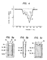
- radio interference resistance of the conventional hot film type air flow meter has the characteristics curve a shown in Fig. 4, in which the radio interference resistance lowers greatly in the vicinity of, especially, the value of 470 MHz of frequency.
- a hot film type air flow meter provided with a shield structure for the control module so as to improve the radio interference resistance thereof has also been proposed.
- the number of nodes between a shield base being disposed in the control module and the flow meter main body in the control module to ground is increased from one, which is the number referring to the conventional case of the hot film type air flow meter, to two to three.
- the radio interference resistance characteristics of the node-increased hot film type air flow meter is as shown by curve b in Fig. 4.
- the radio interference resistance is improved to only a small extent. It is understood that it is difficult to obtain a satisfactory countermeasure by taking only such a step.
- WO 87/00917 discloses a mass airflow sensor wherein said problem of noise interference is solved with a housing that protects the electronic components which are part of the sensor.
- An object of the present invention is to provide a hot film type air flow meter wherein a sufficiently high radio interference resistance can be obtained easily.
- Another object of the present invention is to provide a hot film type air flow meter wherein the malfunction of a high radio interference resistance can be easily prevented even when a flow meter main body of the hot film type air flow meter is made of a resin material.
- the present invention provides therefore a hot film type air flow meter having a thin film type conductor, which is formed on one surface of a dielectric substrate member, as an air flow rate detecting resistance element, and an element for shielding the air flow meter from electromagnetic waves, characterized in that as said shielding element a shield electrode element forming thin film type conductor is provided in a vicinity of said air flow rate detecting resistance element forming thin film type conductor, and said shield electrode element forming thin film type conductor is connected to a portion having the lowest potential within the conductors, whereby a guidance of high frequency radio waves to said air flow rate detecting resistance element is prevented from arising.
- this shield electrode element forming thin film type conductor is maintained at the lowest potential such as ground or a common potential, this electro-static capacity functions as a bypass condenser, and the guidance of high frequency radio waves, which has entered the shield electrode element forming thin film type conductor, to the resistance element can be effectively prevented, so that the radio interference resistance of the hot film type air flow meter can be improved.
- a hot film type air flow meter can be furnished with an excellent radio interference resistance, by a simple structure provided with the shield electrode element thin film type forming conductor or electro-static capacity forming film type conductor.
- the flow meter main body of the hot film type air flow meter can be made of a resin material in a satisfactory manner. This enables the manufacturing cost to be reduced easily.
- a hot film type air flow meter according to one embodiment of the present invention will now be explained in detail with reference to the illustrated embodiments.
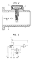
- Fig. 2 shows a hot film type air flow meter of the present invention applied to a suction air flow meter in an internal combustion engine for an automobile.
- reference numeral 1A denotes a thin hot film type exothermic resistance element for use of detecting the air flow rate of an air current
- 1B a thin hot film type temperature sensing resistance element for use of sensing the temperature of the air current
- 3 a control module with an air flow state detecting circuit mounted thereon
- 4 a flow meter main body constituting a part of a suction air passage in the internal combustion engine for the automobile.
- the thin film type or air flow rate detecting exothermic resistance element 1A as a main resistance element and the thin film type temperature sensing resistance element 1B as an auxiliary resistance element have the same construction, an example of which is shown in Figs. 1a, 1b and 1c.
- the thin film type exothermic air flow rate detecting resistance element lA or the thin film type temperature sensing resistance element lB comprises a dielectric substrate member 5A or 5B, a thin film type conductor 6A or 6B as a resistance element forming conductor, a thin film type conductor 6a as an electrode element forming conductor for the thin film type conductor 6A or 6B, two terminals 8a, another thin film type conductor 7A or 7B as a shield electrode element forming conductor, and two terminals 8b.
- the thin film type resistance element forming conductor 6A or 6B of platinum is formed by evaporation on one surface of the flat type dielectric substrate member 5A or 5B, which consists of a rectangular alumina flat plate of about 10.0 mm in length, about 5.0 mm in width and 0 2 - 0.5 mm in thickness, in such a manner that the thin film type resistance element forming conductor 6A or 6B is used as a part of a resistance element.
- Another thin film type shield electrode element forming conductor 7A or 7B is formed by the evaporation of platinum on that portion of the same surface of the dielectric substrate member 5A or 5B which is around the thin film type resistance element forming conductor 6A or 6B and the thin film type shield electrode element forming conductor 7A or 7B.
- the resultant film type conductor 7A or 7B is used as an electrode element.
- the electrode element 7A or 7B works as a shield electrode element forming conductor for shielding the electromagnetic waves or noise.
- the thin film type resistance element forming conductor 6A or 6B and the shield electrode element forming 7A or 7B are then provided with the terminals 8a or the terminals 8b so that they can be connected to outer parts.
- Fig. 3 shows the connected condition in the electric circuit diagram of an air flow state detecting circuit mounted on the control module 3 to the exothermic or air flow rate detecting resistance element lA and the temperature sensing resistance element lB which are constructed as shown in Fig. 2.
- the film type resistance element forming conductor 6 (6A or 6B) in the exothermic or air flow rate detecting resistance element 1A and the temperature sensitive resistance element 1B are connected as shown in Fig. 2.
- the thin film type resistance element forming conductors 6 (6A or 6B) in the exothermic or air flow rate detecting resistance element 1A or the temperature sensitive resistance element 1B is connected to the respective predetermined portion of the air flow rate detecting circuit through the terminals 8a or the terminals 8b with the shield electrode element forming film type conductor 7 (7A or 7B) connected to ground E such as engine block and an automobile body and kept at a common potential which is the lowest potential.
- the exothermic or air flow rate detecting resistance element 1A and the temperature sensing resistance element 1B are assembled unitary with the control module 3 having a shield base member 3a.
- control module 3 is fixed to the flow meter main body 4 which is molded integrally out of PBT (polybutylene terephthalate) resin material or PPS (polypropylene sulfide) resin material, the exothermic or air flow rate detecting resistance element 1A and the temperature sensing resistance element 1B are retained in the respective predetermined positions in the suction air passage of the engine.
- PBT polybutylene terephthalate
- PPS polypropylene sulfide
- an electric current is supplied to the thin film type conductor 6A in the exothermic or air flow rate detecting resistance element 1A, which is controlled so as to be maintained at a constant temperature, for example, around 200°C.
- a constant temperature for example, around 200°C.
- the exothermic or air flow rate detecting resistance element lA and also the temperature sensing resistance element lB be exposed sufficiently to the air current the flow rate of which is to be detected.
- the exothermic or air flow rate detecting resistance element 1A and the temperature sensing resistance element 1B are projected greatly from the control module 3 and retained in this state as shown in Fig. 2.
- the shield electrode element forming thin film type conductor 7A or 7B is provided, which is connected to the ground E and maintained at the lowest potential and a common potential.
- the thin film type shield electrode element forming conductor 7A or 7B is maintained at the lowest potential and the common potential with a sufficiently low impedance in the range of frequency in question, and a radio interference resistance of not less than the value of 100 V/m of the electric field strength shown by curve c in Fig. 4 can be obtained.
- Fig. 5 shows another embodiment of the exothermic or air flow rate resistance element lA or the temperature sensing resistance element lB in the present invention.
- the shield electrode element forming thin film type conductor 7A or 7B is formed on the substantially whole of that surface of a dielectric alumina substrate member 5A or 5B which is on the opposite side of the surface which has a resistance element forming thin film type conductor 6A or 6B.
- the thin film type resistance element forming conductor 6A or 6B of platinum is formed by evaporation on one surface of the flat type dielectric substrate member 5A or 5B, which consists of a rectangular alumina plate.
- the thin film type shield electrode element forming conductor 7A or 7B of platinum is formed by evaporation on another surface of the dielectric alumina substrate member 5A or 5B.
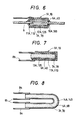
- Fig. 6 shows a further embodiment of the exothermic resistance element 1A or the temperature sensing resistance element 1B in the present invention.
- an alumina tube 12A or 12B of about 0.5 mm in diameter and about 2.0 mm in length is used as a dielectric substrate member, and platinum (Pt) - iridium (Ir) wires 9 are inserted into both end portions of the alumina tube 12A or 12B and held firmly by a glass bonding agent substance 10A or 10B.
- a resistance element forming thin film type conductor 6A or 6B and a shield electrode element forming thin film type conductor 7A or 7B are then formed in the mentioned order on the outer circumferential surface of the resultant alumina tube 12A or 12B with a dielectric film member 11A or 11B of glass sandwiched between the thin film type resistance element forming conductor 6A or 6B and the shield electrode element forming conductor 7A or 7B.
- the thin film type resistance element forming conductor 6A or 6B of platinum is formed by evaporation on the outer surface of the alumina tube 12A or 12B.
- the thin film type shield electrode element forming conductor 7A or 7B of platinum is formed by evaporation on the outer surface of the dielectric film member 11A or 11B.
- a lead wire is connected to the shield electrode element forming thin film type conductor 7A or 7B so that the shield electrode forming thin film type conductor 7A or 7B can be connected to ground E.
- electro-static capacities are formed between their respective inner and outer thin film type resistance element forming conductor 6A or 6B and shield electrode element forming conductor 7A or 7B with the outer thin film type shield electrode element forming conductor 7A or 7B connected to ground E, whereby a sufficiently high radio interference resistances can be obtained.
- Fig. 7 shows a still embodiment of the exothermic resistance element 1A or the temperature sensing resistance element 1B in the present invention using a rod type dielectric substance member.
- a rod type alumina dielectric substance member 13A or 13B is used, and a resistance element forming thin film type conductor 6A or 6B and a shield electrode element forming thin film type conductor 7A or 7B are laminated on the outer circumferential surface of the alumina dielectric substrate member 13A, 13B with a dielectric film member 11A or 11B of glass sandwiched between the thin film type resistance element forming conductor 6A or 6B and the shield electrode element forming conductor 7A or 7B.
- the thin film type resistance element forming conductor 6A or 6B of platinum is formed by evaporation on the outer surface of the alumina dielectric substrate member 13A or 13B.
- the thin film type shield electrode element forming conductor 7A or 7B of platinum is formed by evaporation on the outer surface of the dielectric film member 11A or 11B.
- electro-static capacities are formed between their respective inner and outer thin film type resistance element forming conductor 6A or 6B and shield electrode element forming conductor 7A or 7B with the outer thin film type shield electrode element forming conductor 7 connected to ground E, whereby a sufficiently high radio interference resistances can be obtained.
- Fig. 8 shows an another further embodiment of the exothermic or air flow rate detecting resistance element 1A or the temperature sensing resistance element 1B in the present invention using a bottomed tube type dielectric substrate member.
- a bottomed tube type alumina dielectric substrate member 14A or 14B is used, and a resistance element forming thin film type conductor 6A or 6B is laminated on the outer circumferential surface of the alumina dielectric tube 14A or 14B and a shield electrode element forming thin film type conductor 7A or 7B is laminated on the inner circumferential surface of the alumina dielectric tube 14A or 14B.
- the thin film type resistance element forming conductor 6A or 6B of platinum is formed by evaporation on the outer surface of the alumina dielectric tube 14A or 14B.
- the thin film type shield electrode element forming conductor 7A or 7B of platinum is formed by evaporation on the inner surface of the alumina dielectric tube 14A or 14B.
- electro-static capacities are formed between their respective inner and outer thin film type shield electrode element forming conductor 7A or 7B and resistance element forming conductor 6A or 6B with the inner thin film type shield electrode element forming conductor 7A or 7B connected to ground E, whereby a sufficiently high radio interference resistances can be obtained.
Landscapes
- Physics & Mathematics (AREA)
- Fluid Mechanics (AREA)
- General Physics & Mathematics (AREA)
- Measuring Volume Flow (AREA)
Applications Claiming Priority (2)
| Application Number | Priority Date | Filing Date | Title |
|---|---|---|---|
| JP62142297A JPS63307315A (ja) | 1987-06-09 | 1987-06-09 | ホツトフイルム形空気流量計 |
| JP142297/87 | 1987-06-09 |
Publications (2)
| Publication Number | Publication Date |
|---|---|
| EP0294689A1 EP0294689A1 (en) | 1988-12-14 |
| EP0294689B1 true EP0294689B1 (en) | 1992-04-01 |
Family
ID=15312101
Family Applications (1)
| Application Number | Title | Priority Date | Filing Date |
|---|---|---|---|
| EP88108679A Expired - Lifetime EP0294689B1 (en) | 1987-06-09 | 1988-05-31 | Hot film type air flow meter |
Country Status (5)
| Country | Link |
|---|---|
| US (1) | US4829814A (enExample) |
| EP (1) | EP0294689B1 (enExample) |
| JP (1) | JPS63307315A (enExample) |
| KR (1) | KR920006963B1 (enExample) |
| DE (1) | DE3869664D1 (enExample) |
Families Citing this family (18)
| Publication number | Priority date | Publication date | Assignee | Title |
|---|---|---|---|---|
| JPH0820292B2 (ja) * | 1989-04-14 | 1996-03-04 | 株式会社日立製作所 | 内燃機関用吸入空気流量計測装置 |
| JPH06105177B2 (ja) * | 1989-08-29 | 1994-12-21 | 三菱電機株式会社 | 感熱式流量センサ |
| DE9006967U1 (de) * | 1990-06-22 | 1991-10-24 | Sensycon Gesellschaft für industrielle Sensorsysteme und Prozessleittechnik mbH, 30179 Hannover | Widerstandselement |
| JP2690066B2 (ja) * | 1990-12-25 | 1997-12-10 | 三菱電機株式会社 | 感熱式流量センサ |
| US5201221A (en) * | 1991-03-15 | 1993-04-13 | Ford Motor Company | Flow sensor and method of manufacture |
| JP3240733B2 (ja) * | 1993-03-17 | 2001-12-25 | 株式会社日立製作所 | 熱式空気流量計 |
| US5583295A (en) * | 1994-03-14 | 1996-12-10 | Nippondenso Co., Ltd. | Pressure sensor having gauge resistors and temperature compensating resistors on the same surface |
| US5525040A (en) * | 1994-03-31 | 1996-06-11 | B&B Financial Planning Inc. | Controller for oil wells with a thermal dispersion probe |
| DE19509555B4 (de) * | 1995-03-16 | 2006-01-19 | Robert Bosch Gmbh | Durchflußsensor |
| US5984641A (en) * | 1997-05-05 | 1999-11-16 | 1273941 Ontario Inc. | Controller for oil wells using a heated probe sensor |
| JP3867393B2 (ja) * | 1998-03-20 | 2007-01-10 | 株式会社デンソー | マイクロヒータおよびその製造方法ならびにエアフローセンサ |
| JP3468727B2 (ja) * | 1999-09-24 | 2003-11-17 | 株式会社日立製作所 | 熱式空気流量計 |
| US6477901B1 (en) * | 1999-12-21 | 2002-11-12 | Integrated Sensing Systems, Inc. | Micromachined fluidic apparatus |
| CN101405581B (zh) * | 2006-03-28 | 2011-07-20 | 株式会社岛津制作所 | 热质流量计 |
| FR2901878B1 (fr) * | 2006-06-02 | 2012-08-17 | Sc2N Sa | Capteur pour la detection du niveau d'un liquide |
| WO2015155630A1 (en) | 2014-04-11 | 2015-10-15 | Koninklijke Philips N.V. | Needle with thin film piezoelectric sensors |
| DE102014217870A1 (de) * | 2014-09-08 | 2016-03-10 | Robert Bosch Gmbh | Sensoranordnung zur Bestimmung wenigstens eines Parameters eines durch einen Messkanal strömenden fluiden Mediums |
| DE102018221847A1 (de) * | 2018-12-14 | 2020-06-18 | Robert Bosch Gmbh | Elektrische Vorrichtung mit einem Sensor |
Family Cites Families (8)
| Publication number | Priority date | Publication date | Assignee | Title |
|---|---|---|---|---|
| DE2925975A1 (de) * | 1979-06-27 | 1981-01-15 | Siemens Ag | Mengendurchflussmesser |
| JPS5676012A (en) * | 1979-11-27 | 1981-06-23 | Hitachi Ltd | Measuring device of suction air quantity |
| JPS57173758A (en) * | 1981-04-20 | 1982-10-26 | Hitachi Ltd | Hot wire type current meter |
| DE3248462A1 (de) * | 1982-12-29 | 1984-07-12 | Robert Bosch Gmbh, 7000 Stuttgart | Luftmassenmessvorrichtung |
| JPS59162413A (ja) * | 1983-03-07 | 1984-09-13 | Hitachi Ltd | 熱式流量計 |
| JPS61274222A (ja) * | 1985-05-30 | 1986-12-04 | Sharp Corp | 流量センサ |
| WO1987000917A1 (en) * | 1985-08-09 | 1987-02-12 | Motorola, Inc. | Mass airflow sensor |
| US4635475A (en) * | 1985-10-31 | 1987-01-13 | General Motors Corporation | Hot element mass airflow sensor |
-
1987
- 1987-06-09 JP JP62142297A patent/JPS63307315A/ja active Granted
-
1988
- 1988-05-31 DE DE8888108679T patent/DE3869664D1/de not_active Expired - Lifetime
- 1988-05-31 EP EP88108679A patent/EP0294689B1/en not_active Expired - Lifetime
- 1988-06-07 US US07/203,447 patent/US4829814A/en not_active Expired - Lifetime
- 1988-06-09 KR KR1019880006875A patent/KR920006963B1/ko not_active Expired
Also Published As
| Publication number | Publication date |
|---|---|
| KR920006963B1 (ko) | 1992-08-22 |
| KR890000882A (ko) | 1989-03-17 |
| DE3869664D1 (de) | 1992-05-07 |
| JPH0476614B2 (enExample) | 1992-12-04 |
| US4829814A (en) | 1989-05-16 |
| JPS63307315A (ja) | 1988-12-15 |
| EP0294689A1 (en) | 1988-12-14 |
Similar Documents
| Publication | Publication Date | Title |
|---|---|---|
| EP0294689B1 (en) | Hot film type air flow meter | |
| EP0323694B1 (en) | Thermal air flow meter | |
| US4320364A (en) | Capacitor arrangement | |
| US20030071640A1 (en) | Capacitive sensor assembly for use in a non-contact obstacle detection system | |
| JP2001506723A (ja) | 容量センサ組立体 | |
| JP2734997B2 (ja) | 圧電センサ | |
| US4935710A (en) | High frequency filter for electric instruments | |
| US4782310A (en) | High frequency filter assembly for electric instrument | |
| US5443550A (en) | Electronic circuit apparatus, apparatus for removing electromagnetic wave noise and the method of manufacturing the same | |
| US4378504A (en) | Proximity switch | |
| US7019539B2 (en) | Thickness detecting sensor | |
| EP0145457A2 (en) | An infrared sensor | |
| JP3684687B2 (ja) | 静電容量型近接センサ | |
| US4354219A (en) | Capacitance sensing device | |
| CN217292408U (zh) | 电子皮肤、机械臂和机器人 | |
| US6462642B1 (en) | High-voltage variable resistor | |
| JP3002276B2 (ja) | 湿度センサ | |
| JPH06109508A (ja) | 感温抵抗体の支持構造、その回路のハウジング及びこれらを用いた空気流量計 | |
| US5438269A (en) | Sparking voltage detecting device having an embedded conductive member | |
| JPS593467Y2 (ja) | 近接スイッチ | |
| JPH0192620A (ja) | 静電容量型レベルセンサー | |
| JPH04353753A (ja) | 湿度センサー | |
| JPH08101054A (ja) | 流量計 | |
| JPH0548106Y2 (enExample) | ||
| JPH0529109A (ja) | バリスタ部品 |
Legal Events
| Date | Code | Title | Description |
|---|---|---|---|
| PUAI | Public reference made under article 153(3) epc to a published international application that has entered the european phase |
Free format text: ORIGINAL CODE: 0009012 |
|
| AK | Designated contracting states |
Kind code of ref document: A1 Designated state(s): DE GB |
|
| 17P | Request for examination filed |
Effective date: 19881219 |
|
| 17Q | First examination report despatched |
Effective date: 19900625 |
|
| GRAA | (expected) grant |
Free format text: ORIGINAL CODE: 0009210 |
|
| AK | Designated contracting states |
Kind code of ref document: B1 Designated state(s): DE GB |
|
| REF | Corresponds to: |
Ref document number: 3869664 Country of ref document: DE Date of ref document: 19920507 |
|
| PLBE | No opposition filed within time limit |
Free format text: ORIGINAL CODE: 0009261 |
|
| STAA | Information on the status of an ep patent application or granted ep patent |
Free format text: STATUS: NO OPPOSITION FILED WITHIN TIME LIMIT |
|
| 26N | No opposition filed | ||
| REG | Reference to a national code |
Ref country code: GB Ref legal event code: IF02 |
|
| PGFP | Annual fee paid to national office [announced via postgrant information from national office to epo] |
Ref country code: DE Payment date: 20070606 Year of fee payment: 20 |
|
| PGFP | Annual fee paid to national office [announced via postgrant information from national office to epo] |
Ref country code: GB Payment date: 20070426 Year of fee payment: 20 |
|
| REG | Reference to a national code |
Ref country code: GB Ref legal event code: PE20 Expiry date: 20080530 |
|
| PG25 | Lapsed in a contracting state [announced via postgrant information from national office to epo] |
Ref country code: GB Free format text: LAPSE BECAUSE OF EXPIRATION OF PROTECTION Effective date: 20080530 |