EP0293533A2 - Verfahren und Vorrichtung mit Verschiebungsausblendung und Kompandierung für digitale Kodierung und Dekodierung von Hi-Fi-Audiosignalen - Google Patents
Verfahren und Vorrichtung mit Verschiebungsausblendung und Kompandierung für digitale Kodierung und Dekodierung von Hi-Fi-Audiosignalen Download PDFInfo
- Publication number
- EP0293533A2 EP0293533A2 EP87309331A EP87309331A EP0293533A2 EP 0293533 A2 EP0293533 A2 EP 0293533A2 EP 87309331 A EP87309331 A EP 87309331A EP 87309331 A EP87309331 A EP 87309331A EP 0293533 A2 EP0293533 A2 EP 0293533A2
- Authority
- EP
- European Patent Office
- Prior art keywords
- pcm data
- values
- data values
- pcm
- block
- Prior art date
- Legal status (The legal status is an assumption and is not a legal conclusion. Google has not performed a legal analysis and makes no representation as to the accuracy of the status listed.)
- Withdrawn
Links
Images


Classifications
-
- H—ELECTRICITY
- H03—ELECTRONIC CIRCUITRY
- H03M—CODING; DECODING; CODE CONVERSION IN GENERAL
- H03M7/00—Conversion of a code where information is represented by a given sequence or number of digits to a code where the same, similar or subset of information is represented by a different sequence or number of digits
- H03M7/14—Conversion to or from non-weighted codes
- H03M7/24—Conversion to or from floating-point codes
-
- H—ELECTRICITY
- H03—ELECTRONIC CIRCUITRY
- H03M—CODING; DECODING; CODE CONVERSION IN GENERAL
- H03M7/00—Conversion of a code where information is represented by a given sequence or number of digits to a code where the same, similar or subset of information is represented by a different sequence or number of digits
- H03M7/30—Compression; Expansion; Suppression of unnecessary data, e.g. redundancy reduction
- H03M7/50—Conversion to or from non-linear codes, e.g. companding
Definitions
- This invention generally relates to digital techniques for the representation, transmission and reproduction of audio signals. More particularly, this invention relates to digital audio signal processing systems which use companding techniques in connection with encoding, recording, transmitting or decoding broadcast-quality audio signals.
- Multichannel digital circuits for the transmission of audio signals is becoming increasingly common because of a variety of associated advantages, including simplicity, convenience and economy.
- Digitally encoded audio signals are easily multiplexed and de-multiplexed, and error detecting or correcting codes are readily employed for noise immunity.
- Multichannel PCM (pulse code modulation) systems for example, have been developed for carrying stereo program material between studio centers and main transmitters. Such a system, transmitting 13 audio channels over a line designed for carrying a standard television signal, is described in F. Mazada (editor), Electronics Engineer's Reference Book , 5th ed., Butterworths, Boston, Mass., (1983), pp. 54/21-54/22.
- CDs Compact digital discs
- a typical problem with audio transmission is that the signal-to-noise ratio varies with the amplitude of the audio signal.
- the noise may become obtrusive during gaps between syllables. It is conventional to overcome this problem by the process of companding, which involves the compression of the amplitude variations in the audio signal before transmission, and expansion of the received signal after detection at the receiver. Companding permits efficient transmission of audio signals by effectively varying the noise level depending on the signal level, the noise being least at the lowest signal levels and highest at maximum signal levels.
- Companding is readily performed with digital circuits, and is useful for bandwidth compression as well as for concealing background noise.
- a typical digital system employing companding is the NICAM-3 developed by the BBC ("NICAM-3," The Radio and Electronic Engineer , 50, No. 10, pp. 519-530, Oct 1980).
- the NICAM-3 system uses nearly instantaneous companding in which the system periodically samples an audio signal and initially codes the samples to 14-bit accuracy by performing analog-to-digital conversion.
- the NICAM system further encodes the digitized samples by using a set of four linear coding scales having maximum amplitudes in six-dB steps.
- the samples are processed in blocks of sixteen consecutive samples, and the amplitude of the largest sample in each block is used to determine which of the available coding scales is used for the block.
- the chosen scale is the lowest of the four scales which can completely accommodate the largest sample. Since each of the linear scales has a 10-bit resolution, the encoded samples undergo a digital compression from 14 bits per sample to 10 bits per sample. Decoding of the transmitted data is accomplished by including a data channel multiplexed with the original data stream in order to indicate to the receiver which scale is to be selected to decode each block of received samples.
- the NICAM-3 system uses what is generally known as "floating-point PCM".
- floating-point PCM As described in A. Oppenheim (editor), Applications of Digital Signal Processing , Prentice-Hall, Englewood Cliffs, N.J. (1978), pp. 38-41, the control of the coding scale factor for floating-point PCM can also be "instantaneous" or "syllabic". When it is instantaneous, the scale factor is determined for each sample. When it is syllabic, the scale factor is decreased whenever the converter would have been overloaded, but it is not increased until after the signal has remained below half-scale for a predetermined waiting period. Typical waiting periods are on the order of 100 to 300 milliseconds.
- a near-instantaneous companding method similar to floating-point PCM is disclosed in Shutterly U.S. Patent 4,295,223.
- a common scale factor is selected for each TV field.
- the common scale factor is either 1, 2, 4, 9, 16 or 32, and the largest one of these is selected which does not cause the companded audio signal to exceed the peak signal limits.
- a three-bit code is transmitted in the vertical retrace interval of each field in order to indicate the selected scale factor.
- the audio signal is converted to PCM samples, the scale factor is selected based on the values of the samples, and the samples are multiplied by the scale factor.
- the companded samples are fed to a digital-to-analog converter for generating an analog sample for each companded sample.
- Each analog sample is inserted as a pulse into a corresponding line of the video signal.
- the scrambler transmits the video signal to at least one descrambler where an analog-to-digital converter converts the analog samples to corresponding digital values.
- the digital values are divided by the scale factor indicated by the three-bit code.
- the digital values obtained at the descrambler might not be equal to their corresponding values at the scrambler due to bias shift between the scrambler and descrambler converters.
- a preselected mid-range level from the digital-to-analog converter is transmitted as an analog pulse in each field of the video signal.
- the mid-range level is said to be set to the mean of the upper and lower limits of the analog samples.
- the mid-range pulse is received by the descrambler and converted to a corresponding value for removing the effect of any bias shift from the digital values prior to division by the scale factor.
- Floating-point PCM allows an increased number of audio channels to be transmitted for a system of given bit capacity by virtue of the reduced bit rate resulting from the digital compression.
- Such systems are susceptible to problems stemming from the fact that audio energy in typical audio broadcasts tends to be concentrated at the lower frequencies. The non-uniform energy distribution across the frequency spectrum may cause undue distortion of the upper frequency signals at the receiver end.
- a primary object of the invention is to provide an improved method for digitally encoding and decoding stereo broadcast quality audio signals.
- a related object of the invention is to provide such an improved digital encoding and decoding method which does not produce distortion of upper frequency signals as a result of non-uniform energy distribution across the frequency spectrum.
- a further object of the invention is to provide a digital recording or transmission system for stereo broadcast quality audio signals which has a wide dynamic range, uniform amplitude response, and enhanced noise immunity.
- a further object of the invention is to provide an improved audio transmission system which is particularly applicable to the transmission of several digitally sampled stereo audio signals over a conventional cable television channel.
- a related object of the invention is to provide such an improved audio transmission system which uses a decoder that is economical to mass produce.
- an audio signal represented by a series of high-resolution pulse code modulated (PCM) data at a predetermined rate is compressed by extracting a lower rate series of representative values.
- the PCM data are adjusted by offsetting in accordance with corresponding representative values, and the adjusted PCM data are then companded.
- the combination of the series of representative values and the companded PCM data provides a rate-compressed representation of the audio signal which is capable of being decoded after transmission or storage to reproduce the audio signal without substantial noise, distortion or loss of dynamic range.
- a digital audio transmission system accepts a stereo audio signal in the form of 16-bit pulse code modulated (PCM) data.
- PCM pulse code modulated
- An encoder converts the PCM data to a pseudo-floating-point format which is then transmitted over a transmission link to the end user.
- a decoder reconstructs the received data into a 16-bit PCM format in order to yield the originally encoded stereo audio signal.
- the pseudo-floating-point conversion performed by the encoder preferably compresses the PCM data fed to it by processing the data in blocks, each of which consists of a plurality of samples.
- the sample values obtained for each block are centered about a zero reference level by extracting and subtracting a common offset value so that data within a block extend over an equally distributed range. Since the centering process is performed before conversion of the PCM data to the pseudo-floating-point format, any large common offset for the block, such as is typically caused by a high amplitude low frequency audio signal, is substantially eliminated prior to conversion. This centering process limits the normally destructive effect that low frequency signals of a high amplitude have upon high frequency signals of relatively low amplitude. The audio frequency below which cancellation occurs is preselected by preselecting the number of samples within a sample block. Moreover, since the offset for each block is transmitted to the decoder, the low frequency component of the audio signal is always represented by a relatively high degree of precision.
- a binary exponent of the pseudo floating-point representation for a given block is chosen in accordance with the largest absolute magnitude found among all samples within a block after the centering process.
- the exponent is selected so that the largest sample is representable in floating-point representation with the maximum amount of precision.
- a few bits of error correction data are included in the pseudo-floating-point format to protect the integrity of the binary exponent and the common offset value for each block and thereby insure proper decoding, even if there is substantial noise in the transmission channel.
- a parity bit is provided for each floating-point value for noise protection in the usual manner.
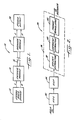
- FIG. 1 there is shown in simplified block diagram form a stereo audio signal transmission system embodying the present invention.
- the audio encoding and transmission system 10 is shown subdivided into its most basic components.
- An audio signal source 12 supplies audio signals to an encoder module 14 for encoding prior to transmission.
- the audio source 12 supplies dual audio channels (left and right) of a stereo broadcast video channel to the encoder module 14.
- the encoder module 14 samples the stereo audio signals, converts the samples to digital form, and further encodes the samples in a compression process which, for instance, allows an increased number of audio channels to be fit within a single video broadcast channel.
- the signal in each audio channel is converted into 16-bit pulse code modulated (PCM) data.
- PCM pulse code modulated
- the PCM data are converted into a pseudo-floating-point format, through a compression process which processes the PCM data in the form of a series of blocks each consisting of a predetermined number of consecutive samples.
- the data for each block are adjusted by a common offset value which is calculated as the mean value of the maximum and minimum sample values in the block, so that the adjusted data are evenly distributed or centered within a certain range for floating-point representation.
- Encoded data from the encoder module 14 are transmitted over a conventional broadcast link 16 such as a cable link for linking together a plurality of subscribers to a cable television channel.
- the transmitted encoded data are received by a decoder module 18 which converts the pseudo-floating-point representation of the encoded data back to the PCM format.
- the PCM data for the left and right stereo channels are fed to separate digital-to-analog converters.
- the stereo audio signals from the decoder provide stereo output 20 which, for example, is reproduced by a conventional stereo high-fidelity amplifier with speakers.
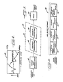
- FIG. 2 there is shown a more detailed block diagram of a single audio channel 30 of the encoder module (14 in FIG. 1) for use with the system of FIG. 1.
- the encoder module 14 of FIG. 1 includes two of the channels as shown in FIG. 2 for encoding the stereo signals.
- Audio signals are received through an analog-to-digital converter (ADC) 32 which samples the analog signals and converts them into corresponding digital values.
- ADC 32 is fed directly from the audio channel corresponding to a particular video channel to be transmitted.
- the ADC samples the audio-signals at a periodic rate of 56.8 kHz and provides 16-bit PCM values.
- the sampled 16-bit PCM data from the ADC 32 are fed to a digital signal processor DSP 34 which essentially performs a low-pass filtering operation upon the digitized audio signals along with a decimation/interpolation operation which brings about a desired sampling frequency change.
- the DSP changes the original sampling frequency to a lower frequency which preferably is most compatible with the video chrominance frequency components associated with the video channel with which the processed audio is to be broadcast. Specifically, the DSP brings about a change in the ADC sampling frequency from 56.8 kHz to 37.879 kHz.
- the low-pass filtering operation performed by the DSP 34 is selected to have good stop-band rejection qualities to reject frequencies above 18.939 kHz since a change of sampling frequency requires the removal of all "image" energy from the input audio signal to prevent non-linear "aliasing" distortion. This allows the encoding and transmission of the full audio bandwidth associated with cable television channels (which generally is 18 kHz).
- the low-pass filtering performed by the DSP ensures that no image signal energy is included within the pass band of the filtering operation and hence the associated non-linear distortion is avoided.
- the ADC 32 followed by the DSP 34 is a preferred alternative to an anti-aliasing analog low-pass filter followed by an analog-to-digital converter sampling at the 37.879 kHz rate, since the digital low-pass filtering provided by the DSP can be superior to that of an analog low-pass filter.
- the ADC-DSP technique for analog-to-digital conversion is further described in A. Oppenheimer, Applications of Digital Signal Processing , Prentice-Hall, Englewood Cliffs, N.J. (1978) pp. 6-7.
- Compact audio discs could also be used as a source of 16-bit PCM audio data.
- Standard CDs provide 16-bit PCM data at a rate of about 44.1 kHz.
- a number of CD player units could be used with their time base oscillators wired together to provide synchronized PCM data.
- the 16-bit PCM data from the audio source is provided to an encoder 30.
- the encoder converts the PCM data fed to it into a pseudo-floating-point representation before transmitting the data by using one of the many conventional data transmission techniques, such as raised cosine pulse shaping.
- the transmission and reception of multi-channel PCM data over a television channel using such a conventional transmission technique is further described in F. Mazda (editor), Electronics Engineer's Reference Book , 5th ed., Butterworths, Boston MA (1983), pp. 54/21 to 54/22. Actual transmission is performed via amplitude modulation (AM) over the transmission link to the subscriber.
- AM amplitude modulation
- compression of the PCM data is obtained by processing it in the form of blocks, each containing a plurality of samples.
- a common offset value "K" and a common floating-point exponent is determined for each block.
- the preferred embodiment uses blocks consisting of 16 audio samples.
- the sampled values for each of the sample blocks are centered by extracting the common offset value K. More specifically, the offset value K is calculated as the median value between the maximum value and the minimum value found within the sample block. Subsequently, the offset value K is subtracted from each of the 16 samples in the block in order to effectively center the samples about a zero reference level. At this stage, the block data extend over an equally distributed range from the maximum value to the minimum value.
- the extraction of the common offset is performed within the encoder module 36 by an offset extractor 38 and increases the effective resolution of the encoding procedure by preventing large low frequency signals from overriding any low amplitude high frequency signals.
- the offset extraction forms an important feature of this invention and directly contributes to the non-destructive characteristics of the illustrative encoding procedure, as described below.
- the number of samples within a block to be encoded determines the extent of cancellation of distorting low frequency components produced by the encoding procedure.
- the centering procedure functions as a single pole high-pass filter with a cut-off frequency equal to the Nyquist frequency divided by the number of samples per block.
- the Nyquist frequency is 18.939 kHz. Therefore, for 16 samples per block, the cut-off frequency is 1.184 kHz.
- the centering procedure cancels a 1.184 kHz signal component by a factor of 3 dB.
- the cancellation factor increases for lower frequency components and almost total cancellation (by more than 20 dB) occurs for low frequency components having frequencies of 100 Hz or less.
- the low frequency components are removed prior to companding, they are encoded separately in the offsets and are replaced during the decoding process.
- the extraction of the common offsets hence provides the encoding procedure with a relative independence between audio signals of extremely low and extremely high frequency without any loss of precision that would be associated with a filtering operation.
- the common binary component is a 3-bit value.
- the encoder module performs the actual format translation from the 16-bit PCM to a corresponding pseudo-floating-point representation through a format translator 42 by effectively left-shifting all of the centered 16-bit PCM values by a number of places specified by the exponent and truncating to eight bits per value. Finally, the encoded data is transmitted over the transmission link (16 in FIG. 1).
- the encoded data can be transmitted in any convenient form. Although the offsets and the exponents are preferably transmitted in digital form to ensure virtually error free transmission, the floating-point values do not require as much error protection as the offsets and exponents.
- the floating-point values could be transmitted as analog pulses (as in Shutterly U.S. patent 4,295,223) or as an analog waveform or waveform segments. If analog waveform segments are transmitted, the beginning and ending portions should be extended (so that the first portion of a following segment must repeat the last portion of a preceding segment) since the extreme beginning and ending portions become slightly distorted due to band-limiting effects and therefore should not be used for conveying values.
- FIG. 3 there is shown a block diagram of one audio channel 50 of the decoder module (18 in FIG 1).
- a tuner and demodulator 52 accepts the transmitted encoded data and demodulates it before presenting it to a decoder 54.
- the decoder includes a format translator 56 which functions to reconvert the audio signals from their pseudo-floating-point representation (as produced at the encoding stage) back to fixed-point representation.
- the fixed-point data is next processed by an offset injector 58 which combines the fixed-point data with the corresponding block offsets in order to obtain the complete audio data representation for a given sample block.
- the decoded output signals of the decoder module 54 are then passed on to a digital-to-analog converter 60 which translates the digital values into corresponding analog signals which are used to generate an audible output by interfacing with the subscriber equipment (e.g. a stereo hi-fi amplifier and speakers) at the decoder end.
- subscriber equipment e.g. a stereo hi-fi amplifier and speakers
- the samples can possibly range from a negative value of 8000 (HEX) to a positive value of 7FFF (HEX).
- the PCM data at the input of the encoder is processed in sample blocks consisting of 16 samples each and, as shown, the common value K is determined as the median value between the maximum value P and the minimum value Q within the block.
- the median or common offset value K is then subtracted from the value of each sample within the block so that each of the 16 samples within the block is at this stage centered about the value K, so that the audio data extend over an equally distributed range from the maximum value P to the minimum value Q. Since the block centering procedure occurs before conversion to the floating-point format, the above scheme prevents the floating-point representation from including any large common offsets as is typically caused by large amplitude, low frequency signals.
- the normalized sample having the largest absolute magnitude within the 16 samples in a block is used as the basis for determining the common 3-bit binary exponent for the pseudo-floating-point representation of the block.
- the encoding system of this invention employs eight ranges to compress from 16 to 8 bits, and the selection of a particular range is made by examining the 8 most significant bits of each sample and determining a 3-bit binary exponent which best indicates the highest range required by each group of 16 samples. In numerical terms, the exponent is indicated by the number of binary places, up to a maximum of 7, that the 16-bit normalized data can be left-shifted without overflow.
- Data compression is obtained as part of the conversion to the floating point representation for a sample block by means of a shift operation upon the 16-bit value representing the magnitude of each sample.
- the binary exponent for each group of 16 samples provides an indication of which 8 bits of each 16-bit sample value are to be discarded by controlling the shift operation in such a way that the desired number of bits are deleted from appropriate positions within each 16-bit sample value.
- the precision of the floating-point representation is relatively independent of the low-frequency signal amplitude and increases with decreased high-frequency signal amplitude.
- Samples having centered values that are higher in level than half the maximum permissible peak amplitude are coded to a precision of 8 bits.
- coding accuracy is retained at the maximum possible resolution of 16 bits per sample.
- an inverse operation is performed.
- the decoder module is loaded sequentially with the 8-bit value representing the magnitude of each compressed sample.
- the 3-bit binary exponent is then used to perform in effect an arithmetic right-shift operation by the number of binary places indicated by the exponent to reproduce substantially the original 16-bit magnitude of a sample.
- the fixed-point to floating-point conversion procedure is better understood by considering a numerical example. For instance, consider the case where the largest value of all the centered samples within the 16-sample block is 3CFA (HEX). This value is normalized by a shift operation in the left direction by one position resulting in a value of 79F4 (HEX) which represents the largest positive value that can be contained in a predetermined positive limit of 7FFF (HEX). The truncation process thereby yields an 8-bit number represented by the value 79 (HEX). The binary exponent value is set to -1, since one left shift was used. The truncated representation, when converted back to 16-bit PCM format at the decoder, has a value of 3D00 (HEX).
- HEX 3CFA
- a given block of 16 data points can be expressed by a common 8-bit offset value K, a common 3-bit binary integer exponent having a value of zero to 7 for representing the magnitude of the exponent, and an 8-bit data value for each of the samples within the block.
- FIG. 5 is a representation of the data frame format for a sample block consisting of 16 audio samples.
- the data format includes a 5-bit error correction code for the offset K and the binary exponent, the 3-bit binary exponent for the block, the 8-bit offset value K, and the 9-bit data values for each of the 16 samples within the block.
- Each of the 9-bit data values comprises 8 bits of data for the sample along with an added bit for parity checks.
- the decoder uses the parity check to isolate erroneous data values and replace each erroneous value by either the previous value or an interpolated value.
- the representation shown in FIG. 5 requires a total of just 160 bits in order to represent every block of 16 audio samples.
- the chrominance frequency associated with conventional cable television system is 3.579545 mHz and this is used by the encoding system to generate a transmission baud rate having a value of twice the chrominance carrier frequency or 7.159090 megabaud.
- the chosen baud rate when divided by the selected changed sampling frequency yields the corresponding bit rate for the transmission system.
- the choice of the sampling frequency of 37.879 kHz along with the 7.16 megabaud rate yields a data bit rate of 189 for a single sampling interval, and correspondingly allows the transmission of 3024 bits in the 16 sampling intervals of the selected 16 sample block.
- the representation of FIG. 5 permits the transmission of nine stereo audio channels over a single video channel along with the provision of a partial channel for additional information, such as a frame synchronization code and housekeeping data.
- the audio data is compressed from the original 16 bits for each of the 16 samples within a block, i.e., an original total of 256 bits, to a compressed total of 139 bits including the 3-bit binary exponent, the 8-bit offset K value and 8 bits for each of the 16 samples for the sample block.
- the overall compression ratio obtained is hence 1.8417.
- the encoder for encoding audio data in the compressed format of FIG. 5.
- the encoder generally designated 80, includes a 16-bit numerical processor 81 for performing the computations and comparisons required for the encoding process.
- the processor 81 operates on a periodic or interrupt basis to process in real time each audio sample provided by an analog-to-digital converter ADC 82 and a digital signal processor DSP 83 operating in the fashion previously described.
- the encoded data rate is different from the sampling rate provided by the ADC 82 and the DSP 83. These rates, however, must be precisely related to each other according to the ratio of the number of audio samples processed per frame (for example 16) to the number of encoded data bits per frame (for example, 160 as shown in FIG. 5).
- the encoder 80 includes a sync generator 84 including a PCM bit counter 85 counting at the PCM bit rate and the audio sampling rate, and a frame counter 86 counting the transmitted bits as they are transmitted.
- the sync generator 84 includes means for synchronizing the PCM bit counter 85 and the frame counter 86 so that they are in effect phase-locked at the frame rate.
- the synchronizer 84 is shown for a simplified system in which the encoded data includes data for only a single audio channel and in which a 32-bit frame synchronization code is appended to the data frame format of FIG. 5. Due to this simplification, the ratio of the PCM bit rate to the encoded data rate (including the 32-bit frame synchronization code) is 256/192 or a ratio of 4/3. Therefore, the frame counter 86 is synchronized to the PCM bit counter 85 by clocking them from a common transmitter data clock 87 oscillating at four times the encoded bit rate, and by clocking the PCM bit counter 85 by a divide-by-three counter 88, and clocking the frame counter 86 by a divide-by-four counter 89.
- the PCM bit counter is reset when the frame counter "rolls over".
- a delay flip-flop 90 and a NOR gate 91 are wired as a transition detector to sense the high-to-low transition of the most significant output Q N of the frame counter 86.
- the NOR gate 91 generates a reset pulse which resets the PCM bit counter 85.
- a shift register 92 which is clocked in synchronism with the frame counter 86 and which receives the reset pulse from the gate 91 to perform a parallel load of a frame of data.
- These data include the frame sync code, which is wired into the parallel inputs 93 of the shift register, and also data from a number of latches which comprise in combination a frame buffer 94. Therefore it is necessary for the 16-bit processor 81 of the encoder to periodically store encoded data in the frame buffer 94 prior to the parallel loading of the shift register 92.
- the encoder 80 in FIG. 6 is shown for encoding and transmitting a single channel of audio data
- a number of audio channels are transmitted merely by increasing the length of the shift register 92 and increasing the clocking rate of the frame counter 86 to accommodate the higher encoded data rate required for transmitting encoded data for a number of audio channels from the shift register.
- the frame synchronization code is preferably interleaved with the encoded data for the various audio channels.
- nine stereo audio channels, along with a frame synchronization code and other housekeeping data can be transmitted over a single video channel as described above.
- the components other than the sync generator 84 and the shift register 92 are merely duplicated for each audio channel in such a multi audio channel system.
- the frame buffer 94 corresponds to the data frame format of FIG 5. Specifically, there is provided a 16-bit latch for receiving the 5 bits of error correction code, the 3 bits of the block exponent, and the 8 bits of the block offset K. There is also provided sixteen 9-bit latches generally designated 96 for receiving the 144 bits of the block data.
- interface logic circuits For interfacing the numerical processor 81 to the frame buffer 94, the sync generator 84 and the ADC 82 and DSP 83, there are provided interface logic circuits generally designated 97.
- the DSP 83 is connected to a bidirectional data bus 98 via a 16-bit latch 99.
- the latch 98 is clocked at the PCM word rate indicated by the output Q4 of the PCM bit counter 85.
- the numerical processor 81 is interrupted at this rate via an interrupt line 100 to periodically process the 16 bit PCM value received in the latch 99.
- the outputs Q8-Q5, defining a pointer value POINT ranging from 0 to 15, are fed to the data bus 98 through a tri-state buffer 101.
- the buffer is configured so that the outputs Q8-Q5 are fed to the data inputs D3-D0 of the numerical processor 81, and so that zeros are fed to the more significant bit inputs D15-D4. Therefore, the numerical processor 81 may read a pointer value POINT as a 16-bit number ranging in value from 0 to 15.
- the pointer value is used as an index to reference circular buffers, as well as to indicate the beginning and ending of the loading of the frame buffer 94 for each frame.
- the numerical processor 81 may request the input of a PCM sample from the latch 99 or the pointer value from the PCM bit counter 85, there are provided address decoding circuits generally designated 102 for selectively addressing and enabling the tri-state outputs of the latch 99 or the buffer 101.
- the address decoding circuits 102 include an address comparator 103 for detecting a pre-programmed high address, and respective NAND gates 104, 105 which are strobed by the address comparator 103, a certain low order address line, and a valid memory address signal (VMA) and a read-write signal (R/W) from the numerical processor 81.
- the address decoding circuits 102 include circuits for strobing a selected latch in the frame buffer 94.
- the latches 96 are addressable as an array, with the four lowest order address bits A3-A0 being applied to a four-bit input, 16-line output decoder 106.
- the decoder is selectively strobed by a NAND gate 107 responsive to a certain address line, the output of the address comparator 103, and an inverter 108 which inverts the read-write signal from the numerical processor 81.
- the 16-bit latch 95 is selectively enabled by a NAND gate 109.
- each one of the latches 96 has its upper eight data input lines tied to the most significant inputs D15-D9 of the numerical processor 81.
- the least significant or ninth data input lines of the latches 96 receive the output of a parity generator 110, for example, a standard TTL integrated circuit part number 74180.
- code generator logic 111 such as a read-only memory or preferably a programmable logic array, is used to generate the error correction code from the exponent EXP and the common offset value K transmitted by the numerical processor 81 to the latch 95.
- code generator logic 111 such as a read-only memory or preferably a programmable logic array, is used to generate the error correction code from the exponent EXP and the common offset value K transmitted by the numerical processor 81 to the latch 95.
- the exponent is transmitted along the least significant data lines D2-D0, and the exponent is transmitted over the most significant lines D15-D8.
- the numerical processor 81 uses a PCM buffer 112 and a normalized value buffer 113 during the encoding process.
- the individual PCM samples from the latch 99 are processed sequentially in a pipeline fashion by transfer from the latch 99 to the PCM buffer 112 for a first frame, and from the PCM buffer 112 to the frame buffer 94 during the following second frame.
- the minimum and maximum values are found in order to determine the common offset value K and the exponent EXP.
- the common offset value K is used to adjust the data and the exponent EXP is used to translate the data as the data are transferred from the PCM buffer 112 to the frame buffer 94.
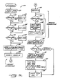
- FIG. 7A there is shown a flowchart generally designated 120 of a specific procedure for execution by the numerical processor 81 to perform the encoding process. This procedure is executed in response to the interrupt signal (from line 100 in FIG. 6) which signals that the latch 99 receives a new PCM value representing an audio sample.
- the PCM value is read from the latch 99, and also the pointer value POINT is read from the PCM bit counter 85.
- the pointer POINT is compared to zero in step 122. If POINT is zero, a few initialization functions are performed in step 123. Specifically, in step 123 memory locations MIN and MAX are set to zero. (For maximum computing speed, it is also desirable to perform step 138 in step 123 instead of at the end of the procedure.)
- step 124 the current PCM value is compared to the value MIN. If the PCM value is smaller, then in step 125 MIN is set to the value of the PCM sample. Similarly, to find the maximum PCM value in the frame, in step 126 the PCM value is compared to the value MAX. If the PCM value is larger, then in step 127 the value MAX is set equal to the value of the PCM sample. In step 128, the PCM sample is stored in the PCM buffer at the memory location indicated by the pointer POINT. Before storage, however, the pre-existing value at that location is read out and stored in a register NORM.
- step 129 the common offset value K is subtracted from the value of NORM to obtain a centered value.
- a number of left-shift operations are performed as indicated by the exponent magnitude previously determined (in step 138) for the corresponding frame.
- the exponent magnitude corresponding to the frame for the value NORM is found in the memory location EXP.
- the number of shifts is indicated by the value of a memory location SHIFT.
- the format translation operation begins in step 130 by setting the value of SHIFT to zero. Then, in step 131, the value of SHIFT is compared to the value of EXP. When they become equal, the shift operation has been completed. Otherwise, in step 132, the value of NORM is shifted left by one binary place, and the shift is indicated by incrementing the value of SHIFT by one in step 133. Execution then jumps back to step 131 to continue shifting until the required number of shifts have been performed. Then, in step 134, the translated value of NORM is transmitted to the frame buffer and specifically to the latch indicated by the value of POINT.
- step 135 Execution of the encoding procedure is completed for the current interrupt cycle, unless all of the latches 96 have been filled with new data.
- This condition is tested in step 135 by comparing the value of POINT to 15. Once the value of POINT reaches 15, then encoding for the current frame is completed in step 136 by performing a logical AND between the value of K and EXP, and outputting the result to the 16-bit latch (95 in FIG. 6) of the frame buffer. After this is done, a number of data transfers and computations are performed in step 170 to set up values corresponding to data stored in the PCM buffer (112 in FIG. 6). Specifically, the value of the newly computed maximum MAX is stored at a location P.
- a new value of the common offset is computed by arithmetically shifting right both MAX and MIN by one binary place, and adding the shifted values together to calculate a median or arithmetic mean value which is stored in the memory location K.
- the lower eight bits of the median value are truncated by performing a logical AND of the mean value with a value of FF00 (HEX).
- the value of P is decreased by the value of K to determine the centered maximum value for the frame of data in the PCM buffer. Since K was truncated, the value of P is also the centered value having the maximum magnitude. Therefore, in step 138, the exponent is determined based on the value of P.
- the exponent for representing a value in floating point is related to the range which includes the value as shown in Table I below:
- FIG. 7B there is shown a detailed portion of the flowchart for the step 138 in FIG. 7A.
- the exponent for the positive value P is found by searching through a binary decision tree which results in the selection of a particular one of the eight possible exponent values.
- step 143 the value is compared to 0800 (HEX) to split the range of positive values into halves, to 2000 (HEX) in step 144 and 0200 (HEX) in step 145 to break the halves in quarters, and finally to 4000 (HEX) in step 146, to 1000 (HEX) in step 147, to 0400 (HEX) in step 148, and to 0100 (HEX) in step 149 to select a particular one of the eight positive ranges corresponding to exponent magnitudes from 0 to 7.
- the particular value of the exponent magnitude is assigned to the memory location EXP in a particular one of steps 150 to 157.
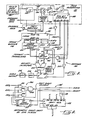
- FIG. 8 there is shown a schematic diagram of a decoder generally designated 180 for receiving and decoding data from the encoder 80 of FIG. 6. It should be apparent that the decoding process is very easily performed in comparison to the encoding process. In particular, the numerical operations are very easily performed by hard-wired logic.
- the decoder has a sync generator 181 for synchronizing the audio sample or PCM rate to the rate of the encoded data.
- the sync generator 181 operates at a master frequency set by a receiver data clock 182 operating at four times the encoded data rate.
- the receiver data clock 182 is a voltage-controlled oscillator in a conventional data clock recovery circuit (for example, in the tuner and demodulator 52 of FIG. 3). Such a data clock recovery circuit phase locks the receiver data clock 182 to the logic transitions in the encoded data.
- the sync generator 181 includes a divide by four counter to provide a signal at the encoded data rate which is used to clock a shift register 184 to receive the encoded data.
- a frame sync detector 185 which correlates data in the shift register with the predetermined 32 bit frame sync code.
- the frame sync code is a bit pattern such as ACF0FF00 (HEX) which has a sharp autocorrelation peak.
- the output Q of the flip-flop 186 is fed to a second delay flip-flop 187 clocked at four times the data rate.
- the Q output of the second flip-flop 187 is fed back to the reset input of the first flip-flop 186 in order to generate a narrow reset pulse.
- the sync generator 181 includes a PCM bit counter 188 which is clocked at the PCM bit rate and which is reset by the reset pulse from the second delay flip-flop 187.
- the signal from the receiver data clock 182 is passed through a divide-by-three counter 189 in order to clock the PCM bit counter 188 at the PCM bit rate.
- the most significant output Q8 of the PCM bit counter 188 indicates the receipt of an entire frame of encoded data into the shift register 184.
- a frame buffer 190 in the form of a 160-bit latch which is clocked in response to the Q8 output of the PCM bit counter 188.
- An inverter 192 assures that the latch is clocked to receive data from the shift register when the PCM bit counter "rolls over" to zero.
- error correction logic 194 processes the upper 16 bits from the latch 191 to obtain an error corrected exponent EXP and block offset K.
- the error correction logic 194 is provided, for example, by a programmed logic array.
- the upper eight bits from the multiplexer 183 are arithmetically right-shifted by the g35number of times indicated by the block exponent EXP.
- an arithmetic right-shift circuit 195 which is clocked at twice the PCM bit rate specified by Q0 of the PCM bit counter 188.
- the arithmetic right-shift circuit 195 is reset by a NOR gate 196 at the start of each PCM sample interval when outputs Q1, Q2 and Q3 of the PCM bit counter are all logic zeros.
- FIG. 9 there is shown a detailed schematic drawing of the arithmetic right-shift circuit generally designated 195.
- a fully synchronous counter 197 (such as a standard TTL part number 74163) is provided to indicate the number of times that a shift register 198 (such as two standard TTL part numbers 74194) has been shifted after being loaded with data values X and zero values.
- the values X are received from the multiplexer 193 in FIG. 8, and are received as the most significant eight input bits P15-P8 of the shift register 198.
- the synchronous counter 197 Upon the occurrence of a positive-going clock transition when the reset signal is a logic high, the synchronous counter 197 is reset and the data values are loaded into the shift register 198.
- the synchronous counter 197 and shift register 198 are clocked by the common clock signal, and the reset line is fed to the reset input of the synchronous counter 197, the shift left input of the shift register 198, and also, through NOR gate 199, to the shift right input of the shift register.
- the shift register 198 is of the kind Which performs a parallel load upon the occurrence of a clock transition when both its shift-left and shift-right inputs are at a logic high.
- the shift register will provide an arithmetic shift right
- its most significant output Q15 is fed to its left serial data input (DL).
- a shift right enable signal is fed to the OR gate 199.
- a numerical comparitor generally designated 200 which compares the outputs Q2-Q0 of the synchronous counter 197 to the value of the exponent.
- the numerical comparitor 200 includes exclusive-OR gates 201, 202, 203 and a NOR gate 204.
- the shift-right enable signal is therefore a logic high until the output of the synchronous counter 197 becomes equal in value to the exponent.
- the shift right enable output of the gate 204 is fed back to a clock enable (CE) input of the synchronous counter 197 to inhibit the synchronous counter 197 from counting further. Therefore, the shift register 198 performs a number of arithmetic shift-right operations specified by the exponent value, and then stops shifting.
- CE clock enable
- the translated output Y of the arithmetic right-shift circuit 195 provides a format translated value for the decoding operation.
- a binary adder 210 which computes the sum of the offset K (in the most significant eight of 16 bit positions), to the 16 bit value Y. The sum, therefore, represents the decoded PCM value.
- the output of the adder 210 is received in a 16-bit latch 211. So that the latch receives the data at the end of each PCM sample interval, the latch 211 is clocked by an inverter 212 receiving the Q3 output of PCM bit counter 188.
- parity check logic 213 such as standard TTL part number 74180.
- the output of the parity check logic enables the latch 211 in such a way that the latch is inhibited when a parity error occurs. In this fashion, each erroneous sample is replaced with the preceeding sample for which a parity error did not occur.
- the output of the latch 211 is converted to an analog signal by a digital-to-analog converter (DAC) 214, and the resulting analog signal is fed through a low pass filter 215 to remove high frequency components above the audio sampling rate, and to restore the high end of the audio spectrum from the effects of sampling.
- DAC digital-to-analog converter
- the invention provides an improved audio transmission system which is especially adapted for transmitting digitally encoded stereo audio signals over a conventional cable television channel.
- the decoder in particular, is easily fabricated from hard-wired digital logic and is therefore suitable for mass production as a custom integrated circuit.
- the encoder is more complex in comparison to the decoder, only a few encoders need be produced for each cable television system having a multitude of subscribers.
- An economical decoder therefore, insures that the digital audio transmission system of the present invention is economical to implement.
- due to the data rate compression of the present invention such a system can provide for the transmission of an increased number of audio channels over a single video channel.
- the encoding and decoding methods and apparatus of the present invention are also suitable for the recording as well as the transmission of high-fidelity audio signals.
- the present invention could also be useful for recording compressed digital audio signals on magnetic tape, since the data rate compression provided by the invention would enable such digital recording to be performed at lower tape speeds and would permit an increased amount of program material to be recorded on a tape of a given length. Similarly, a greater amount of program material in the compressed format of the invention could be stored on a magnetic or optical disc.
Landscapes
- Engineering & Computer Science (AREA)
- Theoretical Computer Science (AREA)
- Physics & Mathematics (AREA)
- Nonlinear Science (AREA)
- Compression, Expansion, Code Conversion, And Decoders (AREA)
- Transmission Systems Not Characterized By The Medium Used For Transmission (AREA)
- Signal Processing For Digital Recording And Reproducing (AREA)
- Error Detection And Correction (AREA)
Applications Claiming Priority (2)
| Application Number | Priority Date | Filing Date | Title |
|---|---|---|---|
| US07/057,370 US4922537A (en) | 1987-06-02 | 1987-06-02 | Method and apparatus employing audio frequency offset extraction and floating-point conversion for digitally encoding and decoding high-fidelity audio signals |
| US57370 | 2002-01-24 |
Publications (2)
| Publication Number | Publication Date |
|---|---|
| EP0293533A2 true EP0293533A2 (de) | 1988-12-07 |
| EP0293533A3 EP0293533A3 (de) | 1990-06-13 |
Family
ID=22010163
Family Applications (1)
| Application Number | Title | Priority Date | Filing Date |
|---|---|---|---|
| EP87309331A Withdrawn EP0293533A3 (de) | 1987-06-02 | 1987-10-22 | Verfahren und Vorrichtung mit Verschiebungsausblendung und Kompandierung für digitale Kodierung und Dekodierung von Hi-Fi-Audiosignalen |
Country Status (5)
| Country | Link |
|---|---|
| US (1) | US4922537A (de) |
| EP (1) | EP0293533A3 (de) |
| JP (1) | JPS63311826A (de) |
| AU (1) | AU598033B2 (de) |
| CA (1) | CA1308194C (de) |
Cited By (4)
| Publication number | Priority date | Publication date | Assignee | Title |
|---|---|---|---|---|
| EP0404535A3 (de) * | 1989-06-20 | 1992-08-26 | Sony Corporation | Bandbreitekompressionsgerät |
| WO1994024580A3 (en) * | 1993-04-08 | 1994-12-22 | Cambridge Consultants | Apparatus and method for displacement determination, data transfer and assessment |
| US7068211B2 (en) | 2000-02-08 | 2006-06-27 | Cambridge Consultants Limited | Methods and apparatus for obtaining positional information |
| US10154267B2 (en) | 2010-11-26 | 2018-12-11 | Nec Corporation | Video encoding device, video decoding device, video encoding method, video decoding method, and program |
Families Citing this family (52)
| Publication number | Priority date | Publication date | Assignee | Title |
|---|---|---|---|---|
| JPH0396180A (ja) * | 1989-09-08 | 1991-04-22 | Sony Corp | 受信装置 |
| JP2605916B2 (ja) * | 1990-03-19 | 1997-04-30 | ヤマハ株式会社 | 波形信号発生装置 |
| US5179576A (en) * | 1990-04-12 | 1993-01-12 | Hopkins John W | Digital audio broadcasting system |
| US5388181A (en) * | 1990-05-29 | 1995-02-07 | Anderson; David J. | Digital audio compression system |
| JPH04182700A (ja) * | 1990-11-19 | 1992-06-30 | Nec Corp | 音声認識装置 |
| US5239540A (en) * | 1990-11-27 | 1993-08-24 | Scientific-Atlanta, Inc. | Method and apparatus for transmitting, receiving and communicating digital data signals with corresponding program data signals which describe the digital data signals |
| US5253275A (en) | 1991-01-07 | 1993-10-12 | H. Lee Browne | Audio and video transmission and receiving system |
| CA2066540C (en) * | 1991-06-13 | 1998-01-20 | Edwin A. Kelley | Multiple user digital receiving apparatus and method with time division multiplexing |
| US5218639A (en) * | 1991-12-02 | 1993-06-08 | Gte Government Systems Corporation | Method and apparatus for changing bit rate of digitized analog |
| US5220602A (en) * | 1991-12-09 | 1993-06-15 | General Instrument Corporation | NICAM compatible television signal converter |
| EP0552034B1 (de) * | 1992-01-14 | 2003-04-09 | Fujitsu Limited | Gleichzeitige Übertragung von Daten und analogen Sprachbandsignalen |
| TW224191B (de) * | 1992-01-28 | 1994-05-21 | Qualcomm Inc | |
| US5272752A (en) * | 1992-03-16 | 1993-12-21 | Scientific-Atlanta, Inc. | Authorization code lockout mechanism for preventing unauthorized reception of transmitted data |
| US5271011A (en) * | 1992-03-16 | 1993-12-14 | Scientific-Atlanta, Inc. | Digital audio data muting system and method |
| US5689692A (en) * | 1992-12-23 | 1997-11-18 | Honeywell Inc. | Method and apparatus for decoding an encoded NRZ signal |
| US5787387A (en) * | 1994-07-11 | 1998-07-28 | Voxware, Inc. | Harmonic adaptive speech coding method and system |
| US5781452A (en) * | 1995-03-22 | 1998-07-14 | International Business Machines Corporation | Method and apparatus for efficient decompression of high quality digital audio |
| US5659755A (en) * | 1995-11-20 | 1997-08-19 | International Business Machines Corporation | Method and system in a data processing system for efficiently compressing data using a sorting network |
| US6038536A (en) * | 1997-01-31 | 2000-03-14 | Texas Instruments Incorporated | Data compression using bit change statistics |
| JP3459339B2 (ja) * | 1997-07-03 | 2003-10-20 | 株式会社リコー | Ppm方式を採用する変調回路、復調回路及び変復調回路システム |
| US5986589A (en) * | 1997-10-31 | 1999-11-16 | Ati Technologies, Inc. | Multi-stream audio sampling rate conversion circuit and method |
| US5963153A (en) * | 1997-10-31 | 1999-10-05 | Ati Technologies, Inc. | Multi-stream audio sampling rate conversion system and method using variable converter rate control data |
| US6167551A (en) * | 1998-07-29 | 2000-12-26 | Neomagic Corp. | DVD controller with embedded DRAM for ECC-block buffering |
| KR100926210B1 (ko) * | 1999-03-12 | 2009-11-09 | 다피모 코.비.브이.,엘엘씨 | 무중단 전송률 조정형 다중캐리어 변조 시스템 및 프로토콜 |
| US6778596B1 (en) | 1999-03-12 | 2004-08-17 | Aware, Inc. | Method and multi-carrier transceiver with stored application profiles for supporting multiple applications |
| US6396421B1 (en) * | 2001-07-31 | 2002-05-28 | Wind River Systems, Inc. | Method and system for sampling rate conversion in digital audio applications |
| US6882685B2 (en) * | 2001-09-18 | 2005-04-19 | Microsoft Corporation | Block transform and quantization for image and video coding |
| US7240001B2 (en) | 2001-12-14 | 2007-07-03 | Microsoft Corporation | Quality improvement techniques in an audio encoder |
| US6934677B2 (en) * | 2001-12-14 | 2005-08-23 | Microsoft Corporation | Quantization matrices based on critical band pattern information for digital audio wherein quantization bands differ from critical bands |
| US7502743B2 (en) | 2002-09-04 | 2009-03-10 | Microsoft Corporation | Multi-channel audio encoding and decoding with multi-channel transform selection |
| JP4676140B2 (ja) | 2002-09-04 | 2011-04-27 | マイクロソフト コーポレーション | オーディオの量子化および逆量子化 |
| JP4049791B2 (ja) * | 2003-04-28 | 2008-02-20 | 日本電信電話株式会社 | 浮動小数点形式ディジタル信号可逆符号化方法、及び復号化方法と、その各装置、その各プログラム |
| US7557862B2 (en) * | 2003-08-14 | 2009-07-07 | Broadcom Corporation | Integrated circuit BTSC encoder |
| US8718298B2 (en) * | 2003-12-19 | 2014-05-06 | Lear Corporation | NVH dependent parallel compression processing for automotive audio systems |
| US7460990B2 (en) * | 2004-01-23 | 2008-12-02 | Microsoft Corporation | Efficient coding of digital media spectral data using wide-sense perceptual similarity |
| EP1872504B1 (de) * | 2005-03-29 | 2009-07-29 | Thomson Licensing | Verfahren und vorrichtung zum verbessern des empfangs fountain kodierter signale |
| US8032240B2 (en) * | 2005-07-11 | 2011-10-04 | Lg Electronics Inc. | Apparatus and method of processing an audio signal |
| US7689052B2 (en) * | 2005-10-07 | 2010-03-30 | Microsoft Corporation | Multimedia signal processing using fixed-point approximations of linear transforms |
| US8195462B2 (en) * | 2006-02-16 | 2012-06-05 | At&T Intellectual Property Ii, L.P. | System and method for providing large vocabulary speech processing based on fixed-point arithmetic |
| US8942289B2 (en) * | 2007-02-21 | 2015-01-27 | Microsoft Corporation | Computational complexity and precision control in transform-based digital media codec |
| US7885819B2 (en) | 2007-06-29 | 2011-02-08 | Microsoft Corporation | Bitstream syntax for multi-process audio decoding |
| US8249883B2 (en) * | 2007-10-26 | 2012-08-21 | Microsoft Corporation | Channel extension coding for multi-channel source |
| US8638931B2 (en) * | 2007-10-30 | 2014-01-28 | Spansion Llc | Signal descrambling detector |
| US20090129521A1 (en) * | 2007-11-21 | 2009-05-21 | Broadcom Corporation | Systems and methods for increasing audio snr (signal to noise ratio) in a digital sound decoder |
| GB2466671B (en) | 2009-01-06 | 2013-03-27 | Skype | Speech encoding |
| GB2466675B (en) * | 2009-01-06 | 2013-03-06 | Skype | Speech coding |
| GB2466673B (en) | 2009-01-06 | 2012-11-07 | Skype | Quantization |
| US8965774B2 (en) * | 2011-08-23 | 2015-02-24 | Apple Inc. | Automatic detection of audio compression parameters |
| US20160171987A1 (en) * | 2014-12-16 | 2016-06-16 | Psyx Research, Inc. | System and method for compressed audio enhancement |
| CN109243471B (zh) * | 2018-09-26 | 2022-09-23 | 杭州联汇科技股份有限公司 | 一种快速编码广播用数字音频的方法 |
| WO2023189162A1 (ja) * | 2022-03-30 | 2023-10-05 | ソニーグループ株式会社 | 送信装置、受信装置および送受信システム |
| CN118737207B (zh) * | 2024-09-04 | 2024-11-15 | 杭州爱华智能科技有限公司 | 录音数据压缩方法和可计算幅度的录音数据解压方法 |
Family Cites Families (4)
| Publication number | Priority date | Publication date | Assignee | Title |
|---|---|---|---|---|
| US4295223A (en) * | 1979-04-25 | 1981-10-13 | Westinghouse Electric Corp. | Digital signal/noise ratio amplifier apparatus for a communication system |
| US4550425A (en) * | 1982-09-20 | 1985-10-29 | Sperry Corporation | Speech sampling and companding device |
| DE3328111A1 (de) * | 1983-08-04 | 1985-02-21 | Telefunken Fernseh Und Rundfunk Gmbh, 3000 Hannover | Quasi-momentanwert-kompander |
| JPS61123928A (ja) * | 1984-09-05 | 1986-06-11 | Hitachi Ltd | 浮動小数点データ処理装置 |
-
1987
- 1987-06-02 US US07/057,370 patent/US4922537A/en not_active Expired - Fee Related
- 1987-09-24 AU AU78947/87A patent/AU598033B2/en not_active Ceased
- 1987-10-08 CA CA000548903A patent/CA1308194C/en not_active Expired - Fee Related
- 1987-10-22 EP EP87309331A patent/EP0293533A3/de not_active Withdrawn
- 1987-12-28 JP JP62336743A patent/JPS63311826A/ja active Pending
Cited By (9)
| Publication number | Priority date | Publication date | Assignee | Title |
|---|---|---|---|---|
| EP0404535A3 (de) * | 1989-06-20 | 1992-08-26 | Sony Corporation | Bandbreitekompressionsgerät |
| WO1994024580A3 (en) * | 1993-04-08 | 1994-12-22 | Cambridge Consultants | Apparatus and method for displacement determination, data transfer and assessment |
| US7068211B2 (en) | 2000-02-08 | 2006-06-27 | Cambridge Consultants Limited | Methods and apparatus for obtaining positional information |
| US7227493B2 (en) | 2000-02-08 | 2007-06-05 | Cambridge Consultants Limited | Methods and apparatus for obtaining positional information |
| US10154267B2 (en) | 2010-11-26 | 2018-12-11 | Nec Corporation | Video encoding device, video decoding device, video encoding method, video decoding method, and program |
| US10742991B2 (en) | 2010-11-26 | 2020-08-11 | Nec Corporation | Video encoding device, video decoding device, video encoding method, video decoding method, and program |
| US11310510B2 (en) | 2010-11-26 | 2022-04-19 | Nec Corporation | Video encoding device, video decoding device, video encoding method, video decoding method, and program |
| US11659189B2 (en) | 2010-11-26 | 2023-05-23 | Nec Corporation | Video encoding device, video decoding device, video encoding method, video decoding method, and program |
| US11659188B2 (en) | 2010-11-26 | 2023-05-23 | Nec Corporation | Video encoding device, video decoding device, video encoding method, video decoding method, and program |
Also Published As
| Publication number | Publication date |
|---|---|
| EP0293533A3 (de) | 1990-06-13 |
| CA1308194C (en) | 1992-09-29 |
| JPS63311826A (ja) | 1988-12-20 |
| AU598033B2 (en) | 1990-06-14 |
| US4922537A (en) | 1990-05-01 |
| AU7894787A (en) | 1988-12-08 |
Similar Documents
| Publication | Publication Date | Title |
|---|---|---|
| US4922537A (en) | Method and apparatus employing audio frequency offset extraction and floating-point conversion for digitally encoding and decoding high-fidelity audio signals | |
| US6289308B1 (en) | Encoded wideband digital transmission signal and record carrier recorded with such a signal | |
| CN1149798C (zh) | 传送诸如环绕信号之类的附加信号的数字传送系统 | |
| US4633483A (en) | Near-instantaneous companding PCM involving accumulation of less significant bits removed from original data | |
| JPH0685509B2 (ja) | デジタルオーディオ圧伸およびエラー調節 | |
| JPS6226672A (ja) | オ−デイオ情報をデイジタル形式で伝送する方法 | |
| US4750167A (en) | Digital audio transmission system | |
| AU600137B2 (en) | Apparatus for digital signal | |
| US4491869A (en) | Pulse code modulation system suitable for digital recording of broadband analog signals | |
| US5298899A (en) | PCM encoder and decoder using exkrema | |
| US5440596A (en) | Transmitter, receiver and record carrier in a digital transmission system | |
| WO1994018762A1 (en) | Transmission of digital data words representing a signal waveform | |
| US5168116A (en) | Method and device for compressing signals of plural channels | |
| JPH0319734B2 (de) | ||
| JP2785822B2 (ja) | テレビジョン信号の高能率符号化装置及び復号装置 | |
| US5325240A (en) | Data compression and expansion apparatus for audio recorders | |
| JPH0229255B2 (ja) | Shingodensohoshiki | |
| JP2652371B2 (ja) | 音声符号化方法 | |
| JPS5866440A (ja) | 波形符号化方式 | |
| JPS6319919A (ja) | 音声符号化方式 | |
| KR960013964B1 (ko) | 다중채널 데이터 압축장치 | |
| JPS6318728A (ja) | 音声符号化方式 | |
| JPS59182639A (ja) | 信号伝送方式 | |
| JPS63205858A (ja) | 音声信号記録方式 | |
| JPH089940Y2 (ja) | ディジタル信号復号器 |
Legal Events
| Date | Code | Title | Description |
|---|---|---|---|
| PUAI | Public reference made under article 153(3) epc to a published international application that has entered the european phase |
Free format text: ORIGINAL CODE: 0009012 |
|
| AK | Designated contracting states |
Kind code of ref document: A2 Designated state(s): AT BE CH DE ES FR GB GR IT LI LU NL SE |
|
| PUAL | Search report despatched |
Free format text: ORIGINAL CODE: 0009013 |
|
| AK | Designated contracting states |
Kind code of ref document: A3 Designated state(s): AT BE CH DE ES FR GB GR IT LI LU NL SE |
|
| 17P | Request for examination filed |
Effective date: 19901212 |
|
| 17Q | First examination report despatched |
Effective date: 19920120 |
|
| STAA | Information on the status of an ep patent application or granted ep patent |
Free format text: STATUS: THE APPLICATION IS DEEMED TO BE WITHDRAWN |
|
| 18D | Application deemed to be withdrawn |
Effective date: 19930210 |
|
| RIN1 | Information on inventor provided before grant (corrected) |
Inventor name: FREDERIKSEN, JEFFREY E. |