EP0291925B1 - Bohrlochverschlussstopfen - Google Patents
Bohrlochverschlussstopfen Download PDFInfo
- Publication number
- EP0291925B1 EP0291925B1 EP88107872A EP88107872A EP0291925B1 EP 0291925 B1 EP0291925 B1 EP 0291925B1 EP 88107872 A EP88107872 A EP 88107872A EP 88107872 A EP88107872 A EP 88107872A EP 0291925 B1 EP0291925 B1 EP 0291925B1
- Authority
- EP
- European Patent Office
- Prior art keywords
- head
- closure
- inlet
- outlet
- borehole
- Prior art date
- Legal status (The legal status is an assumption and is not a legal conclusion. Google has not performed a legal analysis and makes no representation as to the accuracy of the status listed.)
- Expired - Lifetime
Links
- 239000007788 liquid Substances 0.000 claims abstract description 14
- 239000011435 rock Substances 0.000 claims abstract description 3
- 238000007789 sealing Methods 0.000 claims description 9
- 239000012530 fluid Substances 0.000 claims 1
- 238000005065 mining Methods 0.000 abstract description 4
- 230000006641 stabilisation Effects 0.000 abstract 1
- 238000011105 stabilization Methods 0.000 abstract 1
- 125000006850 spacer group Chemical group 0.000 description 28
- 239000004033 plastic Substances 0.000 description 9
- 229920003023 plastic Polymers 0.000 description 9
- 230000006835 compression Effects 0.000 description 4
- 238000007906 compression Methods 0.000 description 4
- 210000002445 nipple Anatomy 0.000 description 3
- 230000006378 damage Effects 0.000 description 2
- 230000000694 effects Effects 0.000 description 2
- 239000006260 foam Substances 0.000 description 2
- 239000006261 foam material Substances 0.000 description 2
- 238000004519 manufacturing process Methods 0.000 description 2
- 239000000463 material Substances 0.000 description 2
- 238000011144 upstream manufacturing Methods 0.000 description 2
- 230000004323 axial length Effects 0.000 description 1
- 230000000903 blocking effect Effects 0.000 description 1
- 238000006243 chemical reaction Methods 0.000 description 1
- 229920001971 elastomer Polymers 0.000 description 1
- 238000005516 engineering process Methods 0.000 description 1
- 238000002347 injection Methods 0.000 description 1
- 239000007924 injection Substances 0.000 description 1
- 238000001746 injection moulding Methods 0.000 description 1
- 238000003780 insertion Methods 0.000 description 1
- 230000037431 insertion Effects 0.000 description 1
- 230000001788 irregular Effects 0.000 description 1
- 239000002184 metal Substances 0.000 description 1
- 238000000034 method Methods 0.000 description 1
- 229920002635 polyurethane Polymers 0.000 description 1
- 239000004814 polyurethane Substances 0.000 description 1
- 238000010944 pre-mature reactiony Methods 0.000 description 1
- 230000036316 preload Effects 0.000 description 1
- 238000003825 pressing Methods 0.000 description 1
- 230000000717 retained effect Effects 0.000 description 1
- 239000007787 solid Substances 0.000 description 1
- 238000007711 solidification Methods 0.000 description 1
- 230000008023 solidification Effects 0.000 description 1
- 239000000243 solution Substances 0.000 description 1
Images

Classifications
-
- E—FIXED CONSTRUCTIONS
- E21—EARTH OR ROCK DRILLING; MINING
- E21B—EARTH OR ROCK DRILLING; OBTAINING OIL, GAS, WATER, SOLUBLE OR MELTABLE MATERIALS OR A SLURRY OF MINERALS FROM WELLS
- E21B33/00—Sealing or packing boreholes or wells
- E21B33/10—Sealing or packing boreholes or wells in the borehole
- E21B33/12—Packers; Plugs
- E21B33/127—Packers; Plugs with inflatable sleeve
Definitions
- the invention relates to an expandable, lost closure plug for boreholes to be filled with liquid under pressure for rock solidification in underground mining with an elastic, tubular, derived from the liquid pressure automatically tensioning against the borehole wall, extending between an inlet and an outlet head, the rigid piece Surrounds spacer between the inlet and outlet head, wherein a flow channel for the liquid extends through the inlet and outlet head and continues in the spacer up to a mouth in the area between the closure piece and the spacer.
- a borehole closure of this type is known from DE-C-30 14 834.
- the spacer is tubular and thus represents a direct connection between the flow channels in the inlet and outlet heads.
- the preloading the valve at the outlet head is greater than the preload of the valve at the inlet head, so that when the pressurized liquid flows into the spacer, the liquid flows through the orifices in the spacer also penetrates into the space between the spacer and the closure piece and a total pressure builds up in the interior of the closure plug before opening the valve on the outlet head, which spreads the closure piece and presses it firmly against the borehole wall.
- the borehole closure is preferably made of plastic.
- it In order to enable a secure jamming of the sealing plug, it must have a certain minimum length - also taking into account an irregular borehole surface.
- the borehole closure must withstand a pressure of 60 to 90 bar.
- the spacer is also exposed to a correspondingly high pressure load. It has now been shown in practice that, starting from the usual borehole diameters of approximately 42 to 44 mm and the required axial length of the borehole closure and the resulting ratio of diameter and length, a tubular spacer of sufficient strength as an inexpensive plastic injection-molded part can hardly be produced in terms of production technology is.
- pumps are used in the pressing of plastic components as conveying means, which feed the individual components to the borehole closure in separate pump cylinders and separate lines in order to prevent a premature reaction.
- a process-specific reaction for example of the components of polyurethane, is an intensive one Assuming mixing, an additional mixer must be installed upstream of the borehole plug.
- the invention has for its object to design the sealing plug described in such a way that on the one hand the intensive mixing of the plastic components in the sealing plug itself can take place without additional cost, so that separate mixing devices to be arranged between the pumps and the sealing plug can be dispensed with, and the spacer as simple plastic injection molded part in a design that meets all requirements should be retained.
- the liquid comprising the plastic components and pressed through the sealing plug into the borehole undergoes a multiple deflection.
- Even the double deflection following the inlet head corresponds to the function of a conventional swirler.
- the double redirection in front of the outlet head further intensifies the homogeneous mixing of the plastic components.
- the plug thus also takes on the function of the otherwise usual mixing device and comes in the intensity of the mixing effect the usual Swirl immediately, without the sealing plug even having an additional component.
- the spacer can be made solid over the major part of its length, so that the injection-molding problems during manufacture are eliminated and the spacer is able to withstand all loads that occur .
- An expedient embodiment consists in that the channels in the spacer initially extend from its ends in its longitudinal direction and then merge into a mouth section angled with respect to this longitudinal direction, a further expedient embodiment consisting in that the mouth section each crosswise through one in the spacer whose longitudinal direction arranged opening is formed.
- the borehole closure designated as a whole by 10, comprises an expandable closure piece 16, which is arranged between two valve heads, designated as inlet head 12 and outlet head 14, and which is designed as a high-pressure-resistant rubber hose, the diameter of which, when unloaded, is slightly smaller than the diameter of the borehole to be closed, the diameter of the borehole for example, can be 45 mm.
- the two valve heads 12 and 14 consist essentially of basic bodies 18 and 20 which are rotationally symmetrical with respect to the hose axis and which are traversed by a central channel 22 and 24.
- the base bodies 18 and 20 each have a tubular section 26 and 28 which is provided with an internal thread 30 and 32 and in which the end of a spacer provided with a corresponding external thread 34 and 36 38 is screwed in, which serves to hold the two valve heads 12 and 14 at a predetermined distance, in which the closure piece 16 is stretched so that it can be easily inserted into the borehole by means of a feed pipe or hose.
- the end sections 44 and 46 of the closure piece 16 are drawn onto the outer surfaces 40 or 42 of the tubular sections 26 and 28, which are overlapped by clamping sleeves 48 and 50 formed on the base bodies 18 and 20.
- the two valve heads 12 and 14 are designed differently with respect to the valve arrangement depending on the flow direction provided.
- the foam material to be filled into the borehole must be pressed into the borehole through the borehole closure 10.
- a filling line 52 is connected to the inlet head 12 adjacent to the mouth of the borehole.
- the base body 18 is provided in its end section facing away from the closure piece 16 with an internal thread 54, on the inner end of which a shoulder 56 is formed which surrounds a valve opening 59.
- a seal 58 is arranged on the shoulder 56.
- a conical valve seat 60 is formed on the other side of the valve opening 59, to which a valve ball 62 is assigned, which is pressed against the valve seat 60 by a compression spring 64.
- the compression spring 64 is supported on the end of the spacer 38 inserted into the base body 18.
- a valve opening 66 is also provided on the outlet head 14, again on the downstream one On the side of this valve opening 66, now on the side facing away from the spacer 38, a valve seat 68 is formed, to which a valve ball 70 is assigned, which is pressed against the valve seat 68 by a compression spring 72.
- the compression spring 72 is supported on a nipple 74 which is screwed into an internal thread 76 which is formed on the end section of the base body 20 which faces away from the closure piece 16.
- the action of the spring 72 can be adjusted, the force of which is in any case greater than the force of the spring 64 in the inlet head 12, so that in the initial phase of the introduction of the pressurized foam, the closure piece 16 is first spread before the foam can escape into the borehole.
- the nipple 74 is provided with a bore 78 for the passage of the foam material into the borehole.
- the spacer 38 is at its two ends 80 and 82 each with a central channel 84 running in the longitudinal direction of the spacer 38 or 86, which extends within the spacer 38 in each case up to an aperture 88 or 90 which diametrically crosses the spacer.
- These openings 88 and 90 represent the connection between the channels 80 and 82 and the annular space between the closure piece 16 and the spacer 38.
- the spacer 38 In the area between the two openings 88 and 90, the spacer 38 preferably has a cross-shaped cross-sectional shape, which results in a material saving while maintaining the required rigidity.
- the described borehole closure 10 has a simple and inexpensive design and can be handled very easily.
- the borehole plug must be inserted into the borehole with the valve head 14 in front of it, whereupon the connecting line between the pumps and the borehole plug 10 must be connected and removed after the borehole has been filled.
Landscapes
- Life Sciences & Earth Sciences (AREA)
- Engineering & Computer Science (AREA)
- Geology (AREA)
- Mining & Mineral Resources (AREA)
- Physics & Mathematics (AREA)
- Environmental & Geological Engineering (AREA)
- Fluid Mechanics (AREA)
- General Life Sciences & Earth Sciences (AREA)
- Geochemistry & Mineralogy (AREA)
- Consolidation Of Soil By Introduction Of Solidifying Substances Into Soil (AREA)
- Investigation Of Foundation Soil And Reinforcement Of Foundation Soil By Compacting Or Drainage (AREA)
- Pressure Vessels And Lids Thereof (AREA)
Description
- Die Erfindung betrifft einen aufweitbaren, verlorenen Verschlußstopfen für unter Druck mit Flüssigkeit zu verfüllende Bohrlöcher zur Gesteinsverfestigung im Untertagebergbau mit einem elastischen, schlauchförmigen, sich abgeleitet vom Flüssigkeitsdruck selbsttätig gegen die Bohrlochwandung verspannenden, sich zwischen einem Einlaß- und einem Auslaßkopf erstreckenden Verschlußstück, das ein starres Distanzstück zwischen Einlaß- und Auslaßkopf umgibt, wobei sich durch den Einlaß- und Auslaßkopf jeweils ein Strömungskanal für die Flüssigkeit erstreckt und sich im Distanzstück bis zu jeweils einer Ausmündung in den Bereich zwischen dem Verschlußstück und dem Distanzstück fortsetzt.
- Ein Bohrlochverschluß dieser Art ist aus der DE-C-30 14 834 bekannt. Bei dem bekannten Verschlußstopfen ist das Distanzstück rohrförmig ausgebildet und stellt somit eine direkte Verbindung zwischen den Strömungskanälen im Einlaß- und im Auslaßkopf dar. Im Bereich des Einlaß- und des Auslaßkopfs sind jeweils entgegen der Füllrichtung vorgespannte und sperrende Rückschlagventile vorgesehen, wobei die Vorspannung das Ventils am Auslaßkopf größer ist als die Vorspannung des Ventils am Einlaßkopf, so daß beim Einströmen der unter Druck stehenden Flüssigkeit in das Distanzstück die Flüssigkeit über die Ausmündungen im Distanzstück auch in den Raum zwischen Distanzstück und Verschlußstück eindringt und sich insgesamt im Inneren des Verschlußstopfens vor dem öffnen des Ventlls am Auslaßkopf ein Druck aufbaut, der das Verschlußstück spreizt und fest gegen die Bohrlochwandung preßt.
- Um spätere Beschädigungen von Abbauwerkzeugen und eine Verletzug von Personen durch gegebenenfalls von Abbauwerkzeugen gelöste und von ihnen aus dem Arbeitsbereich geschleuderte Metallstücke zu vermeiden, wird der Bohrlochverschluß vorzugsweise aus Kunststoff gefertigt. Um ein sicheres Verklemmen des Verschlußstopfens zu ermöglichen, muß er - auch unter Berücksichtigung einer unregelmäßigen Bohrlochoberfläche - eine gewisse Mindestlänge aufweisen. Dabei muß der Bohrlochverschluß einem Preßdruck von 60 bis 90 bar standhalten. Auch das Distanzstück ist einer entsprechend hohen Druckbelastung ausgesetzt. Es hat sich nun in der Praxis gezeigt, daß, ausgehend von den üblichen Bohrlochdurchmessern von etwa 42 bis 44 mm und der erforderlichen axialen Länge des Bohrlochverschlusses und des dadurch gegebenen Verhältnisses von Durchmesser und Länge, ein rohrförmiges Distanzstück ausreichender Festigkeit als billiges Kunststoffspritzteil fertigungstechnisch kaum herstellbar ist.
- Zur Zeit werden bei der Verpressung von Kunststoffkomponenten als Fördermittel Pumpen eingesetzt, welche die einzelnen Komponenten in getrennten Pumpenzylindern und getrennten Leitungen dem Bohrlochverschluß zuführen, um eine vorzeitige Reaktion zu verhindern. Da eine verfahrensspezifische Reaktion beispielsweise der Komponenten von Polyurethan eine intensive Vermischung voraussetzt, muß dem Bohrlochverschluß unbedingt ein zusätzlicher Mischer vorgeschaltet werden.
- Der Erfindung liegt die Aufgabe zugrunde, den eingangs beschriebenen Verschlußstopfen derart auszugestalten, daß ohne zusätzlichen Kostenaufwand einerseits die intensive Vermischung der Kunststoffkomponenten im Verschlußstopfen selbst stattfinden kann, so daß gesonderte, zwischen den Pumpen und den Verschlußstopfen anzuordnende Mischvorrichtungen entfallen können, wobei außerdem das Distanzstück als einfaches Kunststoffspritzteil in einer allen Anforderungen gerecht werdenden Ausführung beibehalten werden soll.
- Die Lösung dieser Aufgabe besteht darin, daß sich die Strömungskanäle des Einlaß- und des Auslaßkopfs im Distanzstück nur in dessen Endabschnitten jeweils bis zu einer dem Einlaß- bzw. Auslaßkopf benachbarten Ausmündung in den Bereich zwischen dem Verschlußstück und dem Distanzstück fortsetzen.
- Durch diese Ausgestaltung des Verschlußstopfens erfährt die durch den Verschlußstopfen in das Bohrloch gepreßte, die Kunststoffkomponenten umfassende Flüssigkeit eine mehrfache Umlenkung. Bereits die doppelte Umlenkung im Anschluß an den Einlaßkopf entspricht der Funktion eines üblichen Verwirblers. Die erneute doppelte Um-lenkung vor dem Auslaßkopf intensiviert die homogene Durchmischung der Kunststoffkomponenten zusätzlich. Der Verschlußstopfen übernimmt also zugleich die Funktion der sonst üblichen Mischvorrichtung und kommt in der Intensität der Mischwirkung den üblichen Verwirblern gleich, ohne daß der Verschlußstopfen auch nur ein zusätzliches Bauteil aufweist.
- Da der Strömungsweg der Flüssigkeit zwischen Einlaß- und Auslaßkopf über die Blähkammer zwischen Distanzstück und Verschlußstück geführt wird, kann das Distanzstück über den wesentlichen Teil seiner Länge massiv ausgebildet werden, so daß die spritztechnischen Probleme bei der Fertigung entfallen und das Distanzstück allen auftretenden Belastungen gewachsen ist.
- Eine zweckmäßige Ausgestaltung besteht darin, daß sich die Kanäle im Distanzstück von dessen Enden her zunächst in dessen Längsrichtung erstrecken und dann in einen gegenüber dieser Längsrichtung abgewinkelten Mündungsabschnitt übergehen, wobei eine weitere zweckmäßige Ausgestaltung darin besteht, daß der Mündungsabschnitt jeweils durch eine im Distanzstück quer zu dessen Längsrichtung angeordnete Durchbrechung gebildet wird. Dadurch wird der Flüssigkeitsstrom nach dem Einlaßkopf in zwei nach entgegengesetzter Richtung umgelenkte Teilströme aufgeteilt, die sich vor dem Auslaßkopf wieder vereinigen, wodurch eine weitere Verbesserung der Mischwirkung erzielt wird.
- Weitere zweckmäßige Ausgestaltungen der Erfindung ergeben sich aus den Unteransprüchen in Verbindung mit der nachfolgenden Beschreibung.
- Anhand der nachfolgenden Beschreibung eines in der Zeichnung dargestellten Ausführungsbeispiels der Erfindung wird diese näher erläutert.
- Es zeigt:
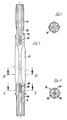
- Fig. 1
- einen Längsschnitt durch einen erfindungsgemäßen Verschlußstopfen vor dem Einführen in das Bohrloch,
- Fig. 2
- eine Seitenansicht dazu in Klemmstellung,
- Fig. 3
- einen Längsschnitt durch das Distanzstück,
- Fig. 4
- einen Schnitt nach der Linie IV-IV in Fig. 3 und
- Fig. 5
- einen Schnitt nach der Linie V-V in Fig. 3.
- Der insgesamt mit 10 bezeichnete Bohrlochverschluß umfaßt ein zwischen zwei als Einlaßkopf 12 und Auslaßkopf 14 bezeichneten Ventilköpfen angeordnetes, aufweitbares Verschlußstück 16, welches als hochdruckfester Gummischlauch ausgebildet ist, dessen Durchmesser in unbelastetem Zustand etwas geringer ist, als der Durchmesser des zu verschließenden Bohrlochs, dessen Durchmesser beispielsweise 45 mm betragen kann.
- Die beiden Ventilköpfe 12 und 14 bestehen aus im wesentlichen zur Schlauchachse rotationssymmetrischen Grundkörpern 18 bzw. 20, die von einem zentralen Kanal 22 bzw. 24 durchzogen werden. Auf der dem Verschlußstück 16 zugewandten Seite weisen die Grundkörper 18 bzw. 20 jeweils einen rohrförmigen Abschnitt 26 bzw. 28 auf, der mit einem Innengewinde 30 bzw. 32 versehen ist und in welchen das mit einem entsprechenden Außengewinde 34 bzw. 36 versehene Ende eines Distanzstücks 38 eingeschraubt ist, welches dazu dient, die beiden Ventilköpfe 12 und 14 in einem vorgegebenen Abstand zu halten, in welchem das Verschlußstück 16 gestreckt ist, so daß es sich leicht mittels eines Beschickungsrohrs oder eines Schlauchs in das Bohrloch einsetzen läßt. Auf die Außenflächen 40 oder 42 der rohrförmigen Abschnitte 26 bzw. 28 sind die Endabschnitte 44 bzw. 46 des Verschlußstücks 16 aufgezogen, welche von an den Grundkörpern 18 und 20 angeformten Klemmhülsen 48 bzw. 50 übergriffen werden.
- Die beiden Ventilköpfe 12 und 14 sind hinsichtlich der Ventilanordnung in Abhängigkeit von der vorgesehenen Durchströmrichtung unterschiedlich gestaltet. Wenn der Bohrlochverschluß 10 in das zu verschließende Bohrloch eingesetzt ist, muß das in das Bohrloch einzufüllende Schaummaterial durch den Bohrlochverschluß 10 hindurch in das Bohrloch eingepreßt werden. Dazu wird an den der Ausmündung des Bohrlochs benachbarten Einlaßkopf 12 eine Fülleitung 52 angeschlossen. Der Grundkörper 18 ist zu diesem Zweck in seinem vom Verschlußstück 16 abgewandten Endabschnitt mit einem Innengewinde 54 versehen, an dessen innerem Ende eine Schulter 56 ausgebildet ist, die eine Ventilöffnung 59 umgibt. Auf der Schulter 56 ist eine Dichtung 58 angeordnet. In Durchströmrichtung stromab, also in Richtung auf den Auslaßkopf 14, ist auf der anderen Seite der Ventilöffnung 59 ein konischer Ventilsitz 60 ausgebildet, dem eine Ventilkugel 62 zugeordnet ist, welche durch eine Druckfeder 64 gegen den Ventilsitz 60 gedrückt wird. Die Druckfeder 64 stützt sich auf das Ende des in den Grundkörper 18 eingesetzten Distanzstücks 38 ab.
- Am Auslaßkopf 14 ist ebenfalls eine Ventilöffnung 66 vorgesehen, wobei wieder auf der stromab gelegenen Seite dieser Ventilöffnung 66, nun also auf der vom Distanzstück 38 abgewandten Seite, ein Ventilsitz 68 ausgebildet ist, dem eine Ventilkugel 70 zugeordnet ist, die durch eine Druckfeder 72 gegen den Ventilsitz 68 gedrückt wird. Die Druckfeder 72 stützt sich auf einen Nippel 74 ab, der in ein Innengewinde 76 eingeschraubt ist, das an dem vom Verschlußstück 16 abgewandten Endabschnitt des Grundkörpers 20 ausgebildet ist. Durch Verstellen des Nippels 74 kann die Wirkung der Feder 72 eingestellt werden, deren Kraft jedenfalls größer ist als die Kraft der Feder 64 im Einlaßkopf 12, damit in der Anfangsphase der Einleitung des unter Druck stehenden Schaumstoffs zunächst das Verschlußstück 16 gespreizt wird, bevor der Schaumstoff in das Bohrloch austreten kann. Für den Durchtritt des Schaummaterials in das Bohrloch ist der Nippel 74 mit einer Bohrung 78 versehen.
- Damit das über den Ventilkopf 12 und dessen Ventilöffnung 58 dem Bohrlochverschluß 10 zugeführte Material den Bohrlochverschluß 10 durchströmen und das Verschlußstück 16 spreizen kann, ist das Distanzstück 38 an seinen beiden Enden 80 und 82 jeweils mit einem zentralen, in Längsrichtung des Distanzstücks 38 verlaufenden Kanal 84 bzw. 86 versehen, der sich innerhalb des Distanzstücks 38 jeweils bis zu einer das Distanzstück diametral durchquerenden Durchbrechung 88 bzw. 90 erstreckt. Diese Druchbrechungen 88 und 90 stellen die Verbindung zwischen den Kanälen 80 bzw. 82 und dem Ringraum zwischen dem Verschlußstück 16 und dem Distanzstück 38 dar.
- In dem zwischen den beiden Durchbrechungen 88 und 90 gelegenen Bereich weist das Distanzstück 38 vorzugsweise eine kreuzförmige Querschnittsform auf, wodurch sich unter Beibehaltung der erforderlichen Steifigkeit eine Materialeinsparung ergibt.
- Durch die beschriebene Ausgestaltung des Distanzstücks 38 kann dies in kostengünstiger Weise als Kunststoffspritzteil hergestellt werden. Außerdem werden die in den Bohrlochverschluß eingeleiteten, flüssigen Kunststoffkomponenten beim Durchqueren des Bohrlochverschlusses 10 mehrmals umgelenkt und erfahren dadurch eine intensive, homogene Durchmischung, wodurch die Vorschaltung gesonderter Mischeinrichtungen vor den Bohrlochverschluß entfallen kann.
- Der beschriebene Bohrlochverschluß 10 weist eine einfache und kostengünstige Gestaltung auf und kann denkbar einfach gehandhabt werden. Der Bohrlochverschluß muß mit dem Ventilkopf 14 voraus in das Bohrloch eingeschoben werden, worauf dann die Verbindungsleitung zwischen den Pumpen und dem Bohrlochverschluß 10 angeschlossen und nach dem Füllen des Bohrlochs wieder entfernt werden muß.
Claims (5)
- Aufweitbarer, verlorener Verschlußstopfen (10) für unter Druck mit Flüssigkeit zu verfüllende Bohrlöcher zur Gesteinsverfestigung im Untertagebergbau, mit einem elastischen, schlauchförmigen, sich abgeleitet vom Flüssigkeitsdruck selbsttätig gegen die Bohrlochwandung verspannenden, sich zwischen einem Einlaß- (12) und einem Auslaßkopf (14) erstreckenden Verschlußstück (16), das ein starres Distanzstück (38) zwischen Einlaß- (12) und Auslaßkopf (14) umgibt, wobei sich durch den Einlaß- (12) und den Auslaßkopf (14) jeweils ein Strömungskanal (22, 24) für die Flüssigkeit erstreckt und sich im Distanzstück (38) bis zu jeweils einer Ausmündung (88, 90) in den Bereich zwischen dem Verschlußstück (16) und dem Distanzstück (38) fortsetzt, dadurch gekennzeichnet, daß sich die Strömungskanäle (22, 24) des Einlaß- (12) und des Auslaßkopfs (14) im Distanzstück (38) nur in dessen Endabschnitten (80, 82) jeweils bis zu einer dem Einlaß- (12) bzw. Auslaßkopf (14) benachbarten Ausmündung (88, 90) in den Bereich zwischen dem Verschlußstück (16) und dem Distanzstück (38) fortsetzen.
- Verschlußstopfen nach Anspruch 1, dadurch gekennzeichnet, daß sich die Kanäle (84, 86) im Distanzstück (38) von dessen Enden her zunächst in dessen Längsrichtung erstrecken und dann in einen gegenüber dieser Längsrichtung abgewinkelten Mündungsabschnitt (88, 90) übergehen.
- Verschlußstopfen nach Anspruch 2, dadurch gekennzeichnet, daß der Mündungsabschnitt jeweils durch eine im Distanzstück (38) quer zu dessen Längsrichtung angeordnete Durchbrechung (88, 90) gebildet wird.
- Verschlußstopfen nach Anspruch 3, dadurch gekennzeichnet, daß die Durchbrechungen (88, 90) als diametral verlaufende Längsschlitze ausgebildet sind.
- Verschlußstopfen nach einem der vorhergehenden Ansprüche, dadurch gekennzeichnet, daß das Distanzstück (38) im Bereich zwischen den Ausmündungen (88, 90) einen kreuzförmigen Querschnitt aufweist.
Priority Applications (1)
| Application Number | Priority Date | Filing Date | Title |
|---|---|---|---|
| AT88107872T ATE85400T1 (de) | 1987-05-19 | 1988-05-17 | Bohrlochverschlussstopfen. |
Applications Claiming Priority (2)
| Application Number | Priority Date | Filing Date | Title |
|---|---|---|---|
| DE3716783 | 1987-05-19 | ||
| DE19873716783 DE3716783A1 (de) | 1987-05-19 | 1987-05-19 | Bohrlochverschlussstopfen |
Publications (2)
| Publication Number | Publication Date |
|---|---|
| EP0291925A1 EP0291925A1 (de) | 1988-11-23 |
| EP0291925B1 true EP0291925B1 (de) | 1993-02-03 |
Family
ID=6327883
Family Applications (1)
| Application Number | Title | Priority Date | Filing Date |
|---|---|---|---|
| EP88107872A Expired - Lifetime EP0291925B1 (de) | 1987-05-19 | 1988-05-17 | Bohrlochverschlussstopfen |
Country Status (3)
| Country | Link |
|---|---|
| EP (1) | EP0291925B1 (de) |
| AT (1) | ATE85400T1 (de) |
| DE (2) | DE3716783A1 (de) |
Families Citing this family (3)
| Publication number | Priority date | Publication date | Assignee | Title |
|---|---|---|---|---|
| CN102071962B (zh) * | 2010-12-24 | 2012-10-24 | 中国矿业大学 | 一种下行孔封孔方法 |
| CN103693620A (zh) * | 2013-12-18 | 2014-04-02 | 常熟振氟新材料有限公司 | 从氯气与氯化氢混合气体中分离回收氯气的装置 |
| CN109209476B (zh) * | 2018-10-12 | 2021-07-20 | 中煤科工集团重庆研究院有限公司 | 导气增压装置 |
Family Cites Families (4)
| Publication number | Priority date | Publication date | Assignee | Title |
|---|---|---|---|---|
| DE1171377B (de) * | 1959-11-02 | 1964-06-04 | Dipl Berging Albrecht Graefer | Bohrtraenkverfahren und Bohrtraenkgeraet |
| DE2903137C3 (de) * | 1979-01-27 | 1982-02-18 | Bergwerksverband Gmbh, 4300 Essen | Rohrförmiger verlorener Bohrlochverschluß |
| DE3014834C2 (de) * | 1980-04-17 | 1985-09-12 | Thermoplast & Apparatebau Gmbh, 6270 Idstein | Bohrlochverschlußstopfen |
| DE3313852C1 (de) * | 1983-04-16 | 1984-11-15 | Diehl GmbH & Co, 8500 Nürnberg | Aufweitbarer, verlorener Verschlußstopfen für Injektions-Bohrlöcher |
-
1987
- 1987-05-19 DE DE19873716783 patent/DE3716783A1/de active Granted
-
1988
- 1988-05-17 EP EP88107872A patent/EP0291925B1/de not_active Expired - Lifetime
- 1988-05-17 AT AT88107872T patent/ATE85400T1/de not_active IP Right Cessation
- 1988-05-17 DE DE8888107872T patent/DE3878029D1/de not_active Expired - Fee Related
Also Published As
| Publication number | Publication date |
|---|---|
| DE3878029D1 (de) | 1993-03-18 |
| DE3716783C2 (de) | 1991-01-03 |
| EP0291925A1 (de) | 1988-11-23 |
| ATE85400T1 (de) | 1993-02-15 |
| DE3716783A1 (de) | 1988-12-15 |
Similar Documents
| Publication | Publication Date | Title |
|---|---|---|
| DE2709386C2 (de) | Drosselrückschlagventil | |
| EP0461212B1 (de) | Elektrisch gesteuerte kraftstoffeinspritzpumpe für brennkraftmaschinen, insbesondere pumpendüse | |
| DE3819305C2 (de) | ||
| DE2135346A1 (de) | Austeilerventil zur Abgabe zwei ver schiedener Flüssigkeiten aus einem Aerosolbehälter | |
| DE2215605A1 (de) | Austeiler ventil für Aerosolbehälter | |
| DE3014834C2 (de) | Bohrlochverschlußstopfen | |
| DE10155931A1 (de) | Vulkanisationsform zur Herstellung technischer Gummiprodukte | |
| CH670961A5 (de) | ||
| DE19720913C1 (de) | Kraftstoffeinspritzsystem mit gemeinsamem Vorspeicher | |
| DE19503445C2 (de) | Hydraulisch dämpfendes Lager | |
| EP0291925B1 (de) | Bohrlochverschlussstopfen | |
| EP1043496B1 (de) | Einspritzventil zur Kraftstoffeinspritzung in einer Verbrennungskraftmaschine | |
| DE19614446C1 (de) | Fettpresse | |
| DE8214927U1 (de) | Blockventil | |
| DE10020157A1 (de) | Vorrichtung zum Herstellen eines Massivstoff oder Schaumstoff bildenden Reaktionsgemisches aus mindestens zwei fließfähigen Reaktionskomponenten und gegebenenfalls Zusatzkomponenten | |
| DE4319269C2 (de) | Einspritzleitungsanschluß | |
| EP1179649A2 (de) | Injektionsbefestigungsanker | |
| WO1984001601A1 (fr) | Ancre d'injection | |
| DE3342213A1 (de) | Kraftstoffeinspritzduese | |
| DE8707207U1 (de) | Bohrlochverschlußstopfen | |
| DE3716784C2 (de) | ||
| DE1230612B (de) | Kraftstoffeinspritzventil mit schaftfoermigem Ventilkoerper | |
| DE4033814A1 (de) | Vorrichtung zur injektion von druckluft in einer fluessigkeit | |
| DE4220813C2 (de) | Anordnung zur Verbindung eines Rohres mit einem Anschlußelement | |
| DE19901850A1 (de) | Verfahren zum Herstellen einer Sanitärarmatur und Sanitärarmatur |
Legal Events
| Date | Code | Title | Description |
|---|---|---|---|
| PUAI | Public reference made under article 153(3) epc to a published international application that has entered the european phase |
Free format text: ORIGINAL CODE: 0009012 |
|
| AK | Designated contracting states |
Kind code of ref document: A1 Designated state(s): AT BE CH DE ES FR GB GR IT LI LU NL SE |
|
| 17P | Request for examination filed |
Effective date: 19890522 |
|
| 17Q | First examination report despatched |
Effective date: 19900608 |
|
| GRAA | (expected) grant |
Free format text: ORIGINAL CODE: 0009210 |
|
| AK | Designated contracting states |
Kind code of ref document: B1 Designated state(s): AT BE CH DE ES FR GB GR IT LI LU NL SE |
|
| PG25 | Lapsed in a contracting state [announced via postgrant information from national office to epo] |
Ref country code: IT Free format text: LAPSE BECAUSE OF FAILURE TO SUBMIT A TRANSLATION OF THE DESCRIPTION OR TO PAY THE FEE WITHIN THE PRESCRIBED TIME-LIMIT;WARNING: LAPSES OF ITALIAN PATENTS WITH EFFECTIVE DATE BEFORE 2007 MAY HAVE OCCURRED AT ANY TIME BEFORE 2007. THE CORRECT EFFECTIVE DATE MAY BE DIFFERENT FROM THE ONE RECORDED. Effective date: 19930203 Ref country code: BE Effective date: 19930203 Ref country code: ES Free format text: THE PATENT HAS BEEN ANNULLED BY A DECISION OF A NATIONAL AUTHORITY Effective date: 19930203 Ref country code: NL Effective date: 19930203 Ref country code: GR Free format text: LAPSE BECAUSE OF FAILURE TO SUBMIT A TRANSLATION OF THE DESCRIPTION OR TO PAY THE FEE WITHIN THE PRESCRIBED TIME-LIMIT Effective date: 19930203 Ref country code: SE Effective date: 19930203 |
|
| REF | Corresponds to: |
Ref document number: 85400 Country of ref document: AT Date of ref document: 19930215 Kind code of ref document: T |
|
| REF | Corresponds to: |
Ref document number: 3878029 Country of ref document: DE Date of ref document: 19930318 |
|
| PG25 | Lapsed in a contracting state [announced via postgrant information from national office to epo] |
Ref country code: LU Free format text: LAPSE BECAUSE OF NON-PAYMENT OF DUE FEES Effective date: 19930531 |
|
| ET | Fr: translation filed | ||
| GBT | Gb: translation of ep patent filed (gb section 77(6)(a)/1977) |
Effective date: 19930507 |
|
| NLV1 | Nl: lapsed or annulled due to failure to fulfill the requirements of art. 29p and 29m of the patents act | ||
| PLBE | No opposition filed within time limit |
Free format text: ORIGINAL CODE: 0009261 |
|
| STAA | Information on the status of an ep patent application or granted ep patent |
Free format text: STATUS: NO OPPOSITION FILED WITHIN TIME LIMIT |
|
| 26N | No opposition filed | ||
| PGFP | Annual fee paid to national office [announced via postgrant information from national office to epo] |
Ref country code: GB Payment date: 19970509 Year of fee payment: 10 |
|
| PGFP | Annual fee paid to national office [announced via postgrant information from national office to epo] |
Ref country code: FR Payment date: 19970514 Year of fee payment: 10 |
|
| PGFP | Annual fee paid to national office [announced via postgrant information from national office to epo] |
Ref country code: CH Payment date: 19970528 Year of fee payment: 10 Ref country code: DE Payment date: 19970528 Year of fee payment: 10 |
|
| PGFP | Annual fee paid to national office [announced via postgrant information from national office to epo] |
Ref country code: AT Payment date: 19970531 Year of fee payment: 10 |
|
| PG25 | Lapsed in a contracting state [announced via postgrant information from national office to epo] |
Ref country code: AT Free format text: LAPSE BECAUSE OF NON-PAYMENT OF DUE FEES Effective date: 19980517 Ref country code: GB Free format text: LAPSE BECAUSE OF NON-PAYMENT OF DUE FEES Effective date: 19980517 |
|
| PG25 | Lapsed in a contracting state [announced via postgrant information from national office to epo] |
Ref country code: LI Free format text: LAPSE BECAUSE OF NON-PAYMENT OF DUE FEES Effective date: 19980531 Ref country code: CH Free format text: LAPSE BECAUSE OF NON-PAYMENT OF DUE FEES Effective date: 19980531 Ref country code: FR Free format text: LAPSE BECAUSE OF NON-PAYMENT OF DUE FEES Effective date: 19980531 |
|
| GBPC | Gb: european patent ceased through non-payment of renewal fee |
Effective date: 19980517 |
|
| REG | Reference to a national code |
Ref country code: CH Ref legal event code: PL |
|
| REG | Reference to a national code |
Ref country code: FR Ref legal event code: ST |
|
| PG25 | Lapsed in a contracting state [announced via postgrant information from national office to epo] |
Ref country code: DE Free format text: LAPSE BECAUSE OF NON-PAYMENT OF DUE FEES Effective date: 19990501 |