EP0290241A1 - Office cabinet - Google Patents
Office cabinet Download PDFInfo
- Publication number
- EP0290241A1 EP0290241A1 EP88304035A EP88304035A EP0290241A1 EP 0290241 A1 EP0290241 A1 EP 0290241A1 EP 88304035 A EP88304035 A EP 88304035A EP 88304035 A EP88304035 A EP 88304035A EP 0290241 A1 EP0290241 A1 EP 0290241A1
- Authority
- EP
- European Patent Office
- Prior art keywords
- cabinet
- cam
- drawer
- locking
- bar
- Prior art date
- Legal status (The legal status is an assumption and is not a legal conclusion. Google has not performed a legal analysis and makes no representation as to the accuracy of the status listed.)
- Withdrawn
Links
- 238000006073 displacement reaction Methods 0.000 claims description 18
- 230000006835 compression Effects 0.000 claims description 7
- 238000007906 compression Methods 0.000 claims description 7
- 230000000903 blocking effect Effects 0.000 claims description 3
- NJPPVKZQTLUDBO-UHFFFAOYSA-N novaluron Chemical compound C1=C(Cl)C(OC(F)(F)C(OC(F)(F)F)F)=CC=C1NC(=O)NC(=O)C1=C(F)C=CC=C1F NJPPVKZQTLUDBO-UHFFFAOYSA-N 0.000 abstract description 12
- 230000007246 mechanism Effects 0.000 description 5
- 238000000465 moulding Methods 0.000 description 3
- 230000004075 alteration Effects 0.000 description 2
- 230000003028 elevating effect Effects 0.000 description 2
- 238000012986 modification Methods 0.000 description 2
- 230000004048 modification Effects 0.000 description 2
- 239000002390 adhesive tape Substances 0.000 description 1
- 238000010276 construction Methods 0.000 description 1
- 238000003780 insertion Methods 0.000 description 1
- 230000037431 insertion Effects 0.000 description 1
- 239000000463 material Substances 0.000 description 1
Images


Classifications
-
- A—HUMAN NECESSITIES
- A47—FURNITURE; DOMESTIC ARTICLES OR APPLIANCES; COFFEE MILLS; SPICE MILLS; SUCTION CLEANERS IN GENERAL
- A47B—TABLES; DESKS; OFFICE FURNITURE; CABINETS; DRAWERS; GENERAL DETAILS OF FURNITURE
- A47B53/00—Cabinets or racks having several sections one behind the other
-
- E—FIXED CONSTRUCTIONS
- E05—LOCKS; KEYS; WINDOW OR DOOR FITTINGS; SAFES
- E05B—LOCKS; ACCESSORIES THEREFOR; HANDCUFFS
- E05B65/00—Locks or fastenings for special use
- E05B65/46—Locks or fastenings for special use for drawers
- E05B65/462—Locks or fastenings for special use for drawers for two or more drawers
- E05B65/463—Drawer interlock or anti-tilt mechanisms, i.e. when one drawer is open, at least one of the remaining drawers is locked
- E05B65/464—Drawer interlock or anti-tilt mechanisms, i.e. when one drawer is open, at least one of the remaining drawers is locked comprising two or more lock elements aligned in end-to-end abutting relation
Definitions
- This invention relates generally to an office cabinet and more particularly an office filing cabinet having a lock and interlock system for locking the cabinet and when open permitting only one drawer to be pulled from the cabinet at a time.
- cabinets can be locked for security reasons, and when unlocked, that only one of the drawers can be pulled out at a time. That is, when one drawer is pulled out even partially, the other drawers should be locked against withdrawal, otherwise, costly and awkward excessive counterweights are required.
- a lock and interlock system for cabinets utilizes in the cabinet side wall a track in which are vertically movable bars, there being one bar for each drawer. Such bars are mounted for movement a short limited vertical distance against a compression spring which may be either at the top or bottom of the track.
- Each bar is provided with a two position locking cam which is designed to oscillate 90°.
- the locking cam includes two bearing surfaces 90° apart which may bear against a shelf projecting from the next adjacent locking bar, or a fixed shelf as in the case of the bottom bar.
- the displacement difference between the two bearing surfaces is the limited short distance movement the bars may move against the compression of the spring.
- the cam surface between the two bearing surfaces is ramped and then somewhat sharply concerned so that the cam won't remain in a position between the two bearing surfaces.
- the locking cam also includes a fairly long projection adapted to engage a pin on a drawer as the drawer is pulled out.
- a hook on the cam is positioned to engage the drawer pin when the drawer is returned or closed.
- the hook ensures that the cam will return to its original position with the reduced displacement of the cam permitting the spring to return the bars to the original position through such limited distance. Then any other drawer may be pulled out with the associated cam closing up or taking up such limited distance in turn precluding all of the other drawers from being pulled out.
- the cams may be provided with a second hook which may serve to release and engage pins on flip-up doors for each cabinet drawer.
- a second hook which may serve to release and engage pins on flip-up doors for each cabinet drawer.
- the key lock moves a locking arm to create a physical stop or block to prevent all locking bars from moving against the pressure of the spring.
- the spring is not compressed when the cabinet is locked with the key.
- the physical stop precludes all bars from moving and any drawer from opening.
- Such embodiment may be used in a pedestal height file unit.
- the upper drawer may be a shallow tray adapted to contain office supplies such as pencils.
- Such tray may include a cam ramp adapted to engage an interlock pin projecting from the associated locking bar. In this manner the top tray may be pulled out at any time the cabinet is unlocked with the key elevating its associated bar such predetermined distance, but only one of the cabinet drawers therebelow may be pulled out at a time.
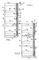
- FIG. 1-3 there is illustrated generally a typical three high lateral file cabinet in accordance with the present invention shown generally at 10.
- the cabinet includes a base 11 and a top 12.
- the cabinet also includes side walls 13, a back 14 and a front shown generally at 15.
- each drawer is provided with a flip-up door as seen at 23, 24 and 25, respectively.
- the flip-up door 24 is pivoted upwardly about its top pivot 27 and is then slid rearwardly into the cabinet to the recessed horizontal position 28 seen in Figures 2 and 3. Then the drawer 18 may be pulled out.
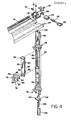
- the vertical track may be secured to the interior of the exterior side wall of the cabinet as indicated by the double sided adhesive tape 31 in Figure 10.
- the track is generally channel-shape and includes a back 32 and two legs 33 and 34 which extend from the back through the rebent offsets indicated at 35 and 36, respectively.
- the interior of each leg at the offset is provided with a laterally directed semi-circular channel as seen at 37 and 38 with the interior of the legs outwardly of such channel being tapered as indicated at 39 and 40, respectively.
- the semi-circular channels adjacent the offsets provide a vertical guide track for a plurality of vertically extending locking bars seen at 42, 43 and 44, there being one locking bar for each pull-out drawer.
- Such locking bars may be height coextensive with such drawers. If the drawers vary in height, so may the locking bars.
- each vertically extending locking bar is generally channel-shape and includes a web 50 and two edge flanges 51 and 52.
- the edge flanges extend throughout the major height of the locking bar except for two portions seen at 54 and 55 near the ends of the bar and through such portions the edge flanges merge into a single somewhat more shallow center rib seen at 56 and 57.
- the locking bar is provided with two relatively short legs seen at 60 and 61 which include semicircular lateral projections 62 and 63 adapted to fit within the semi-circular channels 37 and 38 of the track.
- the locking bar interiorly adjacent the legs 60 and 61 may be undercut as indicated at 64 and 65 in Figure 10. Such undercuts provide a degree of flexibility to the legs 60 and 61 so that the legs may be snapped into the track, camming over the ramps 39 and 40.
- each locking bar is provided at its lower end with a circular stud 68 and at its upper end with a projecting shelf 69, except for the top bar 42.
- the stud 68 at its outer end includes a downwardly projecting tab 70.
- the shelf 69 may be reinforced with a gusset 71.
- each locking bar extend across the top and bottom as seen at 73 and 74 and the upper end of the locking bar, again excepting the top bar, may be provided with a slightly projecting transverse tongue 75 which is adapted to fit within a similarly configured transverse groove in the bottom of the locking bar indicated at 76. In this manner the tongue and groove illustrated assist in maintaining the locking bars in vertical alignment within the track.
- Each stud 68 is adapted to receive a locking cam 78 shown in greater detail in Figure 12.
- Each locking cam includes a circular aperture 80 surrounded by a slightly elevated interior face 81 which is designed to bear against the slightly elevated exterior face 82 surrounding the stud 68 on the locking bar.
- the circular hole 80 includes an upwardly extending radial slot or keyway 83 which is adapted to clear the downwardly projecting tab 70 on the stud.
- the locking cam includes two alternate bearing surfaces seen at 84 and 85 which are 90° apart when measured from the center of the hole 80 or the stud 68.
- the radial difference between the bearing surfaces is the displacement of the cam. From the shorter displacement bearing surface 84 to the larger displacement surface 85 the cam includes an inclined ramp 86 and a fairly sharp yet radiused corner 87.
- the cam also includes a fairly long normally vertically extending projecting surface 90 which is adapted to engage a drawer pin as hereinafter described. Associated with the projecting surface 90 is a hook finger 91 which is substantially radially spaced from the surface 90 and which includes an interior or bight portion 92 which extends inwardly from the surface 90 at an obtuse angle.
- the locking cam 78 includes a second hook finger 94 which extends in curved fashion from the front of the upper end of the projection 95 which includes the projecting surface 90.
- each drawer 17, 18 and 19 is provided with a laterally projecting drawer pin seen at 96, 97 and 98 which, when the drawer is closed, is positioned immediately behind the vertically projecting surface 90 of each interlock cam.
- each flip-up door 23, 24 and 25 is provided with a laterally projecting interior pin seen at 99, 100 and 101 which is designed to be engaged by the hook finger 94.
- each door pin fits within the circular bight portion 102 of the hook finger 94.
- a compression spring 104 which may be situated in spring retainer 105 which bars against slider 106 provided with shelf 107.
- the shelf bears against the appropriate bearing surface of the interlock cam 78 of the lowermost locking bar 44 and urges all of the locking bars upwardly within the track 30.
- the shelf 107 may overlie and engage the base or other fixed stop in the cabinet when the locking bars are urged downwardly.
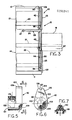
- the uppermost locking bar 42 instead of being provided with a shelf includes a top triangular projection 109 which bears against lock cam 110 mounted for rotation on the end of transverse lock shaft 111.
- the lock cam 110 is rotated 90° by the key 113 which fits within lock core 114 which in turn fits within barrel 115, both fitting in bracket 116 secured to the top transverse frame member 17.
- the bracket 116 includes a boss 119 accommodating the transverse shaft 111.
- the lock cam fits on the projecting end of the shaft opposite the viewer in Figure 4.
- the shaft may have a lock cam on its end toward the viewer engaging an interlock mechanism which is a mirror image of that illustrated in Figure 4. In this manner the drawers and doors are locked on both sides.
- the lock cam includes a hub 121 adapted to receive the end of shaft 111.
- the shaft may be provided with a flat as is the recess 122 in the hub and the shaft may be secured in place by a set screw or other suitable fastener extending through the tapped hole 123.
- the lock cam includes a radial arm 125 which includes a narrow tip 126 which in turn includes a socket or recess 127.
- the recess in the tip of the lock cam is designed to mate with the tip of the triangular portion 109 on the top locking bar 42.
- the lock cam on the side opposite the hub 121 includes bevel gearing indicated at 129 which extends slightly beyond 90° of the outside face of the lock cam. Such bevel gearing is in mesh with the bevel gearing 130 of lock pinion 131 which is driven for rotation by the core 114 and, of course, key 113.
- Lock cam 110 like the locking cams 78, has two bearing surfaces indicated at 133 and 134 which are 90° apart. The displacement of the lock cam is substantially the same as the displacement of the locking cams, which is such limited distance.
- the cabinet is illustrated in its locked condition.
- the rotation of key 113 has positioned the tip of the lock cam 110 at the top of the cabinet in the down position and this in turn has forced the combination of locking bars downwardly compressing the spring 104 at the bottom of the cabinet.
- the spring compressed the entire stack of lock bars and the associated cams are moved downwardly the predetermined limited distance through which the spring if deflected.
- Such downward movement causes the lock fingers 94 of each cam to engage the lock pins on the flip-up doors and thus the doors are unable to swing open or to the right as seen in Figure 1.
- the pull-out drawers are unable to be pulled out because the projecting surfaces 90 of each cam interfere with the drawer pins 96, 97 and 98. Since the cams are unable to rotate when the spring is deflected both the drawers and doors are locked.
- the hook finger 91 is now positioned to catch the drawer pin 97 and as the drawer is returned to its closed position, the cam oscillates back 90° permitting the spring to return to its undeflected condition thus enabling any other drawer to be pulled out.
- the other drawers cannot be pulled out until the displaced locking cam returns to its original position.
- the key may again be employed to rotate the lock cam to its down or locked position compressing the spring to lock the doors shut and the drawers in.
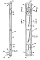
- the office cabinet 140 illustrated is in the form of a pedestal or credenza type filing unit.
- pedestal units are normally approximately work surface height and are often used in connection with work surfaces.
- the unit 140 includes a back 141 and a base 142.
- the top is indicated at 143 and the front is seen on the right in Figures 13, 14 and 15 as indicated at 144.
- the unit may include two drawers 146 and 147 which may vary in height and the unit also includes a top relatively shallow convenience tray 148 which functions much as a desk center drawer in which pencils and other office odds and ends are normally stored.
- the front of the cabinet may include a top molding 150 in the center of which is a lock for the cabinet.
- a vertical track near the front of the cabinet as indicated at 152.
- Such vertical track may extend the full height of the cabinet and as seen in Figure 16 at the bottom includes a fixed bar 153 which includes an inwardly projecting shelf 154 on the top thereof.
- the bar 153 fits within the track 152 in the same manner as the other bars hereinafter described which may be in the same manner as the bars previously described.
- a locking bar 156 Positioned above the bar 153 is a locking bar 156 which is provided with a locking cam 157 pivoted to the bottom interior thereof.
- the locking bar 156 is provided with a shelf on the upper end as seen at 158.
- a locking bar 159 Positioned above the locking bar 156 is a locking bar 159 which includes a locking cam 160 pivoted to the lower end thereof and a shelf projecting from the inner upper end as indicated at 161.
- the locking bars 156 and 159 as illustrated vary in height and such height corresponds to the difference in height of the drawers 147 and 146, respectively.
- a further locking bar 163 for the convenience tray which includes at the top thereof a shelf 164.
- the locking bar 163 is provided with an inwardly directed cross-shape pin or follower 165.
- the follower is rigidified by a triangular gusset 166.
- a compression spring 168 held in place by a fixed spring retainer 169.
- the locking bars in the pedestal unit embodiment may be of the same configuration and construction as those previously described in connection with the full height cabinet embodiment and such locking bars slide within the track 152 and are stacked on top of each other for limited distance movement within such track.
- the locking bars 159 and 156 include pivoted to the lower end thereof the locking cams 160 and 157, respectively, which are shown in greater detail in Figure 17.
- the locking cam 160 includes a bearing portion 170 and a radially displaced bearing portion 171 90° from the center 172 of the pivot.
- the cam surface between such bearing portions includes a ramp or slope 173 and a fairly sharp radiused corner 174.
- Projecting oppositely from the bearing surface 170 is a projection 175 which includes a projecting interference surface 176 which is adapted to engage drawer pin 178 seen in Figures 13-15.
- Drawer pin 179 for drawer 147 engages the interlock cam 157.
- Positioned adjacent the projecting surface 176 is the hook finger 180 with the bight portion of the hook extending at an obtuse angle with respect to the projecting surface 176. Since the cabinet has no flip-up doors, a second hook need not be provided.
- the interlock cams 160 and 157 cooperate with the drawer pins 178 and 179 in the same manner as in the full height cabinet embodiment.
- the inwardly projecting pin or projection 165 on the top locking bar 163 cooperates with a cam ramp seen at 184 in Figures 13-15 which is on the top of the convenience tray 148.
- cam ramp includes a notch 185 which includes a shoulder 186 on the front side and an inclined ramp 187 on the rear side.
- ramp 188 at the rear of the tray as illustrated to facilitate insertion of the tray.
- the cabinet may be locked by key 190 turning core 191 in barrel 192.
- the key when inserted, rotates element 193 90°, such element being journaled in half hubs 194 and 195 secured to the rear of molding 150.
- the element 193 includes a diametral arm 197 with holes at each end.
- the bent end 198 of rod link 199 projects through one of the holes, the opposite end of the rod link being bent as indicated at 200 to fit through hole 201 at the inner end of locking arm 202.
- the locking arm is pivoted for horizontal swinging movement on shaft 203 and includes an offset end 204. In the locked condition of the cabinet the arm offset end 204 is inserted between shelf 164 of the top locking bar 163 and the bottom of spring retainer 169. This prevents the locking bars below from moving upwardly and the spring from being compressed. When the cabinet is unlocked, the offset end 204 is clear of the shelf 164.
- interlock mechanism is illustrated on one side of the cabinet only, it will be appreciated that a mirror image of the interlock mechanism may be provided on the opposite side, both being locked from the central key lock in the top molding 150.
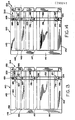
- FIG. 13 the pedestal cabinet is shown locked.
- the rotation of the key 190 has pivoted the locking arm 202 into the space between the interlock spring retainer 169 and the top of the interlocking bar 163.
- Such blocking of movement also prevents the interlock cams 160 and 157 from rotating.
- both drawers 146 and 147 are locked because the interlocking cams are not able to rotate.
- the top tray is locked in position because the pin 165 projecting from the top locking bar cannot move up.
- the drawer 146 has been pulled out and the drawer pin 178 has engaged and rotated the interlock cam 160 90°.
- the displacement of the cam 160 has taken up the limited movement available to the locking bars. This has forced the combination of locking bars above the rolled out drawer upwardly compressing the spring 168. Because the spring deflection is limited to the displacement of one interlock cam, or the tray ramp displacement, the remaining drawer is prevented from extending.
- the top convenience tray may nonetheless be pulled out or pushed back without affecting the interlock system. When the tray is pulled out alone, the spring is compressed by elevating the top bar. This permits one of the two drawers below to be pulled out, but not both.
- Essentially all of the parts may be fabricated from rigid plastic materials having a low coefficient of friction so that the parts will work smoothly and quietly.
Landscapes
- Drawers Of Furniture (AREA)
- Sheet Holders (AREA)
Applications Claiming Priority (2)
| Application Number | Priority Date | Filing Date | Title |
|---|---|---|---|
| US07/047,269 US4768844A (en) | 1987-05-08 | 1987-05-08 | Office cabinet |
| US47269 | 1987-05-08 |
Publications (1)
| Publication Number | Publication Date |
|---|---|
| EP0290241A1 true EP0290241A1 (en) | 1988-11-09 |
Family
ID=21948004
Family Applications (1)
| Application Number | Title | Priority Date | Filing Date |
|---|---|---|---|
| EP88304035A Withdrawn EP0290241A1 (en) | 1987-05-08 | 1988-05-04 | Office cabinet |
Country Status (4)
| Country | Link |
|---|---|
| US (1) | US4768844A (enExample) |
| EP (1) | EP0290241A1 (enExample) |
| JP (1) | JPS6425806A (enExample) |
| KR (1) | KR880013504A (enExample) |
Cited By (10)
| Publication number | Priority date | Publication date | Assignee | Title |
|---|---|---|---|---|
| FR2700803A1 (fr) * | 1993-01-26 | 1994-07-29 | Schlumberger Ind Sa | Dispositif pour commander l'ouverture/fermeture d'une pluralité de portes donnant accès chacune à une enceinte. |
| EP0669439A1 (en) * | 1994-02-25 | 1995-08-30 | Flexiform Business Furniture Limited | Cabinet locking device |
| FR2728148A1 (fr) * | 1994-12-20 | 1996-06-21 | Huwil Werke Gmbh | Mecanisme de verrouillage d'extraction pour tiroirs superposes |
| GB2318042A (en) * | 1996-10-12 | 1998-04-15 | Andrew Clive Jackson | Drawer interlock for a cabinet |
| FR2776902A1 (fr) * | 1998-04-03 | 1999-10-08 | Ojmar Sa | Dispositif de blocage de tiroirs de meuble |
| WO1999053808A3 (en) * | 1998-04-20 | 1999-12-29 | Mars Inc | Apparatus for dispensing of bulk product |
| EP1059408A3 (fr) * | 1999-06-10 | 2002-03-06 | Ojmar S.A. | Système de blocage pour tiroirs dans des meubles |
| EP1154107A3 (de) * | 2000-05-08 | 2003-05-14 | HUWIL-Werke GmbH Möbelschloss- u. Beschlagfabriken | Ausziehsperre für übereinander angeordnete Schubladen und Möbel mit einer solchen Ausziehsperre |
| NL1014248C2 (nl) * | 1999-02-02 | 2005-02-15 | Thomas Regout Usa Inc | Railsamenstel met naar de beginstand geleidende inrichting en koppelinrichting. |
| NL1029528C2 (nl) * | 2005-07-14 | 2007-01-17 | Thomas Regout Internat B V | Anti-kantelinrichting voor boven elkaar gelegen, uitschuifbare eenheden, alsmede een daarmee uitgerust meubelstuk. |
Families Citing this family (48)
| Publication number | Priority date | Publication date | Assignee | Title |
|---|---|---|---|---|
| US5050942A (en) * | 1987-08-11 | 1991-09-24 | Supreme Equipment And Systems Corp. | File interlock system |
| CA1307022C (en) * | 1988-07-26 | 1992-09-01 | Isy S. Pratzer | Anti-tip mechanism and method for providing anti-tip device |
| US4957334A (en) * | 1988-11-01 | 1990-09-18 | Priority Mfg. Corp. | Interlock system |
| US4960309A (en) * | 1988-11-29 | 1990-10-02 | Steelcase Inc. | Drawer lock and interlock mechanism |
| US5056876A (en) * | 1988-11-29 | 1991-10-15 | Steelcase Inc. | Drawer lock and interlock mechanism |
| US4993784A (en) * | 1988-12-07 | 1991-02-19 | Engineered Security Products Corporation | Locking device |
| US4889396A (en) * | 1988-12-12 | 1989-12-26 | G. A. Richards Company | Drawer interlock |
| US4966423A (en) * | 1989-12-21 | 1990-10-30 | Russ Bassett Company | Cabinet drawer interlocking apparatus |
| US5056877A (en) * | 1990-05-08 | 1991-10-15 | Pundra Industries Limited | Locking anti-tip device |
| US5184887A (en) * | 1990-10-26 | 1993-02-09 | Herman Miller, Inc. | Drawer interlock system |
| US5199774A (en) * | 1990-11-27 | 1993-04-06 | Kimball International, Inc. | Combination lock and interlock for a file cabinet |
| JPH06121717A (ja) * | 1991-05-10 | 1994-05-06 | Ibiken Kk | 引出式多段キャビネットの転倒防止装置 |
| FR2677071B1 (fr) * | 1991-06-03 | 1995-09-08 | Ronis Sa | Mecanisme de verrouillage-deverrouillage pour meuble a tiroirs et meuble a tiroirs equipe d'un tel mecanisme. |
| US5303994A (en) * | 1992-06-05 | 1994-04-19 | Steelcase Inc. | Drawer interlock |
| FR2699057B1 (fr) * | 1992-12-11 | 1995-01-13 | Ronis Sa | Dispositif réglable de condamnation des tiroirs d'un meuble et meuble équipé d'un tel dispositif. |
| US5335986A (en) * | 1993-01-08 | 1994-08-09 | Metalworks, Inc. | Interlock assembly |
| US5567027A (en) * | 1993-06-11 | 1996-10-22 | Herman Miller, Inc. | Cabinet drawer lock |
| US5427445A (en) * | 1994-10-05 | 1995-06-27 | Quest Engineering | Drawer interlock structure |
| GB9421035D0 (en) * | 1994-10-19 | 1994-12-07 | Brown F C Steel Equipment | Interlock mechanism |
| GB9502513D0 (en) * | 1995-02-09 | 1995-03-29 | Jackson Paul A | Improvements relating to filing cabinets |
| EP0738813A1 (de) * | 1995-03-24 | 1996-10-23 | Merz-Meyer Ag | Möbelstück |
| DE69630304T2 (de) * | 1995-04-21 | 2004-08-05 | Metro Industries, Inc., Reno | Sicherheitssystem und verschließbarer modularer Lager- und Stützaufbau |
| US6296332B1 (en) | 1996-07-12 | 2001-10-02 | Accuride International, Inc. | File interlock system and mechanism |
| DE69715980T2 (de) * | 1996-07-12 | 2003-01-30 | Accuride International, Inc. | Verriegelungssystem mit Stangenverschluss für Schubladen |
| US5853237A (en) * | 1997-01-31 | 1998-12-29 | Haworth, Inc. | Base for lateral file |
| US6170927B1 (en) | 1998-11-20 | 2001-01-09 | Steelcase Development Inc. | Drawer interlink system |
| US6969129B2 (en) * | 2002-08-21 | 2005-11-29 | Compx International, Inc. | Anti-tip interlocking linkage mechanism for vertical cabinets |
| US7520576B2 (en) * | 2002-08-21 | 2009-04-21 | Compx International Inc. | Anti-tip interlocking linkage mechanism for vertical cabinets |
| US7469979B2 (en) * | 2004-03-19 | 2008-12-30 | Steelcase Inc. | Pedestal system |
| US20060138915A1 (en) * | 2004-12-28 | 2006-06-29 | Goldberg Mark A | Mobile computer security cabinet |
| US7481503B2 (en) | 2006-01-19 | 2009-01-27 | Steelcase Inc. | Storage cabinet assembly |
| ES2298022B1 (es) * | 2006-03-03 | 2009-07-21 | Ojmar, S.A. | Sistema de bloqueo, para archivadores modulares apilables. |
| TWI297596B (en) * | 2006-09-21 | 2008-06-11 | Sun Chain Metal Industry Co Ltd | Interlocking device for a drawer guideway |
| US20080116327A1 (en) * | 2006-11-22 | 2008-05-22 | Goldberg Mark A | Mobile workstation |
| US20080142660A1 (en) * | 2006-12-18 | 2008-06-19 | Goldberg Mark A | Wall mounted workstation |
| US7798580B2 (en) * | 2007-01-04 | 2010-09-21 | Global Equipment Company Inc. | Mobile computer security cart |
| ES2304106B1 (es) * | 2007-02-23 | 2009-05-01 | Ojmar S.A. | Sistema de bloqueo para cajones de muebles. |
| US7901017B1 (en) * | 2007-07-02 | 2011-03-08 | Corry Contract, Inc. | Security file cabinet with self-closing, self-locking drawers |
| US8434836B2 (en) * | 2007-08-30 | 2013-05-07 | Waterloo Industries, Inc. | Slide assembly |
| US8870308B2 (en) * | 2008-11-17 | 2014-10-28 | Versatility Tool Works & Manufacturing Company | Universal safety lock system for tool cabinets |
| US8651591B1 (en) * | 2012-12-31 | 2014-02-18 | E-Make Co., Ltd. | Lock device for two way travel drawer |
| CN104005608A (zh) * | 2013-02-22 | 2014-08-27 | 上海迪米新型复合材料有限公司 | 多抽屉活动柜的互锁结构 |
| US8770680B1 (en) * | 2013-03-14 | 2014-07-08 | E-Make Co., Ltd. | Lock device for two-way travel drawer |
| US9187932B1 (en) * | 2014-07-12 | 2015-11-17 | E-Make Co., Ltd. | Lock device with positioning assembly for two-way travel drawer |
| DE202018104659U1 (de) * | 2018-08-14 | 2019-11-15 | Martin Lehmann Gmbh & Co. Kg | Auszugssperre und Anordnung einer Auszugssperre in einem Möbel |
| SE544594C2 (en) * | 2020-12-14 | 2022-09-20 | Ikea Supply Ag | Arrangement for tipping over prevention of a chest of drawers and chest of drawers comprosing such arrangement |
| SE547185C2 (en) * | 2021-02-12 | 2025-05-20 | Inter Ikea Sys Bv | Locking arrangement for drawers in a cabinet, a cabinet comprising such arrangement and a drawer rail |
| DE102021119647A1 (de) * | 2021-07-28 | 2023-02-02 | Martin Lehmann GmbH & Co. Kommanditgesellschaft | Führungsprofil für eine Auszugssperre, Auszugssperre, Möbel und Verfahren zur Bestückung eines Führungsprofils |
Citations (3)
| Publication number | Priority date | Publication date | Assignee | Title |
|---|---|---|---|---|
| US3888558A (en) * | 1974-02-19 | 1975-06-10 | Sunar Ltd | Lock and interlock mechanism |
| US3900236A (en) * | 1974-06-28 | 1975-08-19 | Gf Business Equip | File interlock |
| CA1175875A (en) * | 1983-02-25 | 1984-10-09 | Office Specialty Division Of Hollanding Inc. | Anti-tip blocking device |
Family Cites Families (11)
| Publication number | Priority date | Publication date | Assignee | Title |
|---|---|---|---|---|
| US896028A (en) * | 1908-03-12 | 1908-08-11 | Harry M Leese | Desk. |
| US2240067A (en) * | 1937-07-06 | 1941-04-29 | All Steel Equip Company Inc | File cabinet and the like |
| US2853355A (en) * | 1955-07-22 | 1958-09-23 | Diebold Inc | Insulated cabinet construction |
| US3941441A (en) * | 1974-01-02 | 1976-03-02 | Steelcase Inc. | Drawer interlock system |
| US3870387A (en) * | 1974-03-27 | 1975-03-11 | Harbor Universal Inc | File drawer interlock mechanism |
| US3909090A (en) * | 1974-11-18 | 1975-09-30 | Gf Business Equip | Office appliance |
| US4303287A (en) * | 1980-02-04 | 1981-12-01 | Vickers Limited | Locking mechanism for a storage cabinet |
| US4298236A (en) * | 1980-07-14 | 1981-11-03 | Artopex Inc. | Safety lock system for vertically stacked storage elements |
| US4355851A (en) * | 1980-11-28 | 1982-10-26 | Herman Miller, Inc. | Drawer interlock system |
| US4425013A (en) * | 1981-05-26 | 1984-01-10 | Pacific Furniture Manufacturing Co. | Apparatus for locking cabinet drawers |
| CA1182507A (en) * | 1981-12-24 | 1985-02-12 | Nightingale Saro Incorporated | Interlock for drawers |
-
1987
- 1987-05-08 US US07/047,269 patent/US4768844A/en not_active Expired - Fee Related
-
1988
- 1988-05-04 EP EP88304035A patent/EP0290241A1/en not_active Withdrawn
- 1988-05-07 JP JP63109923A patent/JPS6425806A/ja active Granted
- 1988-05-07 KR KR1019880005302A patent/KR880013504A/ko not_active Withdrawn
Patent Citations (3)
| Publication number | Priority date | Publication date | Assignee | Title |
|---|---|---|---|---|
| US3888558A (en) * | 1974-02-19 | 1975-06-10 | Sunar Ltd | Lock and interlock mechanism |
| US3900236A (en) * | 1974-06-28 | 1975-08-19 | Gf Business Equip | File interlock |
| CA1175875A (en) * | 1983-02-25 | 1984-10-09 | Office Specialty Division Of Hollanding Inc. | Anti-tip blocking device |
Cited By (15)
| Publication number | Priority date | Publication date | Assignee | Title |
|---|---|---|---|---|
| FR2700803A1 (fr) * | 1993-01-26 | 1994-07-29 | Schlumberger Ind Sa | Dispositif pour commander l'ouverture/fermeture d'une pluralité de portes donnant accès chacune à une enceinte. |
| EP0608585A1 (fr) * | 1993-01-26 | 1994-08-03 | Schlumberger Industries | Dispositif pour commander l'ouverture/fermeture d'une pluralité de portes donnant accès chacune à une enceinte |
| EP0669439A1 (en) * | 1994-02-25 | 1995-08-30 | Flexiform Business Furniture Limited | Cabinet locking device |
| FR2728148A1 (fr) * | 1994-12-20 | 1996-06-21 | Huwil Werke Gmbh | Mecanisme de verrouillage d'extraction pour tiroirs superposes |
| US5702167A (en) * | 1994-12-20 | 1997-12-30 | Huwil-Werke Gmbh | Drawer locking means for drawers arranged one above the other |
| GB2318042A (en) * | 1996-10-12 | 1998-04-15 | Andrew Clive Jackson | Drawer interlock for a cabinet |
| FR2776902A1 (fr) * | 1998-04-03 | 1999-10-08 | Ojmar Sa | Dispositif de blocage de tiroirs de meuble |
| WO1999053808A3 (en) * | 1998-04-20 | 1999-12-29 | Mars Inc | Apparatus for dispensing of bulk product |
| GB2352238A (en) * | 1998-04-20 | 2001-01-24 | Mars Inc | Apparatus for dispensing of bulk product |
| GB2352238B (en) * | 1998-04-20 | 2002-11-20 | Mars Inc | Apparatus for dispensing of bulk product |
| NL1014248C2 (nl) * | 1999-02-02 | 2005-02-15 | Thomas Regout Usa Inc | Railsamenstel met naar de beginstand geleidende inrichting en koppelinrichting. |
| EP1059408A3 (fr) * | 1999-06-10 | 2002-03-06 | Ojmar S.A. | Système de blocage pour tiroirs dans des meubles |
| ES2188297A1 (es) * | 1999-06-10 | 2003-06-16 | Ojmar Sa | Sistema de bloqueo para cajones de muebles. |
| EP1154107A3 (de) * | 2000-05-08 | 2003-05-14 | HUWIL-Werke GmbH Möbelschloss- u. Beschlagfabriken | Ausziehsperre für übereinander angeordnete Schubladen und Möbel mit einer solchen Ausziehsperre |
| NL1029528C2 (nl) * | 2005-07-14 | 2007-01-17 | Thomas Regout Internat B V | Anti-kantelinrichting voor boven elkaar gelegen, uitschuifbare eenheden, alsmede een daarmee uitgerust meubelstuk. |
Also Published As
| Publication number | Publication date |
|---|---|
| KR880013504A (ko) | 1988-12-21 |
| JPS6425806A (en) | 1989-01-27 |
| JPH0418844B2 (enExample) | 1992-03-27 |
| US4768844A (en) | 1988-09-06 |
Similar Documents
| Publication | Publication Date | Title |
|---|---|---|
| EP0290241A1 (en) | Office cabinet | |
| US5056877A (en) | Locking anti-tip device | |
| US5634701A (en) | Multi-drawer cabinet having a drawer lock-out mechanism | |
| US5303994A (en) | Drawer interlock | |
| US5257860A (en) | Drawer lock mechanism including push button latch | |
| US5997114A (en) | Drawer interlock to non-interlock conversion device | |
| US4711505A (en) | Locking system | |
| CA1061849A (en) | Lock and interlock mechanism | |
| CA2210280C (en) | Rod-based file interlock system | |
| US7520576B2 (en) | Anti-tip interlocking linkage mechanism for vertical cabinets | |
| US4246769A (en) | Cam for cabinet locking system | |
| US5599078A (en) | Anti-tip device for file cabinets | |
| CA2044025C (en) | Anti-tilt and locking mechanism for multi-drawer cabinets | |
| US5314244A (en) | Pharmaceutical cabinet locking arrangement | |
| JPH0777909B2 (ja) | 磁気テープカセット用の収容容器 | |
| US4838624A (en) | Furniture anti-tip and lock mechanism | |
| US5050942A (en) | File interlock system | |
| US5567027A (en) | Cabinet drawer lock | |
| US3936108A (en) | File cabinet drawer locking mechanism | |
| US4960309A (en) | Drawer lock and interlock mechanism | |
| US4721347A (en) | Cabinet drawer locking system | |
| GB1587567A (en) | Locking mechanism | |
| US6173593B1 (en) | Concealed locking mechanism and method for use with drawers or cabinet doors or the like | |
| US6890043B2 (en) | Lock cam with resilient arm for a cabinet lock | |
| JP2018048544A (ja) | フラップ扉 |
Legal Events
| Date | Code | Title | Description |
|---|---|---|---|
| PUAI | Public reference made under article 153(3) epc to a published international application that has entered the european phase |
Free format text: ORIGINAL CODE: 0009012 |
|
| AK | Designated contracting states |
Kind code of ref document: A1 Designated state(s): AT BE CH DE FR GB IT LI LU NL SE |
|
| 17P | Request for examination filed |
Effective date: 19890424 |
|
| 17Q | First examination report despatched |
Effective date: 19900216 |
|
| STAA | Information on the status of an ep patent application or granted ep patent |
Free format text: STATUS: THE APPLICATION IS DEEMED TO BE WITHDRAWN |
|
| 18D | Application deemed to be withdrawn |
Effective date: 19900627 |