EP0288668A2 - Leuchtengehäuse - Google Patents
Leuchtengehäuse Download PDFInfo
- Publication number
- EP0288668A2 EP0288668A2 EP88101837A EP88101837A EP0288668A2 EP 0288668 A2 EP0288668 A2 EP 0288668A2 EP 88101837 A EP88101837 A EP 88101837A EP 88101837 A EP88101837 A EP 88101837A EP 0288668 A2 EP0288668 A2 EP 0288668A2
- Authority
- EP
- European Patent Office
- Prior art keywords
- luminaire
- trough
- lamp
- light fixture
- light
- Prior art date
- Legal status (The legal status is an assumption and is not a legal conclusion. Google has not performed a legal analysis and makes no representation as to the accuracy of the status listed.)
- Ceased
Links
Images
Classifications
-
- F—MECHANICAL ENGINEERING; LIGHTING; HEATING; WEAPONS; BLASTING
- F21—LIGHTING
- F21V—FUNCTIONAL FEATURES OR DETAILS OF LIGHTING DEVICES OR SYSTEMS THEREOF; STRUCTURAL COMBINATIONS OF LIGHTING DEVICES WITH OTHER ARTICLES, NOT OTHERWISE PROVIDED FOR
- F21V3/00—Globes; Bowls; Cover glasses
- F21V3/04—Globes; Bowls; Cover glasses characterised by materials, surface treatments or coatings
-
- F—MECHANICAL ENGINEERING; LIGHTING; HEATING; WEAPONS; BLASTING
- F21—LIGHTING
- F21S—NON-PORTABLE LIGHTING DEVICES; SYSTEMS THEREOF; VEHICLE LIGHTING DEVICES SPECIALLY ADAPTED FOR VEHICLE EXTERIORS
- F21S8/00—Lighting devices intended for fixed installation
- F21S8/04—Lighting devices intended for fixed installation intended only for mounting on a ceiling or the like overhead structures
-
- F—MECHANICAL ENGINEERING; LIGHTING; HEATING; WEAPONS; BLASTING
- F21—LIGHTING
- F21V—FUNCTIONAL FEATURES OR DETAILS OF LIGHTING DEVICES OR SYSTEMS THEREOF; STRUCTURAL COMBINATIONS OF LIGHTING DEVICES WITH OTHER ARTICLES, NOT OTHERWISE PROVIDED FOR
- F21V15/00—Protecting lighting devices from damage
- F21V15/01—Housings, e.g. material or assembling of housing parts
Definitions
- the invention relates to a luminaire housing according to the preamble of claim 1.
- luminaire housings which have an opaque upper part which contains the fastening devices, lamp holders, electrical supply devices and connectors and which is closed at the bottom by a translucent luminaire trough.
- the lamp tray which is mostly made of plastic, can be transparent, opal (milky) or equipped with a light-scattering prism structure. It is known to provide the outer surface of the upper part of the lamp with a granular, rough structure in order to prevent any unevenness or irregularities in this outer surface from appearing strongly.
- the luminaire trays of the well-known luminaire housings stand out visually from the luminaire upper part. If the luminaire trays have a smooth outer surface, they have a certain mirror effect. If extraneous light falls on the luminaire pan when the lamp is switched off, this is reflected. There are bumps and irregularities, e.g. Wave formation, clearly recognizable, even if these irregularities are very weak. As is well known, bumps or wave formations are very clearly visible in the reflected light. In the case of a smooth, reflecting trough, when the lamp is switched off, all bumps can be recognized by reflection, e.g. also such unevenness caused by sagging. If the luminaire tray has a prism structure, the light effect of the prisms means that no uniform light scatter and light distribution can be achieved.
- the invention has for its object to provide a lamp housing of the type specified in the preamble of claim 1, which has a pleasing uniform appearance and which is designed so that there is a uniform light scattering while avoiding mirror effects.
- the luminaire upper part and luminaire trough are provided with a grainy structured outer surface.
- the luminaire housing has one unit neat appearance with a matt outer surface. The luminaire housing appears to be "from a single source", as the granular structure of the luminaire top continues in the tub.
- a particular advantage is that the granular structure of the outside of the luminaire trough prevents reflections because the light is diffusely reflected in Lambertian scattering. In this way, reflection effects are avoided, so that any deformation of the luminaire tray is not recognizable even under the influence of extraneous light.
- the luminaire trough appears equally bright from all directions due to the light-scattering outer surface. There is therefore no glare and largely ideal Lambertian light scattering.
- Claims 2 and 3 relate to preferred ranges of the average roughness.
- the luminaire housing forms uniform appearing areas at the points where the luminaire upper part and luminaire trough meet.
- the transition between the upper part and the bath is hardly recognizable.
- the lamp housing in the joint area of the upper part and the tub has a kink line that blurs any inaccuracies in the color matching.
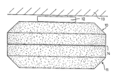
- the drawing shows an end view of the lamp.
- the ceiling lamp shown has a lamp upper part 10 made of metal or plastic and a lamp trough 11 closing the upper part 10 downwards.
- the lamp top 10 is closed at the top and on the sides and has the shape of an inverted trough.
- the luminaire trough 11 is inserted into the lower opening of the upper luminaire part 10 in such a way that the outer walls of the upper part 10 and trough 11 abut one another flush in the transition region 14.
- the lamp trough 11 continues the lower vertical region of the outer wall of the upper part 10 downwards.
- the outer surface of the upper part 10 of the lamp is structured in a granular manner in a known manner.
- This structure can be produced in that a metallic upper part of the lamp is coated with a structural lacquer or that an upper part made of plastic is made in a blow or injection mold, the walls of which are sandblasted, eroded, etched or the like. have a granular structure.
- the lamp tray 11 which is made of a translucent plastic, is produced by injection molding or by blowing.
- the mold used for this is treated by sandblasting, erosion processes or by etching, so that the mold wall that forms the outer surface of the luminaire trough is given a fine-grained structure.
- the outer surfaces of the upper part of the lamp 10 and the luminaire trough are thus irregularly fine-grained, the roughness depth and roughness distribution being approximately the same for the two parts mentioned.
- the inner surface of the lamp trough 11 can also be structured accordingly.
- the luminaire tray is made of a material that has constant thickness over the entire surface area and in which the material thickness is much greater than the roughness depth of the surface structure.
- the roughness depth of the luminaire tray is between 10 ⁇ m and 80 ⁇ m, and preferably between 16 ⁇ m and 40 ⁇ m.
Landscapes
- Engineering & Computer Science (AREA)
- General Engineering & Computer Science (AREA)
- Non-Portable Lighting Devices Or Systems Thereof (AREA)
Abstract
Description
- Die Erfindung betrifft ein Leuchtengehäuse nach dem Oberbegriff des Anspruchs 1.
- Für Leuchten, insbesondere Deckenleuchten, sind Leuchtengehäuse bekannt, die ein lichtundurchlässiges Oberteil aufweisen, welches die Befestigungseinrichtungen, Lampenfassungen, elektrischen Versorgungseinrichtungen und Verbinder enthält und das nach unten durch eine lichtdurchlässige Leuchtenwanne abgeschlossen ist. Die zumeist aus Kunststoff bestehende Leuchtenwanne kann durchsichtig, opal (milchig eingetrübt) oder mit einer lichtstreuenden Prismenstruktur ausgestattet sein. Es ist bekannt, die Außenfläche des Leuchtenoberteils mit einer körnigen, rauhen Struktur zu versehen, um zu vermeiden, daß etwaige Unebenheiten oder Ungleichmäßigkeiten dieser Außenfläche optisch stark in Erscheinung treten.
- Die Leuchtenwannen der bekannten Leuchtengehäuse setzen sich optisch stark von dem Leuchtenoberteil ab. Sofern die Leuchtenwannen eine glatte Außenfläche haben, haben sie eine gewisse Spiegelwirkung. Wenn bei ausgeschalteter Lampe Fremdlicht auf die Leuchtenwanne fällt, wird dieses reflektiert. Dabei sind Unebenheiten und Unregelmäßigkeiten, z.B. Wellenbildungen, genau erkennbar, selbst wenn diese Unregelmäßigkeiten nur sehr schwach ausgebildet sind. Bekanntlich sind Unebenheiten oder Wellenbildungen im reflektierten Licht sehr deutlich sichtbar. Man erkennt bei glatter spiegelnder Wanne bei ausgeschalteter Lampe also alle Unebenheiten durch Spiegelung, z.B. auch solche Unebenheiten, die durch Durchhängen bedingt sind. Hat die Leuchtenwanne eine Prismenstruktur, so kann infolge der Lichtwirkung der Prismen keine gleichmäßige Lichtstreuung und Lichtverteilung erreicht werden.
- Der Erfindung liegt die Aufgabe zugrunde, ein Leuchtengehäuse der im Oberbegriff des Anspruchs 1 angegebenen Art zu schaffen, das ein gefälliges einheitliches Aussehen hat und das so ausgebildet ist, daß sich eine gleichmäßige Lichtstreuung unter Vermeidung von Spiegeleffekten ergibt.
- Die Lösung dieser Aufgabe erfolgt erfindungsgemäß mit den im kennzeichnenden Teil des Anspruchs 1 angegebenen Merkmalen.
- Bei dem erfindungsgemäßen Leuchtengehäuse sind Leuchtenoberteil und Leuchtenwanne gleichermaßen mit einer körnig strukturierten Außenfläche versehen. Mit Ausnahme von Farb- oder Tönungsunterschieden zwischen Oberteil und Wanne hat das Leuchtengehäuse ein einheit liches Aussehen mit matter Außenfläche. Das Leuchtengehäuse erscheint gewissermaßen "wie aus einem Guß", da die körnige Struktur des Leuchtenoberteils sich in der Wanne fortsetzt.
- Ein besonderer Vorteil besteht darin, daß durch die körnige Struktur der Außenseite der Leuchtenwanne Reflektionserscheinungen vermieden werden, weil das Licht in Lambert'scher Streuung diffus reflektiert wird. Auf diese Weise werden Spiegelungseffekte vermieden, so daß etwaige Verformungen der Leuchtenwanne auch unter Fremdlichteinfluß nicht erkennbar sind.
- Wenn die im Innern des Leuchtengehäuses befindliche Lampe eingeschaltet ist, erscheint die Leuchtenwanne infolge der lichtstreuenden Außenfläche aus allen Richtungen gleich hell. Es entsteht also keine Blendwirkung und eine weitgehend ideale Lambert'sche Lichtstreuung.
- Vorteilhafte Ausgestaltungen und Weiterbildungen der Erfindung sind in den Unteransprüchen angegeben. Die Ansprüche 2 und 3 beziehen sich auf bevorzugte Bereiche der gemittelten Rauhtiefe. Mit den Merkmalen des Anspruchs 4 wird erreicht, daß das Leuchtengehäuse an den Stellen, an denen Leuchtenoberteil und Leuchtenwanne gegeneinanderstoßen, einheitlich erscheinende Flächen bildet. Bei entsprechender Farbabstimmung des Leuchtenoberteils zur Wanne, z.B. bei milchig weißem Oberteil, ist der Übergang zwischen Oberteil und Wanne kaum erkennbar. Nach Anspruch 5 hat das Leuchtengehäuse im Stoßbereich von Oberteil und Wanne eine Knicklinie, die etwaige Ungenauigkeiten der Farbtonabstimmung verwischt.
- Im folgenden wird unter Bezugnahme auf die einzige Figur der Zeichnung ein Ausführungsbeispiel der Erfindung näher erläutert.
- Die Zeichnung zeigt eine Stirnansicht der Leuchte.
- Die dargestellte Deckenleuchte weist ein Leuchtenoberteil 10 aus Metall oder Kunststoff sowie eine das Oberteil 10 nach unten abschließende Leuchtenwanne 11 auf. Das Leuchtenoberteil 10, das mit einer Haltevorrichtung 12 an der Decke 13 hängend befestigt ist, enthält eine oder mehrere langgestreckte Leuchtstofflampen sowie die Versorgungseinrichtungen (Vorschaltgeräte) für die Lampen. Das Leuchtenoberteil 10 ist nach oben und an den Seiten geschlossen und hat die Form einer umgekehrten Wanne. In die untere Öffnung des Leuchtenoberteils 10 ist die Leuchtenwanne 11 eingesetzt, und zwar so, daß die Außenwände von Oberteil 10 und Wanne 11 im Übergangsbereich 14 bündig gegeneinanderstoßen. Die Leuchtenwanne 11 setzt den unteren vertikalen Bereich der Außenwand des Oberteils 10 nach unten hin fort.
- Die Außenfläche des Leuchtenoberteils 10 ist in bekannter Weise körnig strukturiert. Diese Struktur kann dadurch erzeugt sein, daß ein metallisches Leuchtenoberteil mit einem Strukturlack beschichtet ist oder daß ein aus Kunststoff bestehendes Leuchtenoberteil in einer Blas- oder Spritzgußform hergestellt ist, deren Wände durch Sandstrahlen, Erodieren, Ätzen o.dgl. eine körnige Struktur erhalten haben.
- Die aus einem lichtdurchlässigen Kunststoff bestehende Leuchtenwanne 11 wird im Spritzgußverfahren oder im Blasverfahren hergestellt. Die dazu benutzte Form ist durch Sandstrahlen, Erosionsverfahren oder durch Ätzen behandelt, so daß diejenige Formwand, die die Außenfläche der Leuchtenwanne formt, eine feinkörnige Struktur erhält.
- Die Außenflächen von Leuchtenoberteil 10 und Leuchtenwanne sind somit unregelmäßig feinkörnig strukturiert, wobei die Rauhtiefe und Rauhheitsverteilung für die beiden genannten Teile etwa gleich sind. Zur Erhöhung der lichtstreuenden Wirkung kann auch die Innenfläche der Leuchtenwanne 11 entsprechend strukturiert sein. In jedem Fall besteht die Leuchtenwanne aus einem Material, das im gesamten Flächenbereich konstante Stärke hat und bei dem die Materialstärke viel größer ist als die Rauhtiefe der Oberflächenstruktur. Die Rauhtiefe der Leuchtenwanne beträgt zwischen 10µm und 80µm, und vorzugsweise zwischen 16µm und 40µm.
Claims (6)
dadurch gekennzeichnet,
daß die Leuchtenwanne (11) an ihrer Außenfläche ebenfalls eine körnige Struktur aufweist, deren Rauhtiefe und Rauhheitsverteilung im wesentlichen derjenigen des Leuchtenoberteils (10) entspricht.
Applications Claiming Priority (2)
| Application Number | Priority Date | Filing Date | Title |
|---|---|---|---|
| DE8706137U | 1987-04-29 | ||
| DE8706137U DE8706137U1 (de) | 1987-04-29 | 1987-04-29 | Leuchtengehäuse |
Publications (2)
| Publication Number | Publication Date |
|---|---|
| EP0288668A2 true EP0288668A2 (de) | 1988-11-02 |
| EP0288668A3 EP0288668A3 (de) | 1989-11-08 |
Family
ID=6807492
Family Applications (1)
| Application Number | Title | Priority Date | Filing Date |
|---|---|---|---|
| EP88101837A Ceased EP0288668A3 (de) | 1987-04-29 | 1988-02-09 | Leuchtengehäuse |
Country Status (2)
| Country | Link |
|---|---|
| EP (1) | EP0288668A3 (de) |
| DE (1) | DE8706137U1 (de) |
Cited By (1)
| Publication number | Priority date | Publication date | Assignee | Title |
|---|---|---|---|---|
| WO2005050087A1 (de) | 2003-11-21 | 2005-06-02 | Zumtobel Staff Gmbh | Leuchte mit transparentem lichtaustrittselement |
Families Citing this family (2)
| Publication number | Priority date | Publication date | Assignee | Title |
|---|---|---|---|---|
| DE4413644A1 (de) * | 1994-04-20 | 1995-10-26 | Cristallux Werk Waldachtal Gmb | Lichtabdeckung und Verfahren zu ihrer Herstellung |
| DE19621986B4 (de) * | 1996-04-04 | 2012-07-19 | Bts Gmbh & Co. Kg | Einschlagdübel |
Family Cites Families (4)
| Publication number | Priority date | Publication date | Assignee | Title |
|---|---|---|---|---|
| FR583356A (fr) * | 1923-10-01 | 1925-01-12 | Procédé de décoration cristallisée transparente ou translucide pour ampoules électriques, verreries d'éclairage ou autre, verroterie, etc. | |
| US3524051A (en) * | 1968-08-19 | 1970-08-11 | Gen Electric | Luminaire |
| GB1359325A (en) * | 1972-05-24 | 1974-07-10 | Merchant Adventurers Ltd | Lighting units |
| IT209727Z2 (it) * | 1985-12-20 | 1988-10-24 | Acrilux Srl | Struttura per un corpo illuminante, particolarmente del tipo a plafoniera. |
-
1987
- 1987-04-29 DE DE8706137U patent/DE8706137U1/de not_active Expired
-
1988
- 1988-02-09 EP EP88101837A patent/EP0288668A3/de not_active Ceased
Cited By (1)
| Publication number | Priority date | Publication date | Assignee | Title |
|---|---|---|---|---|
| WO2005050087A1 (de) | 2003-11-21 | 2005-06-02 | Zumtobel Staff Gmbh | Leuchte mit transparentem lichtaustrittselement |
Also Published As
| Publication number | Publication date |
|---|---|
| EP0288668A3 (de) | 1989-11-08 |
| DE8706137U1 (de) | 1987-06-11 |
Similar Documents
| Publication | Publication Date | Title |
|---|---|---|
| EP1378771B1 (de) | Innenraumleuchte | |
| EP1353117A2 (de) | Leuchte | |
| DE10242441A1 (de) | Leuchte | |
| EP0802368B1 (de) | Leuchte mit einer insbesondere kleinvolumigen Lampe | |
| DE69401314T2 (de) | Stylistisches oder optisches Element- mit glänzendem Aussehen und neutraler Farbe- für Kfz-Beleuchtungs- oder Anzeige-Scheinwerfer | |
| EP0716262A1 (de) | Leuchte für langgestreckte Leuchtmittel | |
| EP0288668A2 (de) | Leuchtengehäuse | |
| DE19609262C2 (de) | Deckenleuchte | |
| DE69933410T2 (de) | Leuchte | |
| DE8602774U1 (de) | Beleuchtungsvorrichtung für Backöfen, Kühlschränke od. dgl. | |
| EP1035369B1 (de) | Beleuchtungsanordung | |
| DE4215968A1 (de) | Lichtlenkende Struktur zum Beleuchten eines Raumes mit Tageslicht | |
| DE3019419A1 (de) | Beleuchtungsvorrichtung fuer anzeigeanordnung | |
| EP0747543B1 (de) | Sanitärhalterung | |
| DE2256202A1 (de) | Beleuchtungsgeraet | |
| EP1496308A2 (de) | Innenraumleuchte mit einem Entblendungskörper | |
| DE4331199C1 (de) | Bauelement mit Lichtquellenhalter | |
| DE1797168A1 (de) | Lichtdurchlaessige Scheibenanordnung fuer Bauelemente | |
| EP0930459B1 (de) | Reflektor für eine Lichtquelle, insbesondere zur Raumbeleuchtung | |
| DE29712314U1 (de) | Innenleuchte | |
| DE4111299A1 (de) | Leuchte mit spiegeloptik | |
| DE9015308U1 (de) | Leuchte | |
| EP0676584A1 (de) | Reflektorleuchte | |
| DE19741240B4 (de) | Leuchtenteilgehäuse zur Herstellung eines Leuchtengehäuses | |
| CH686968A5 (de) | Fensterleibung fuer Dachflaechenfenster. |
Legal Events
| Date | Code | Title | Description |
|---|---|---|---|
| PUAI | Public reference made under article 153(3) epc to a published international application that has entered the european phase |
Free format text: ORIGINAL CODE: 0009012 |
|
| AK | Designated contracting states |
Kind code of ref document: A2 Designated state(s): AT FR GB IT NL |
|
| PUAL | Search report despatched |
Free format text: ORIGINAL CODE: 0009013 |
|
| AK | Designated contracting states |
Kind code of ref document: A3 Designated state(s): AT FR GB IT NL |
|
| 17P | Request for examination filed |
Effective date: 19900427 |
|
| 17Q | First examination report despatched |
Effective date: 19921102 |
|
| STAA | Information on the status of an ep patent application or granted ep patent |
Free format text: STATUS: THE APPLICATION HAS BEEN REFUSED |
|
| 18R | Application refused |
Effective date: 19930425 |