EP0286452B1 - Wiedergabegerät für aufgezeichnete Daten - Google Patents
Wiedergabegerät für aufgezeichnete Daten Download PDFInfo
- Publication number
- EP0286452B1 EP0286452B1 EP88303228A EP88303228A EP0286452B1 EP 0286452 B1 EP0286452 B1 EP 0286452B1 EP 88303228 A EP88303228 A EP 88303228A EP 88303228 A EP88303228 A EP 88303228A EP 0286452 B1 EP0286452 B1 EP 0286452B1
- Authority
- EP
- European Patent Office
- Prior art keywords
- signal
- frequency
- video
- low
- numerical aperture
- Prior art date
- Legal status (The legal status is an assumption and is not a legal conclusion. Google has not performed a legal analysis and makes no representation as to the accuracy of the status listed.)
- Expired
Links
- 230000005236 sound signal Effects 0.000 claims description 11
- 230000003287 optical effect Effects 0.000 claims description 6
- 238000001228 spectrum Methods 0.000 description 19
- 230000006866 deterioration Effects 0.000 description 2
- 238000010586 diagram Methods 0.000 description 2
- 230000000694 effects Effects 0.000 description 1
- 238000000034 method Methods 0.000 description 1
Images


Classifications
-
- H—ELECTRICITY
- H04—ELECTRIC COMMUNICATION TECHNIQUE
- H04N—PICTORIAL COMMUNICATION, e.g. TELEVISION
- H04N9/00—Details of colour television systems
- H04N9/79—Processing of colour television signals in connection with recording
- H04N9/80—Transformation of the television signal for recording, e.g. modulation, frequency changing; Inverse transformation for playback
- H04N9/82—Transformation of the television signal for recording, e.g. modulation, frequency changing; Inverse transformation for playback the individual colour picture signal components being recorded simultaneously only
- H04N9/8205—Transformation of the television signal for recording, e.g. modulation, frequency changing; Inverse transformation for playback the individual colour picture signal components being recorded simultaneously only involving the multiplexing of an additional signal and the colour video signal
- H04N9/8211—Transformation of the television signal for recording, e.g. modulation, frequency changing; Inverse transformation for playback the individual colour picture signal components being recorded simultaneously only involving the multiplexing of an additional signal and the colour video signal the additional signal being a sound signal
- H04N9/8222—Transformation of the television signal for recording, e.g. modulation, frequency changing; Inverse transformation for playback the individual colour picture signal components being recorded simultaneously only involving the multiplexing of an additional signal and the colour video signal the additional signal being a sound signal using frequency division multiplex
-
- H—ELECTRICITY
- H04—ELECTRIC COMMUNICATION TECHNIQUE
- H04N—PICTORIAL COMMUNICATION, e.g. TELEVISION
- H04N5/00—Details of television systems
- H04N5/76—Television signal recording
- H04N5/84—Television signal recording using optical recording
- H04N5/85—Television signal recording using optical recording on discs or drums
-
- H—ELECTRICITY
- H04—ELECTRIC COMMUNICATION TECHNIQUE
- H04N—PICTORIAL COMMUNICATION, e.g. TELEVISION
- H04N9/00—Details of colour television systems
- H04N9/79—Processing of colour television signals in connection with recording
- H04N9/87—Regeneration of colour television signals
Definitions
- the present invention relates to a recorded-information reproducing apparatus. More particularly, the invention relates to a recorded-information reproducing apparatus for reproducing a recording medium on which is recorded a video FM signal and a digital audio signal frequency-division multiplex recorded thereon.
- Hi-Fi video disks As recording media carrying video FM signals and digital audio signals frequency-division multiplex recorded thereon, so-called Hi-Fi video disks on which well-known video disk recording signals and EFM (eight-to-fourteen modulation) digital audio signals in a CD (compact disk) format are multiplex recorded have been commercialized.
- analog audio FM signals for two (right and left) channels are included in the information recorded on the disk.
- the video signal band determined by the width of the sidebands of the video FM signal, is made too wide, both the reproduced video and analog audio signals are affected by interference with the analog audio carrier. Consequently, it is difficult to make the video signal bandwidth more than about 4.2 MHz, resulting in a limit in resolution.
- FIG. 1 shows the frequency spectrum of a high frequency signal read from a recording medium carrying information recorded with the foregoing recording system.
- a ⁇ represents an EFM digital audio signal
- A+ represents the upper sideband generated as a result of pulse-width modulation multiplexing.
- Y represents the spectrum of the video FM signal
- C+1 and C ⁇ 1 respectively represent the upper and lower first sidebands of the chroma signal contained in the video signal.
- I1 and I2 represent main components of an interference spectrum generated as a result of pulse-width modulation multiplexing of Y and A ⁇ .
- Figure 2 shows the frequency spectrum of a video signal output obtained by demodulating a high frequency signal having a frequency spectrum as described above and which is read from a recording medium.
- a high-level interference component due to I1 is present in the video signal band at the high frequency end.
- This high-level interference component may cause beat interference in the chroma component C, lowering of the SN ratio of the Y (luminance) signal, or deterioration in the quality of the reproduced picture.
- J.Audio Eng.Soc. (USA), Vol.32 No.11, 1984 (pp883-888) discloses a method of reproducing recorded information from a recording medium having a video FM signal and a digital audio signal frequency-division multiplex recorded thereon, but does not address the problems caused by interference from the I1 component of the interference spectrum generated from the pulse-width modulation multiplexing of Y and A ⁇ .
- the present invention has a specific object of providing a recorded-information reproducing apparatus in which interference components due to I1 and I2 are reduced thereby making it possible to improve the quality of the reproduced picture.
- an apparatus for reproducing recorded information from a recording medium having a video FM signal and a digital audio signal frequency-division multiplex recorded thereon, comprising: means for reading the signals recorded on the recording medium; characterised by low-pass means provided in a path of a read-out signal produced by the reading means, the cut-off frequency of the low-pass means being higher than the white peak frequency of the video FM signal and lower than the frequency of a colour subcarrier contained in an upper first sideband of the video FM signal; and means for compensating the frequency characteristic of the signal produced at the output of the low-pass means and demodulated.
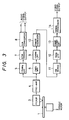
- Fig. 3 is a block diagram showing a preferred embodiment of a reproducing apparatus of the present invention applied to a video disk player by way of example.
- a video disk 1 acting as a recording medium is rotated by a spindle motor 2, and the information recorded on the video disk 1 is read by an optical pickup 3.
- a high frequency signal read by the pickup 3 is amplified by a pre-amplifier 4, and supplied to an LPF (low-pass filter) 5 having a cut-off frequency of 1.75 MHz, as well as to an HPF (high-pass filter) 6 having a cut-off frequency of 2 MHz.
- LPF low-pass filter
- HPF high-pass filter
- Phase distortion of the video FM signal caused by the LPF 9 is corrected by a phase equalizer 10 in the succeeding stage so as to obtain a signal having a flat phase characteristic.
- the resulting signal is in turn supplied to a video FM demodulator 11. (If the LPF 9 has a flat phase characteristic, it is not necessary to provide the phase equalizer 10.)
- Fig. 4 shows the frequency spectrum of the video FM signal, which is a high frequency signal band-limited by the LPF 9.
- the cut-off frequency of the LPF 9 higher than the white peak frequency (9.3 MHz) of the video FM signal and lower than a frequency in the vicinity of the lower side of the upper first sideband of the chroma signal.
- Fig. 5 shows the frequency spectrum of the video signal demodulated by the video FM demodulator 11 and in which unnecessary frequency components have been removed through an LPF12 having a cut-off frequency of 7 MHz.
- the high band portion of the luminance signal Y is reduced by about 6 dB, as may be seen from Fig. 5.
- the low band portion of the luminance signal Y is transmitted with both side bands and the high band portion of the luminance signal Y, including the chroma signal C, is transmitted with one side band.
- the foregoing problem can be alleviated if compensation is made to lower than low band of the frequency characteristic of the luminance signal Y by about 6 dB, as shown by a broken line in Fig. 5, with a characteristic compensation circuit 13 provided in the succeeding stage of the LPF 12.
- the same improvement as described above can be attained, alternatively, by effecting compensation so as to raise the high band of the luminance signal C, including the chroma signal C, by about 6 dB.
- the frequency of the video signal having such a spectrum with a level difference of 6 dB as shown in Fig. 5 varies up and down with respect to the APL (average picture level) of the video signal. That is, as seen from Fig. 4, the frequency reaches the minimum value of the white peak level and the maximum value at the blanking level.
- the frequency characteristic of the video signal can be made flat so that no peak nor notch is generated in the frequency characteristic, for example, if the APL level is continuously detected to thereby control the crossover frequency for improving the frequency characteristic of the characteristic compensation circuit 13.
- the video signal having a frequency characteristic improved by the characteristic compensation circuit 13 is outputted as the video output signal after signal processing, if desired, to superimpose a character signal or the like on the video signal in a signal processor 14.
- the cut-off frequency of the LPF 9 is set to the lower limit (10 MHz) of C+1 in the foregoing embodiment, the cut-off frequency may be selected to be a value lower than a frequency corresponding to the color subcarrier frequency in the vicinity of a lower limit of I1. In this case, however, a part of C+1 (the sideband at the lower frequency side) extends into the passband of the LPF 9 so that a signal at a frequency at which the level difference of 6 dB occurs in the spectrum of the video signal after demodulation is generated in the lower sideband of the chroma signal C (Fig. 5), thereby reducing the differential gain (DG) and differential phase (DP). Therefore, it is preferable to set the cut-off frequency of the LPF 9 at a value in a range for which substantially no reduction in the DG and the DP occurs.
- the LPF 9 having a cut-off frequency of, for example, 10 MHz is used to remove the upper sideband containing the interference spectrum in the foregoing embodiment
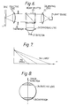
- the same cut-off characteristic as described above can be realized by suitably selecting the numerical aperture NA of an objective lens used in the pickup 3. That is, in an optical video disk system, laser light is used for reading the recorded information and an objective lens having an NA of 0.5 is generally used for focusing the laser light on the pits of a disk in the form of a light spot having a predetermined diameter.
- a low-pass filter is provided in a path of the read-out signal from the recording medium, and the cut-off frequency of the low-pass filter is selected to be higher than the white peak frequency of a video FM signal and lower than the color subcarrier frequency contained in the upper first sideband of the video FM signal.
- the present invention can be applied not only to a so-called broadband video disk system in which an analog audio FM signal is omitted, but also to a conventional Hi-Fi video disk system in which an analog audio FM signal is employed.
- a so-called broadband video disk system in which an analog audio FM signal is omitted
- a conventional Hi-Fi video disk system in which an analog audio FM signal is employed.
- Figure 6 shows a diaphragm 28 which is provided in an optical path between the objective lens 24 and the beam splitter 23, so as to set the value of NA in the direction of advance of the pick-up to 0.37.
- the pick-up also includes, as is conventional, a light source 21, collimating lens 22, converging lens 26 and detector 27, for reading information from the disk 1.
- Figure 8 illustrates the position of the diaphragm 28 as viewed from the disk 1.
Landscapes
- Engineering & Computer Science (AREA)
- Multimedia (AREA)
- Signal Processing (AREA)
- Signal Processing Not Specific To The Method Of Recording And Reproducing (AREA)
- Television Signal Processing For Recording (AREA)
- Optical Recording Or Reproduction (AREA)
Claims (8)
- Gerät zur Wiedergabe aufgezeichneter Informationen von einem Aufzeichnungsträger (1), auf dem ein frequenzmoduliertes Videosignal und ein digitales Audiosignal im Frequenzteilungs-Multiplexbetrieb aufgezeichnet sind, mit Hilfsmitteln (3) zum Lesen der auf dem Aufzeichnungsträger aufgezeichneten Signale, gekennzeichnet
durch ein Tiefpaßhilfsmittel (9; 28), das in einer Bahn eines von den Lesehilfsmitteln erzeugten Lesesignals vorgesehen ist,und dessen Grenzfrequenz höher als die Frequenz (Wp) der weißen Spitze des frequenzmodulierten Videosignals und niedriger als die Frequenz eines farbigen Hilfsträgers ist, der in einem ersten oberen Seitenband (C₊₁) des frequenzmodulierten Videosignals enthalten ist, und
durch eine Einrichtung (10 bis 14) zum Kompensieren der Frequenzcharakteristik des Signals, das an dem Ausgang des Tiefpaßhilfsmittels erzeugt und im wesentlichen demoduliert wird. - Gerät zur Wiedergabe von Informationen von einer Videoplatte gemäß Anspruch 1, bei dem das Tiefpaßhilfsmittel ein Objektiv (24), das in der Bahn eines von der Platte abgelesenen, optischen Signals angeordnet ist, und Mittel zur Einstellung der Öffnung des Objektivs enthält,um in der Breitenrichtung einer Plattenschreibspur eine erste numerische Öffnung (NA groß) und in der Laufrichtung der Schreibspur eine zweite numerische Öffnung (NA klein) zu erhalten,wobei die zweite numerische Öffnung (NA klein) geringer als die erste numerische Öffnung (NA groß) ist und die Grenzfrequenz des Tiefpaßhilfsmittels festlegt.
- Gerät gemäß Anspruch 2, bei dem die Mittel zur Einstellung des Objektivs eine Blende (28) enthalten, die neben dem Objektiv (24) angeordnet ist.
- Gerät gemäß Anspruch 3, bei dem die erste numerische Öffnung (NA groß) annähernd 0,5 und die zweite numerische Öffnung (NA klein) annähernd 0,37 beträgt.
- Gerät gemäß Anspruch 1, bei dem das Tiefpaßhilfsmittel ein elektronisches Filter (9) enthält.
- Gerät gemäß Anspruch 1 und ferner Anspruch 5 mit einem die Phase ausgleichenden Hilfsmittel (10), das in einer Stufe hinter dem Tiefpaßfilter zur Korrektur der Phasenverzerrung vorgesehen ist, die von dem Tiefpaßhilfsmittel verursacht ist.
- Gerät gemäß Anspruch 1 ferner mit einer die Charakteristik kompensierenden Schaltung (13), die in einer Stufe hinter einem für die Frequenzmodulation wirksamen Demodulator (11) vorgesehen ist, um ein Tiefband einer Frequenzcharakteristik eines in dem Lesesignal enthaltenen Luminanzsignals zu senken.
- Gerät gemäß Anspruch 1 ferner mit einer die Charakteristik kompensierenden Schaltung (13), die in einer Stufe hinter einem für die Frequenzmodulation wirksamen Demodulator (11) vorgesehen ist, um ein Hochband einer Frequenzcharakteristik eines Luminanzsignals anzuheben, das in dem Lesesignal enthalten ist.
Applications Claiming Priority (2)
| Application Number | Priority Date | Filing Date | Title |
|---|---|---|---|
| JP88199/87 | 1987-04-09 | ||
| JP62088199A JPH0832069B2 (ja) | 1987-04-09 | 1987-04-09 | 記録情報再生装置 |
Publications (3)
| Publication Number | Publication Date |
|---|---|
| EP0286452A2 EP0286452A2 (de) | 1988-10-12 |
| EP0286452A3 EP0286452A3 (en) | 1989-02-22 |
| EP0286452B1 true EP0286452B1 (de) | 1992-08-19 |
Family
ID=13936231
Family Applications (1)
| Application Number | Title | Priority Date | Filing Date |
|---|---|---|---|
| EP88303228A Expired EP0286452B1 (de) | 1987-04-09 | 1988-04-11 | Wiedergabegerät für aufgezeichnete Daten |
Country Status (4)
| Country | Link |
|---|---|
| US (1) | US4858024A (de) |
| EP (1) | EP0286452B1 (de) |
| JP (1) | JPH0832069B2 (de) |
| DE (1) | DE3873802T2 (de) |
Families Citing this family (8)
| Publication number | Priority date | Publication date | Assignee | Title |
|---|---|---|---|---|
| US5227891A (en) * | 1988-10-12 | 1993-07-13 | Sanyo Electric Co., Ltd. | Method of recording fine color video signal on optical recording media and method of reproducing thus recorded fine color video signal |
| JPH04206035A (ja) * | 1990-11-30 | 1992-07-28 | Kogaku Denshi Kk | Cd―romおよびcd―romの再生システム |
| US5835669A (en) * | 1995-06-28 | 1998-11-10 | Kabushiki Kaisha Toshiba | Multilingual recording medium which comprises frequency of use data/history data and a plurality of menus which are stored in a still picture format |
| EP0836192A1 (de) * | 1993-10-29 | 1998-04-15 | Kabushiki Kaisha Toshiba | Aufzeichnungsmedium für Mehrfachszenen, und Verfahren und Vorrichtung zur Wiedergabe von Daten davon |
| DE69318038T2 (de) * | 1993-10-29 | 1998-10-29 | Toshiba Kawasaki Kk | Aufzeichnungsmedium, das verschiedene sprachen verarbeiten kann und wiedergabevorrichtung |
| US5764846A (en) * | 1993-10-29 | 1998-06-09 | Kabushiki Kaisha Toshiba | Multi-scene recording medium and apparatus for reproducing data therefrom |
| US5784519A (en) * | 1995-06-15 | 1998-07-21 | Kabushiki Kaisha Toshiba | Multi-scene recording medium and apparatus for reproducing data therefrom |
| CN112601057B (zh) * | 2020-11-27 | 2023-03-03 | 浙江盛洋科技股份有限公司 | 一种c波段抗移动5g信号干扰装置 |
Family Cites Families (7)
| Publication number | Priority date | Publication date | Assignee | Title |
|---|---|---|---|---|
| NL7402692A (nl) * | 1974-02-28 | 1975-09-01 | Philips Nv | Kleurentelevisiesysteem. |
| JPS5266405A (en) * | 1975-11-29 | 1977-06-01 | Victor Co Of Japan Ltd | Optical recording system of information recording discs |
| JPS5356922A (en) * | 1976-11-01 | 1978-05-23 | Matsushita Electric Ind Co Ltd | Recording system of color television signal |
| CA1161946A (en) * | 1980-07-26 | 1984-02-07 | Sony Corporation | Method and apparatus for recording digitized information on a record medium |
| US4375096A (en) * | 1981-03-10 | 1983-02-22 | Rca Corporation | Multi-bandwidth optical playback apparatus with elongated read spot |
| JPS58190190A (ja) * | 1982-04-30 | 1983-11-07 | Victor Co Of Japan Ltd | 周波数変調波信号の二次歪低減装置 |
| JPH0634305B2 (ja) * | 1983-03-04 | 1994-05-02 | ソニー株式会社 | デイジタルデイスクによるデ−タ伝送システム |
-
1987
- 1987-04-09 JP JP62088199A patent/JPH0832069B2/ja not_active Expired - Lifetime
-
1988
- 1988-04-01 US US07/176,503 patent/US4858024A/en not_active Expired - Fee Related
- 1988-04-11 EP EP88303228A patent/EP0286452B1/de not_active Expired
- 1988-04-11 DE DE8888303228T patent/DE3873802T2/de not_active Expired - Fee Related
Also Published As
| Publication number | Publication date |
|---|---|
| EP0286452A3 (en) | 1989-02-22 |
| JPS63253789A (ja) | 1988-10-20 |
| EP0286452A2 (de) | 1988-10-12 |
| DE3873802T2 (de) | 1993-01-14 |
| DE3873802D1 (de) | 1992-09-24 |
| US4858024A (en) | 1989-08-15 |
| JPH0832069B2 (ja) | 1996-03-27 |
Similar Documents
| Publication | Publication Date | Title |
|---|---|---|
| EP0418852A2 (de) | Schaltung zur Verarbeitung eines Videosignals | |
| US4800446A (en) | Video disk recorded with video and digital data and recording/reproducing apparatus therefor | |
| EP0286452A2 (de) | Wiedergabegerät für aufgezeichnete Daten | |
| US5195073A (en) | Apparatus for selectively recording analog and digital data on an optical disc | |
| JPH0476191B2 (de) | ||
| EP0107295A2 (de) | Videoplatten-Aufzeichnungs- und Wiedergabesystem | |
| US5428455A (en) | Apparatus for reducing noise in high-frequency band | |
| US5227891A (en) | Method of recording fine color video signal on optical recording media and method of reproducing thus recorded fine color video signal | |
| JPS6252994B2 (de) | ||
| JPH0411424Y2 (de) | ||
| JP2608200B2 (ja) | 相違の映像システム間の再生時互換性を保持する輝度信号記録回路及びその方法 | |
| US5179476A (en) | Signal processor | |
| US4864427A (en) | Disk reproducing method and apparatus for disks with different video bandwidths | |
| JP3136597B2 (ja) | 記録再生装置 | |
| JP2576981B2 (ja) | 情報記録デイスク再生装置 | |
| JPS6118269B2 (de) | ||
| JP3381913B2 (ja) | 映像音声信号記録装置 | |
| JPS63133358A (ja) | 信号処理回路 | |
| JPS59115690A (ja) | 情報記録装置 | |
| JPH01144267A (ja) | 光ディスク再生装置 | |
| JPS6112195A (ja) | 記録再生方式 | |
| JPH0326951B2 (de) | ||
| JPS63312786A (ja) | 円盤状記録媒体の記録方式 | |
| JPH04366448A (ja) | 磁気記録再生装置 | |
| JPH0196868A (ja) | 記録情報再生装置 |
Legal Events
| Date | Code | Title | Description |
|---|---|---|---|
| PUAI | Public reference made under article 153(3) epc to a published international application that has entered the european phase |
Free format text: ORIGINAL CODE: 0009012 |
|
| AK | Designated contracting states |
Kind code of ref document: A2 Designated state(s): DE FR GB |
|
| PUAL | Search report despatched |
Free format text: ORIGINAL CODE: 0009013 |
|
| AK | Designated contracting states |
Kind code of ref document: A3 Designated state(s): DE FR GB |
|
| 17P | Request for examination filed |
Effective date: 19890727 |
|
| 17Q | First examination report despatched |
Effective date: 19910129 |
|
| GRAA | (expected) grant |
Free format text: ORIGINAL CODE: 0009210 |
|
| AK | Designated contracting states |
Kind code of ref document: B1 Designated state(s): DE FR GB |
|
| REF | Corresponds to: |
Ref document number: 3873802 Country of ref document: DE Date of ref document: 19920924 |
|
| ET | Fr: translation filed | ||
| PLBE | No opposition filed within time limit |
Free format text: ORIGINAL CODE: 0009261 |
|
| STAA | Information on the status of an ep patent application or granted ep patent |
Free format text: STATUS: NO OPPOSITION FILED WITHIN TIME LIMIT |
|
| 26N | No opposition filed | ||
| PGFP | Annual fee paid to national office [announced via postgrant information from national office to epo] |
Ref country code: GB Payment date: 19940405 Year of fee payment: 7 |
|
| PGFP | Annual fee paid to national office [announced via postgrant information from national office to epo] |
Ref country code: DE Payment date: 19940408 Year of fee payment: 7 |
|
| PGFP | Annual fee paid to national office [announced via postgrant information from national office to epo] |
Ref country code: FR Payment date: 19940411 Year of fee payment: 7 |
|
| PG25 | Lapsed in a contracting state [announced via postgrant information from national office to epo] |
Ref country code: GB Effective date: 19950411 |
|
| GBPC | Gb: european patent ceased through non-payment of renewal fee |
Effective date: 19950411 |
|
| PG25 | Lapsed in a contracting state [announced via postgrant information from national office to epo] |
Ref country code: FR Effective date: 19951229 |
|
| PG25 | Lapsed in a contracting state [announced via postgrant information from national office to epo] |
Ref country code: DE Effective date: 19960103 |
|
| REG | Reference to a national code |
Ref country code: FR Ref legal event code: ST |