EP0285878B1 - Dispositif de détection de rotation avec un synchro - Google Patents
Dispositif de détection de rotation avec un synchro Download PDFInfo
- Publication number
- EP0285878B1 EP0285878B1 EP88104278A EP88104278A EP0285878B1 EP 0285878 B1 EP0285878 B1 EP 0285878B1 EP 88104278 A EP88104278 A EP 88104278A EP 88104278 A EP88104278 A EP 88104278A EP 0285878 B1 EP0285878 B1 EP 0285878B1
- Authority
- EP
- European Patent Office
- Prior art keywords
- circuit
- counter
- rotational position
- time
- phase difference
- Prior art date
- Legal status (The legal status is an assumption and is not a legal conclusion. Google has not performed a legal analysis and makes no representation as to the accuracy of the status listed.)
- Expired - Lifetime
Links
Images


Classifications
-
- G—PHYSICS
- G01—MEASURING; TESTING
- G01P—MEASURING LINEAR OR ANGULAR SPEED, ACCELERATION, DECELERATION, OR SHOCK; INDICATING PRESENCE, ABSENCE, OR DIRECTION, OF MOVEMENT
- G01P3/00—Measuring linear or angular speed; Measuring differences of linear or angular speeds
- G01P3/42—Devices characterised by the use of electric or magnetic means
- G01P3/44—Devices characterised by the use of electric or magnetic means for measuring angular speed
-
- G—PHYSICS
- G01—MEASURING; TESTING
- G01D—MEASURING NOT SPECIALLY ADAPTED FOR A SPECIFIC VARIABLE; ARRANGEMENTS FOR MEASURING TWO OR MORE VARIABLES NOT COVERED IN A SINGLE OTHER SUBCLASS; TARIFF METERING APPARATUS; MEASURING OR TESTING NOT OTHERWISE PROVIDED FOR
- G01D5/00—Mechanical means for transferring the output of a sensing member; Means for converting the output of a sensing member to another variable where the form or nature of the sensing member does not constrain the means for converting; Transducers not specially adapted for a specific variable
- G01D5/12—Mechanical means for transferring the output of a sensing member; Means for converting the output of a sensing member to another variable where the form or nature of the sensing member does not constrain the means for converting; Transducers not specially adapted for a specific variable using electric or magnetic means
- G01D5/244—Mechanical means for transferring the output of a sensing member; Means for converting the output of a sensing member to another variable where the form or nature of the sensing member does not constrain the means for converting; Transducers not specially adapted for a specific variable using electric or magnetic means influencing characteristics of pulses or pulse trains; generating pulses or pulse trains
Definitions
- This invention relates to an apparatus for detecting a rotational position or a rotational speed of a rotary body such as a rotor of an electric motor.
- resolvers or selsyns, etc. are widely used for detection of revolution of electric motors because they are of the same structure as electric motors and have high reliability.
- a converter e.g., a synchro/digital converter (S/D converter), or a resolver/digital converter (R/D converter), etc.
- One system is a system called the tracking type converter.
- the tracking type converter For example, there are IS14, IS24, IS44 and IS64, etc. by ANALOG DEVICES Inc.
- an induced voltage signal having an amplitude determined by the sine-wave and cosine-wave functions corresponding to a rotational position is produced on the two-phase secondary winding.
- a sort of phase locked loop is constituted so that sine-wave and cosine-wave signals prepared by the count value of an up/down counter follow the amplitude of an induced voltage signal varying in a sinusoidal manner by changes in the rotational position.
- the other system is a system called the phase detection type converter.
- a sinusoidal induced voltage signal of which phase changes in accordance with the rotational position is produced on the secondary winding thereof.
- the rotational position is detected.
- This phase detection type converter is simple in the circuit configuration and most parts thereof are configured as a digital circuit, thus being realized at a low cost. With this system, however, the value detected is only updated every zero point of a secondary induced voltage of the synchro, so that when the rotational position changes, the detection period fluctuates in dependence upon the rotational speed. Accordingly, since it is impossible to establish synchronization with the sampling period for digital control, it is also difficult to apply this system to the digital control for electric motors.
- This invention has been made in view of the above and its object is to provide an apparatus for detecting revolution using a synchro which has solved fluctuation of the detection period, which is the drawback with the phase detection type converter, while effectively utilizing the merits of the circuit configuration of that converter, thus to be suited for digital control.
- an apparatus for detecting revolution using a synchro according to this invention is provided as claimed.
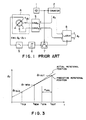
- this apparatus includes a clock generating circuit 1, a counter circuit 2, a function circuit 3, a synchro (resolver) 4, a filter circuit 5, a comparator circuit 6, a flip-flop circuit 7, and a latch circuit 8.
- Clock pulses output from the clock generating circuit 1 are counted by the counter circuit 2.
- the count value ⁇ 0 increases with time.
- This count value ⁇ 0 is input to the function circuit 3.
- This function circuit 3 may be constituted by a read only memory (ROM) into which e.g., sine-wave and cosine-wave functions are written, and a digital/analog converter.
- the synchro 4 is excited by the sine-wave signal output from the function circuit 3.
- an induced voltage signal sin (eo - e r ) of which phase with respect to the excitation sine-wave signal varies depending upon the rotational position e r is output from the secondary winding.
- the output from the synchro 4 passes through the filter circuit 5, whereby noises or distortion components are eliminated and are then input to the comparator circuit 6.
- a rectangular wave varying at zero points of the sine-wave of the induced voltage signal is output from the comparator circuit 6.
- a fall triggerable D-type flip-flop circuit 7 For latching at a good timing the count value ⁇ 0 of the counter circuit 2 which continues counting at all times, a fall triggerable D-type flip-flop circuit 7 is used.
- the output of the comparator circuit 6 is connected to the data input D of the flip-flop circuit 7 and the output of the clock generating circuit 1 is connected to the clock input CK of the flip-flop circuit 7.
- This circuit configuration permits the data input D to be subjected to sampling at the time of the fall of the clock pulse.
- a rectangular wave of which change time is synchronized with the time of the fall of the clock pulse is output from the flip-flop circuit 7.
- the rotational position e r can be detected as a digital value by the value latched by the latch circuit 8. It is to be noted that this value detected is a value updated at zero points of the secondary induced voltage of the synchro and such an update period fluctuates or changes depending upon revolving speed. For this reason, as previously described, there occurs the problem that synchronization with the sampling period is not established in the digital control, resulting in poor applicability to the digital control. Such a problem can be solved with an apparatus according to this invention which will be described below.
- This invention is based on a scheme to detect phase differences between an excitation signal of the synchro and an output induced voltage signal and to also detect times at which the phase differences have been detected, thus to perform a predictive computation of the rotational position at an arbitrary time by using these plural data detected.
- a circuit of a first embodiment of this invention will be described with reference to Fig. 2.
- This circuit includes the same circuit arrangement as in the conventional apparatus, which is comprised of excitation circuit comprising clock generating circuit 1, counter circuit 2, and function circuit 3 to generate an a.c. excitation signal, synchro (resolver) 4 having polyphase primary and secondary windings and coupled to a rotary body, filter circuit 5, comparator circuit 6, and flip-flop circuit 7.
- This circuit further includes, as new components, a phase difference detecting circuit comprising a latch circuit 9 and a counter circuit 10 to detect a phase difference and a detection time thereof, and a predictive computation circuit comprising latch circuits 11, 13, 14 and 15, a flip-flop circuit 12 and a microcomputer 16.
- These latch circuits 13, 14 and 15 are tristate output type capable of controlling an output.
- the clock pulses output from the clock generating circuit 1 are counted by the counter circuit 2.
- the count value eo increases with time.
- This count value ⁇ 0 is input to the function circuit 3.
- two-phase sine-wave signals sin ⁇ 0 and cos ⁇ 0 corresponding to the count value ⁇ 0 are output.
- the synchro (resolver) 4 is excited by the two-phase sine-wave signal output from the function circuit 3.
- an induced voltage signal sin ( ⁇ 0 - ⁇ r ) of which phase with respect to the excitation sine-wave signal varies depending upon the rotational position ⁇ r is output from the secondary winding.
- the output from the synchro 4 passes through the filter circuit 5 in the same manner as stated above, whereby noise or distortion components are eliminated therefrom.
- an output is changed to a rectangular wave varying at the zero point of the induced voltage signal through the comparator circuit 6 and the flip-flop circuit 7.
- the count value ⁇ 0 of the counter circuit 2 is latched by the latch circuit 9 to thereby detect a rotational position 9r as a phase difference between the excitation signal and the induced voltage signal.
- a count value ⁇ h of the high order counter 10 of the counter circuit 2 is also latched as data t h by the same latch circuit 9.
- the center dot is used as a divider between an upper order data and a lower order data in the specification) obtained as the combination of the upper order data t h and the lower order data or which have been latched by the latch circuit 9 represents the time at which the rotational position ⁇ r has been detected. Simultaneously with this, the data indicative of the previous rotational position and the data indicative of the detection time thereof which have been latched by the latch circuit 9 are transferred.
- the microcomputer 16 changes the data input D of the flip-flop circuit 12 from logic "0" to "1" at an arbitrary time as a command for reading these data thereinto.
- the output of the clock generating circuit 1 is connected to the clock input CK of the flip-flop circuit 12.
- the data input D is synchronized with the fall of the clock pulse, thus to be output from the flip-flop circuit 12.
- These latch circuits are provided for preventing the microcomputer 16 from reading thereinto data at the same time. The microcomputer 16 reads thereinto these data to perform a predictive computation.
- Fig. 3 The principle of the computation for predicting a rotational position is shown in Fig. 3 wherein the abscissa and the ordinate represent a time t and a rotational position er, respectively.
- the latest rotational position data latched by the latch circuit 14 is designated at ⁇ r NEW, the data indicative of the detection time thereof at t NEW , the data indicative of the rotational position one time before latched by the latch circuit 15 at ⁇ r OLD, the data indicative of the detection time thereof at to LD , and data indicative of the time when the microcomputer 16 has sent a command for reading thereinto data, which have been latched by the latch circuit 13, at t SYN .
- time t OUT is defined as indicated by the following equation (5):
- the microcomputer 16 executes the predictive computation shown in the equations (4) and (5), thus to output a predictive rotational position ⁇ r OUT at the time touT.
- a second embodiment of this invention is shown in Fig. 4. Since the digital control has a fixed sampling period in general, it is desirable that the detection period is fixed also when applied to the apparatus for detecting revolution. In this embodiment, the detection period is set to a fixed value equal to the excitation period.
- This embodiment differs from the first embodiment in that the flip-flop circuit 12 is not provided, that the latch circuit 13 latches only the count value 9 h of the counter circuit 10, and that the latch circuits 13 and 14 carry out the latch operation of the carry out C of the counter circuit 2.
- the latch circuits 13, 14 and 15 carry out the latch operation at an arbitrary time by a command from the microcomputer 16 in the first embodiment
- the carry output C of the counter circuit 2 of which period is the same as the excitation period is used as a latch command in this embodiment.
- the microcomputer 16 examines changes in the data of the latch circuit 13 and sequentially reads thereinto data of the latch circuits 13, 14 and 15 when any change occurs.
- the microcomputer 16 executes the predictive computation expressed as the equations (4) and (5) in the same manner as in the first embodiment, thus to output a predictive rotational position ⁇ r OUT at time touT.
- the period at which the microcomputer 16 outputs the predictive rotational position ⁇ r OUT becomes a fixed period equal to the excitation period.
- Fig. 5 shows a circuit additionally provided for conducting a predictive computation using three times of phase differences and their detection times.
- a latch circuit 17 is additionally connected to the output of the latch circuit 11 and a latch circuit 18 is further additionally connected to the output of the latch circuit 17.
- the predictive rotational position ⁇ r OUT at time tou T can be approximated by the following equation (9) when the speed from time t NEW to t OUT is designated at ⁇ r OUT:
- the microcomputer 16 executes the computation expressed by the equations (6) to (9) to output a predictive rotational position ⁇ r OUT at time tou T . Although the computation becomes complicated, a rotational position having a smaller error can be obtained.
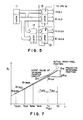
- a fourth embodiment of this invention is shown in Fig. 6.
- the circuit according to this embodiment is characterized in that a latch circuit 19, a rate multiplier circuit 20, and up/down counter circuit 21 are added to the circuit of the second embodiment shown in Fig. 4.
- the predictive computation circuit is composed of latch circuits 11, 13, 14 and 15, and microcomputer 16, thus to compute a predictive rotational position at time every fixed period.
- a value corresponding to a change in the predictive rotational position is further computed.
- the value corresponding to the change thus computed is applied as a rate input of the rate multiplier circuit 20.
- a pulse signal having a frequency corresponding to the rate input is output from the rate multiplier circuit 20.
- This pulse signal is counted by the up/down counter circuit 21.
- the count value of the up/down counter circuit 21 follows a predictive rotational position.
- a follow-up delay time and an advance time based on the predictive computation cancel with each other.
- the rotational position can be detected as a digital value by the count value of the up/down counter circuit 21 substantially without delay.
- the predictive computation in this circuit is performed as follows. Initially, the microcomputer 16 examines changes in data of the latch circuit 13. If there is any change, the microcomputer 16 reads thereinto these data to carry out a predictive computation. The principle of the computation for predicting a rotational computation is shown in Fig. 7 wherein the abscissa and the ordinate represent time t and rotational position er, respectively.
- the predictive rotational position erD is obtained by linear approximation from the rotational position e r OLD one time before and the detection time t OLD thereof, and the latest rotational position er NEW and the detection time t NEW thereof.
- the time tour is defined as indicated by the equation (11) by taking into consideration the time ⁇ CPU required for the predictive computation by the microcomputer 16 and the follow-up delay time ⁇ DLY :
- Such predictive computations are repeatedly executed every time data of the latch circuit 13 varies, i.e., in synchronism with the excitation period.
- the predictive rotational position ⁇ r D2 at time tc (t D2 ) has been similarly determined from the rotational position e r OLD2 further one time before and the detection time t OLD2 thereof, and the rotational position er OLD one time before and the detection time to LD thereof. Accordingly, the time ⁇ DLY from the time tc to the time t D is equal to the excitation period.
- equation (12) a change ⁇ rD in the predictive rotational position for this time is expressed by the following equation (12):
- the microcomputer 16 executes the predictive computation indicated by the equations (11) and (12) and the predictive rotation positional change computation indicated by the equation (12) and outputs at time tc the absolute value
- given as the rate input are output substantially equidistantly for the time ⁇ DLY .
- Such pulses are input to the clock of the up/down counter circuit 21.
- the count value e r e increases or decreases in dependence upon the sign SIGN given to the up/down input U/D. If the count value e r c is equal to the predictive rotational position e rD2 one time before at time tc, the count value ⁇ rC becomes equal to the predictive rotational position- ⁇ rD at time T D .
- the predictive rotational position and the count value ⁇ rC of the up/down counter circuit 21 coincide with each other every period equal to the excitation period.
- the count value ⁇ rC substantially linearly changes during respective periods as shown in Fig. 7.
- the latch circuit 19 is provided for adjusting an initial value of the count value of the up/down counter circuit 21.
- the microcomputer 16 reads thereinto the count value ⁇ rC of the up/down counter circuit 21 through the latch circuit 19, thus to operate the rate input of the rate multiplier circuit 20 so as to become equal to a value detected of the rotational position.
- the count value of the up/down counter circuit follows the rotational position substantially without delay.
- continuous rotational positions can be obtained as digital values.
- microcomputer 16 it is not required for the microcomputer 16 to allow the computational period to be in correspondence with the excitation period, but an arrangement such that the computational period is arbitrary may be employed.
- the restriction of detection period and/or changes or fluctuations in the detection period depending upon revolving speed, etc. which have been the drawbacks with a conventional apparatus for detecting revolution comprised of combination of the synchro and the phase detection type converter, are eliminated, whereby detection at an arbitrary time and detection every fixed period can be made. Accordingly, even when an apparatus for detecting revolution according to this invention is used for digital control of an electric motor, synchronization between the sampling period for the digital control and the detection period can be readily established. Further, when applied to the multiple-speed synchro, rotational positions at the same time of plural synchros can be detected and synthesis of values detected is facilitated even when the revolving speed is high. In addition, since most of circuits constituting this apparatus are of the digital circuit configuration, an implementation as an integrated circuit is possible, resulting in realization of manufacture of a small-sized and low cost apparatus.
Landscapes
- Physics & Mathematics (AREA)
- General Physics & Mathematics (AREA)
- Transmission And Conversion Of Sensor Element Output (AREA)
Claims (6)
Applications Claiming Priority (4)
| Application Number | Priority Date | Filing Date | Title |
|---|---|---|---|
| JP61217/87 | 1987-03-18 | ||
| JP6121887A JPH0781879B2 (ja) | 1987-03-18 | 1987-03-18 | 回転検出装置 |
| JP61218/87 | 1987-03-18 | ||
| JP6121787A JPH0781878B2 (ja) | 1987-03-18 | 1987-03-18 | 回転検出装置 |
Publications (2)
| Publication Number | Publication Date |
|---|---|
| EP0285878A1 EP0285878A1 (fr) | 1988-10-12 |
| EP0285878B1 true EP0285878B1 (fr) | 1990-08-01 |
Family
ID=26402264
Family Applications (1)
| Application Number | Title | Priority Date | Filing Date |
|---|---|---|---|
| EP88104278A Expired - Lifetime EP0285878B1 (fr) | 1987-03-18 | 1988-03-17 | Dispositif de détection de rotation avec un synchro |
Country Status (4)
| Country | Link |
|---|---|
| US (1) | US4837492A (fr) |
| EP (1) | EP0285878B1 (fr) |
| KR (1) | KR910003518B1 (fr) |
| DE (1) | DE3860375D1 (fr) |
Families Citing this family (10)
| Publication number | Priority date | Publication date | Assignee | Title |
|---|---|---|---|---|
| JPH0744864B2 (ja) * | 1989-05-22 | 1995-05-15 | シャープ株式会社 | Pll速度制御回路 |
| US5455498A (en) * | 1990-05-09 | 1995-10-03 | Omron Corporation | Angle of rotation detector |
| US5406155A (en) * | 1992-06-03 | 1995-04-11 | Trw Inc. | Method and apparatus for sensing relative position between two relatively rotatable members |
| JP2003235285A (ja) * | 2002-02-08 | 2003-08-22 | Denso Corp | 三相ブラシレスdcモータの回転方向検出装置 |
| JP4240195B2 (ja) * | 2002-07-03 | 2009-03-18 | 株式会社安川電機 | エンコーダ検出位置データのビット誤り検出・推定方法およびエンコーダビット誤り検出・推定機能付acサーボドライバ並びにモータ |
| DE102009019509B4 (de) * | 2009-04-24 | 2011-06-09 | Lenze Automation Gmbh | Verfahren und Vorrichtung zum Bestimmen eines Rotorwinkels einer rotierenden Welle |
| JP2013034364A (ja) * | 2011-06-29 | 2013-02-14 | Panasonic Corp | インバータ制御装置およびこれを用いた電動圧縮機、並びに電気機器 |
| JP6207223B2 (ja) * | 2013-05-01 | 2017-10-04 | キヤノン株式会社 | モータ駆動装置およびその制御方法 |
| EP2835616A1 (fr) | 2013-08-09 | 2015-02-11 | Ams Ag | Dispositif de capteur de position pour déterminer une position d'un dispositif mobile |
| WO2018021043A1 (fr) * | 2016-07-27 | 2018-02-01 | パナソニックIpマネジメント株式会社 | Moteur en cc sans balais |
Family Cites Families (8)
| Publication number | Priority date | Publication date | Assignee | Title |
|---|---|---|---|---|
| FR1150615A (fr) * | 1956-05-17 | 1958-01-16 | Ibm France | Commande d'un servomécanisme à partir d'un calculateur numérique à mémoire |
| US4023085A (en) * | 1975-08-06 | 1977-05-10 | General Electric Company | Numerical control system having a digitized phase loop |
| US4358722A (en) * | 1977-08-17 | 1982-11-09 | Kabushiki Kaisha Yaskawa Denki Seisakusho | Speed detector using resolver |
| US4346334A (en) * | 1980-07-23 | 1982-08-24 | Brother Kogyo Kabushiki Kaisha | DC Servomotor system |
| JPS5733355A (en) * | 1980-08-06 | 1982-02-23 | Toshiba Corp | Digital speed detector |
| JPS5988612A (ja) * | 1982-11-15 | 1984-05-22 | Toshiba Mach Co Ltd | アブソリユ−ト位置の検知方法および装置 |
| US4518905A (en) * | 1983-05-16 | 1985-05-21 | Rockwell International Corporation | Current control of synchro power amplifiers |
| US4677138A (en) * | 1983-10-19 | 1987-06-30 | Yeda Research And Development Co., Ltd. | High yield process for producing polyaldehyde microspheres |
-
1988
- 1988-03-17 DE DE8888104278T patent/DE3860375D1/de not_active Expired - Lifetime
- 1988-03-17 EP EP88104278A patent/EP0285878B1/fr not_active Expired - Lifetime
- 1988-03-18 US US07/169,977 patent/US4837492A/en not_active Expired - Lifetime
- 1988-03-18 KR KR1019880002865A patent/KR910003518B1/ko not_active IP Right Cessation
Also Published As
| Publication number | Publication date |
|---|---|
| KR890015024A (ko) | 1989-10-28 |
| US4837492A (en) | 1989-06-06 |
| DE3860375D1 (de) | 1990-09-06 |
| EP0285878A1 (fr) | 1988-10-12 |
| KR910003518B1 (ko) | 1991-06-03 |
Similar Documents
| Publication | Publication Date | Title |
|---|---|---|
| US4527120A (en) | System for converting mechanical movement to a digital signal | |
| CA1270542A (fr) | Methode et dispositif pour corriger les erreurs d'un resolver | |
| US4669024A (en) | Multiphase frequency selective phase locked loop with multiphase sinusoidal and digital outputs | |
| EP0285878B1 (fr) | Dispositif de détection de rotation avec un synchro | |
| US4282468A (en) | High speed position feedback and comparator system | |
| EP0331189B1 (fr) | Méthode et dispositif de détection de position et/ou vitesse | |
| GB1559457A (en) | Absolute resolver digitzer | |
| US6552666B1 (en) | Phase difference detection device and method for a position detector | |
| US5815424A (en) | Digital angle conversion method | |
| EP0165046B1 (fr) | Générateur d'impulsions pour produire un train d impulsions représentant le deplacement d un corps | |
| US3255448A (en) | Angular displacement phase shift encoder analog to digital converter | |
| KR0155878B1 (ko) | 리니어 스텝핑 모터의 위치검출방법 및 그 장치 | |
| US4734655A (en) | Digital rotation detecting apparatus | |
| JPH0781879B2 (ja) | 回転検出装置 | |
| JPS63229320A (ja) | 回転検出装置 | |
| US4321684A (en) | Digital resolver | |
| JP3365913B2 (ja) | 位置検出装置 | |
| US3997893A (en) | Synchro digitizer | |
| JPS61207920A (ja) | レゾルバ回転検出器 | |
| JP2606999B2 (ja) | レゾルバ信号の接続装置 | |
| US5136226A (en) | Correlated coarse position error processor | |
| JPH0466288B2 (fr) | ||
| SU682872A1 (ru) | Цифрова след ща система | |
| JPS6038616A (ja) | 位相信号−インクリメンタル信号変換器 | |
| JPH0511458Y2 (fr) |
Legal Events
| Date | Code | Title | Description |
|---|---|---|---|
| PUAI | Public reference made under article 153(3) epc to a published international application that has entered the european phase |
Free format text: ORIGINAL CODE: 0009012 |
|
| 17P | Request for examination filed |
Effective date: 19880414 |
|
| AK | Designated contracting states |
Kind code of ref document: A1 Designated state(s): DE FR GB SE |
|
| 17Q | First examination report despatched |
Effective date: 19891123 |
|
| GRAA | (expected) grant |
Free format text: ORIGINAL CODE: 0009210 |
|
| AK | Designated contracting states |
Kind code of ref document: B1 Designated state(s): DE FR GB SE |
|
| REF | Corresponds to: |
Ref document number: 3860375 Country of ref document: DE Date of ref document: 19900906 |
|
| ET | Fr: translation filed | ||
| PLBE | No opposition filed within time limit |
Free format text: ORIGINAL CODE: 0009261 |
|
| STAA | Information on the status of an ep patent application or granted ep patent |
Free format text: STATUS: NO OPPOSITION FILED WITHIN TIME LIMIT |
|
| 26N | No opposition filed | ||
| PGFP | Annual fee paid to national office [announced via postgrant information from national office to epo] |
Ref country code: FR Payment date: 19940310 Year of fee payment: 7 |
|
| EAL | Se: european patent in force in sweden |
Ref document number: 88104278.2 |
|
| PGFP | Annual fee paid to national office [announced via postgrant information from national office to epo] |
Ref country code: GB Payment date: 19950307 Year of fee payment: 8 |
|
| PG25 | Lapsed in a contracting state [announced via postgrant information from national office to epo] |
Ref country code: FR Free format text: LAPSE BECAUSE OF NON-PAYMENT OF DUE FEES Effective date: 19951130 |
|
| PG25 | Lapsed in a contracting state [announced via postgrant information from national office to epo] |
Ref country code: GB Effective date: 19960317 |
|
| REG | Reference to a national code |
Ref country code: FR Ref legal event code: ST |
|
| GBPC | Gb: european patent ceased through non-payment of renewal fee |
Effective date: 19960317 |
|
| PGFP | Annual fee paid to national office [announced via postgrant information from national office to epo] |
Ref country code: SE Payment date: 20050304 Year of fee payment: 18 |
|
| PGFP | Annual fee paid to national office [announced via postgrant information from national office to epo] |
Ref country code: DE Payment date: 20050310 Year of fee payment: 18 |
|
| PG25 | Lapsed in a contracting state [announced via postgrant information from national office to epo] |
Ref country code: SE Free format text: LAPSE BECAUSE OF NON-PAYMENT OF DUE FEES Effective date: 20060318 |
|
| PG25 | Lapsed in a contracting state [announced via postgrant information from national office to epo] |
Ref country code: DE Free format text: LAPSE BECAUSE OF NON-PAYMENT OF DUE FEES Effective date: 20061003 |
|
| EUG | Se: european patent has lapsed |