EP0284792B1 - Remorque auto-chargeuse - Google Patents
Remorque auto-chargeuse Download PDFInfo
- Publication number
- EP0284792B1 EP0284792B1 EP88103038A EP88103038A EP0284792B1 EP 0284792 B1 EP0284792 B1 EP 0284792B1 EP 88103038 A EP88103038 A EP 88103038A EP 88103038 A EP88103038 A EP 88103038A EP 0284792 B1 EP0284792 B1 EP 0284792B1
- Authority
- EP
- European Patent Office
- Prior art keywords
- cutting frame
- loading
- knives
- loading waggon
- supporting
- Prior art date
- Legal status (The legal status is an assumption and is not a legal conclusion. Google has not performed a legal analysis and makes no representation as to the accuracy of the status listed.)
- Expired - Lifetime
Links
- 239000004459 forage Substances 0.000 title abstract 4
- 238000012423 maintenance Methods 0.000 abstract 2
- 230000002349 favourable effect Effects 0.000 description 3
- 238000003306 harvesting Methods 0.000 description 2
- 241000599985 Beijerinckia mobilis Species 0.000 description 1
- 230000001419 dependent effect Effects 0.000 description 1
- 230000008439 repair process Effects 0.000 description 1
Images

Classifications
-
- A—HUMAN NECESSITIES
- A01—AGRICULTURE; FORESTRY; ANIMAL HUSBANDRY; HUNTING; TRAPPING; FISHING
- A01D—HARVESTING; MOWING
- A01D90/00—Vehicles for carrying harvested crops with means for selfloading or unloading
- A01D90/02—Loading means
- A01D90/04—Loading means with additional cutting means
-
- A—HUMAN NECESSITIES
- A01—AGRICULTURE; FORESTRY; ANIMAL HUSBANDRY; HUNTING; TRAPPING; FISHING
- A01F—PROCESSING OF HARVESTED PRODUCE; HAY OR STRAW PRESSES; DEVICES FOR STORING AGRICULTURAL OR HORTICULTURAL PRODUCE
- A01F15/00—Baling presses for straw, hay or the like
- A01F15/08—Details
- A01F15/10—Feeding devices for the crop material e.g. precompression devices
- A01F2015/107—Means for withdrawing knives, rotor or walls of the feeding chamber in case of plugging or congestion
Definitions
- the invention relates to a loading wagon with the features of the preamble of claim 1.
- the invention is therefore based on the object of avoiding these disadvantages and of creating a loading wagon of the type mentioned, in which the grinding of the knives is possible with little expenditure of time in an ergonomically favorable position of the operator.
- the three or four wheels required for secure support and transport can remain permanently on the cutting frame, so that the removal of the cutting frame can be done in seconds by the quick-release fasteners. This time is brought back several times by the comfortable working posture and favorable working conditions. Further advantageous embodiments are the subject of the dependent claims and the drawings.
- a loading wagon 1 is partially shown, in which the feed material picked up from the ground is conveyed through the conveying channel 2 into the loading space.
- the knives 3 protrude into the conveying channel 2 and are attached to the cutting frame 5 by means of overload protection devices, not shown.
- the supporting elements are designated by 6, which can be designed according to FIG. 2 as support wheels 7 or according to FIG. 3 as a sliding guide 12.
- quick-release fasteners 8 are shown, which here, for. B. are designed as a bolt / catch hook connection.
- the entire cutting frame 5 can easily be moved laterally under the Loader wagons 1 are pulled out. If necessary, the cutting frame can be transported to the farm workshop or the knives can be reground next to the loading wagon. In this grinding position 5 ⁇ of the cutting frame 5, the knives 3 can be reached from the front without being restricted by the loading wagon, so that the operator can grind the knives 3 in an ergonomically favorable position.
- a guide 10 can also be attached to the cutting frame 5, so that the grinding angle of the knives remains constant, since the mounted grinding device 11 is guided exactly.
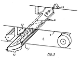
- FIG. 3 A further embodiment of the invention is shown schematically in FIG. 3.
- the cutting frame 5 is first pivoted downward by about 30 ° about the front circular sliding guide 12 by means of the pivot lever 14, so that the knives 3 no longer protrude into the conveying channel 2 and then laterally after releasing a locking device, not shown, z. B. pulled out on handles 9.
- the cutting frame 5 can be pulled out completely so that all knives 3 are accessible.
- a grinding device 11 can be fastened above the cutting frame 5 at a pivot point 13 on the side of the loading wagon 1, so that the cutting frame 5 can be pulled out step by step by a knife distance or, if necessary, turned out with a crank (not shown), one knife in each case is ground.
- the cutting frame 5 can form a component together with the bottom plate of the conveying channel 2, the drawer-like pulling out of the cutting frame 5 no longer having to be pivoted downwards, but only need to be shifted laterally, provided the knives 3 are each between two conveying rakes the conveyor are slidable.
- This design is particularly suitable for loader wagons with a few continuous conveyor rakes or for loader wagons with only one row of knives, since such one can also be moved transversely even with closely spaced conveyor rakes, possibly only in a certain rotational position of the conveyor device.
- z. B simpler U-profiles can be used.
Landscapes
- Life Sciences & Earth Sciences (AREA)
- Environmental Sciences (AREA)
- Harvester Elements (AREA)
- Disintegrating Or Milling (AREA)
Claims (10)
- Chargeuse mobile, avec un canal d'acheminement, dans lequel pénètrent un certain nombre de lames (3) en position de service et sur le côté arrière duquel est disposé, dans un espace libre (4) en dessous de la chargeuse mobile, au moins un bâti de coupe (5) qui porte les lames, qui s'étend sur la largeur du canal d'acheminement et qui peut être déplacé à une position d'affûtage, caractérisée en ce que le bâti de coupe (5) est conçu avec possibilité de translation latérale sur des éléments de soutien (6), et peut être sorti de l'espace libre (4) pour être amené à une position d'affûtage d'accès facile (5'), à côté de la chargeuse mobile (1).
- Chargeuse mobile selon la revendication 1, caractérisée en ce que des roues de soutien (7) sont prévues comme éléments de soutien (6) et le bâti de coupe (5) peut être détaché de la chargeuse mobile (1) à l'aide d'accouplements rapides (8).
- Chargeuse mobile selon la revendication 2, caractérisée en ce que les roues de soutien (7) peuvent être rapportées en vue du déplacement en position d'affûtage (5').
- Chargeuse mobile selon la revendication 2, caractérisée en ce que les roues de soutien (7) sont disposées fixement sur le bâti de coupe (5).
- Chargeuse mobile selon la revendication 1, caractérisée en ce que des poignées (9) sont prévues sur le bâti de coupe (5).
- Chargeuse mobile selon la revendication 2, caractérisée en ce qu'au moins une roue de soutien (7) est réalisée dirigeable.
- Chargeuse mobile selon la revendication 2, caractérisée en ce qu'il est prévu sur le bâti de coupe (5) au moins un guide (10) qui s'étend perpendiculairement à l'orientation des lames et sur lequel peut être monté un appareil d'affûtage (11).
- Chargeuse mobile selon la revendication 1, caractérisée en ce que les éléments de soutien (6) sont constitués par des glissières (12) s'étendant sur la largeur du canal d'acheminement (2), sur lesquelles le bâti de coupe (5) peut être déplacé à la position d'affûtage (5') à la manière d'un tiroir.
- Chargeuse mobile selon la revendication 8, caractérisée en ce qu'un appareil d'affûtage (11) peut être fixé en un point d'articulation (13) sur le côté de la chargeuse mobile (1) et est disposé avec possibilité de pivotement dans le plan vertical respectif des différentes lames (3).
- Chargeuse mobile selon la revendication 8, caractérisée en ce que les rayons de courbure des tranchants des lames (3) correspondent à la trajectoire de déplacement de l'appareil d'affûtage (11) autour du point d'articulation (13).
Priority Applications (1)
| Application Number | Priority Date | Filing Date | Title |
|---|---|---|---|
| AT88103038T ATE67064T1 (de) | 1987-04-03 | 1988-03-01 | Ladewagen. |
Applications Claiming Priority (2)
| Application Number | Priority Date | Filing Date | Title |
|---|---|---|---|
| DE3711355 | 1987-04-03 | ||
| DE3711355A DE3711355C1 (de) | 1987-04-03 | 1987-04-03 | Ladewagen |
Publications (2)
| Publication Number | Publication Date |
|---|---|
| EP0284792A1 EP0284792A1 (fr) | 1988-10-05 |
| EP0284792B1 true EP0284792B1 (fr) | 1991-09-11 |
Family
ID=6324853
Family Applications (1)
| Application Number | Title | Priority Date | Filing Date |
|---|---|---|---|
| EP88103038A Expired - Lifetime EP0284792B1 (fr) | 1987-04-03 | 1988-03-01 | Remorque auto-chargeuse |
Country Status (3)
| Country | Link |
|---|---|
| EP (1) | EP0284792B1 (fr) |
| AT (1) | ATE67064T1 (fr) |
| DE (1) | DE3711355C1 (fr) |
Families Citing this family (7)
| Publication number | Priority date | Publication date | Assignee | Title |
|---|---|---|---|---|
| DE9308656U1 (de) * | 1993-06-09 | 1993-08-12 | Alois Pöttinger Maschinenfabrik Ges.m.b.H., Grieskirchen | Erntemaschine mit Schneidwerk |
| DE102006036199B4 (de) * | 2006-08-03 | 2016-01-07 | Deere & Company | Förderzusammenbau und Presse |
| DE102010050584A1 (de) * | 2010-11-05 | 2012-05-10 | Alois Pöttinger Maschinenfabrik Gmbh | Erntemaschine |
| DE102012109773A1 (de) * | 2012-05-03 | 2013-11-07 | Usines Claas France S.A.S. | Erntemaschine mit einer Schneidvorrichtung |
| DE102012008721A1 (de) * | 2012-05-03 | 2013-11-07 | Usines Claas France S.A.S. | Erntemaschine mit einer Schneidevorrichtung |
| NL2010354C2 (en) * | 2013-02-22 | 2014-08-25 | Forage Innovations Bv | Conveying arrangement with knives which can be pivoted vertically and shifted laterally. |
| EP4374682A1 (fr) * | 2022-11-23 | 2024-05-29 | CNH Industrial Belgium N.V. | Machine de récolte |
Family Cites Families (4)
| Publication number | Priority date | Publication date | Assignee | Title |
|---|---|---|---|---|
| DE1928261U (de) * | 1965-09-01 | 1965-12-02 | Elise Tebbe Machinen Und Fahrz | Landwirtschaftlichez ladewagen mit schneidvorrichtung. |
| DE1954212U (de) * | 1966-08-30 | 1967-01-26 | Steinkuhle Kg Friedr | Landwirtschaftliches ladefahrzeug. |
| DE3028306C2 (de) * | 1980-07-25 | 1986-01-30 | ALOIS PöTTINGER MASCHINENFABRIK GMBH, GRIESKIRCHEN | Scneidwerk für landwirtschaftliche Geräte, insbesondere Selbstladewagen |
| DE3323116C2 (de) * | 1983-06-27 | 1985-11-07 | Klöckner-Humboldt-Deutz AG Zweigniederlassung Fahr, 7702 Gottmadingen | Ladewagen mit Schleifeinrichtung |
-
1987
- 1987-04-03 DE DE3711355A patent/DE3711355C1/de not_active Expired
-
1988
- 1988-03-01 AT AT88103038T patent/ATE67064T1/de not_active IP Right Cessation
- 1988-03-01 EP EP88103038A patent/EP0284792B1/fr not_active Expired - Lifetime
Also Published As
| Publication number | Publication date |
|---|---|
| ATE67064T1 (de) | 1991-09-15 |
| EP0284792A1 (fr) | 1988-10-05 |
| DE3711355C1 (de) | 1988-04-28 |
Similar Documents
| Publication | Publication Date | Title |
|---|---|---|
| DE1949978A1 (de) | Universalschlepper | |
| EP0073360B1 (fr) | Faucheuse | |
| DE3134389A1 (de) | Maehmaschine | |
| DE2834197C2 (de) | Geräteträger | |
| EP0284792B1 (fr) | Remorque auto-chargeuse | |
| DE3028306C2 (de) | Scneidwerk für landwirtschaftliche Geräte, insbesondere Selbstladewagen | |
| EP0066238B1 (fr) | Récolteuse pour récolter des denrées arrangées en files | |
| DE2412461C3 (de) | Feldhäcksler | |
| EP0204967B1 (fr) | Remorque chargeuse pourvue d'un dispositif d'affûtage | |
| DE1930687B2 (de) | Abladevorrichtung fuer eine fahrbare baumbearbeitungsmaschine | |
| DE8709233U1 (de) | Kreiselheuwerbungsmaschine | |
| DE69605466T2 (de) | Zustreichvorrichtung für eine Sämaschine | |
| EP0105055B1 (fr) | Véhicule pour le transport d'un dispositif de récolte | |
| DE570506C (de) | Baumwollerntemaschine | |
| CH674441A5 (fr) | ||
| DE1130644B (de) | Maehdrescher mit angebauter Strohpresse | |
| DE69228637T2 (de) | Gerät zum Mähen von stehendem Getreide | |
| DE202011100212U1 (de) | Anhänger, insbesondere für den Transport von Holz | |
| AT390547B (de) | Geraet zum herausschneiden, aufnehmen und aufloesen von futterbloecken aus flachsilos | |
| DE4220776C1 (de) | Flachsiloschneid- und Übergabegerät | |
| DE3625514C2 (fr) | ||
| AT377412B (de) | Schneidwerk fuer landwirtschftliche geraete, insbesondere selbstladewagen | |
| AT346636B (de) | Maehmaschine | |
| DE1205334B (de) | Gezogenes Geraet, insbesondere Feldhaecksler | |
| AT209619B (de) | Vorrichtung zum seitlichen Versetzen des am Boden liegenden Erntegutes |
Legal Events
| Date | Code | Title | Description |
|---|---|---|---|
| PUAI | Public reference made under article 153(3) epc to a published international application that has entered the european phase |
Free format text: ORIGINAL CODE: 0009012 |
|
| AK | Designated contracting states |
Kind code of ref document: A1 Designated state(s): AT BE CH FR IT LI NL |
|
| 17P | Request for examination filed |
Effective date: 19881216 |
|
| 17Q | First examination report despatched |
Effective date: 19900627 |
|
| RAP1 | Party data changed (applicant data changed or rights of an application transferred) |
Owner name: KARL MENGELE & SOEHNE, MASCHINENFABRIKEN GMBH & CO |
|
| GRAA | (expected) grant |
Free format text: ORIGINAL CODE: 0009210 |
|
| AK | Designated contracting states |
Kind code of ref document: B1 Designated state(s): AT BE CH FR IT LI NL |
|
| PG25 | Lapsed in a contracting state [announced via postgrant information from national office to epo] |
Ref country code: IT Free format text: LAPSE BECAUSE OF FAILURE TO SUBMIT A TRANSLATION OF THE DESCRIPTION OR TO PAY THE FEE WITHIN THE PRE;WARNING: LAPSES OF ITALIAN PATENTS WITH EFFECTIVE DATE BEFORE 2007 MAY HAVE OCCURRED AT ANY TIME BEFORE 2007. THE CORRECT EFFECTIVE DATE MAY BE DIFFERENT FROM THE ONE RECORDED.SCRIBED TIME-LIMIT Effective date: 19910911 |
|
| REF | Corresponds to: |
Ref document number: 67064 Country of ref document: AT Date of ref document: 19910915 Kind code of ref document: T |
|
| EN | Fr: translation not filed | ||
| PG25 | Lapsed in a contracting state [announced via postgrant information from national office to epo] |
Ref country code: FR Effective date: 19920131 |
|
| PGFP | Annual fee paid to national office [announced via postgrant information from national office to epo] |
Ref country code: BE Payment date: 19920327 Year of fee payment: 5 |
|
| PGFP | Annual fee paid to national office [announced via postgrant information from national office to epo] |
Ref country code: CH Payment date: 19920331 Year of fee payment: 5 Ref country code: NL Payment date: 19920331 Year of fee payment: 5 |
|
| PGFP | Annual fee paid to national office [announced via postgrant information from national office to epo] |
Ref country code: AT Payment date: 19920428 Year of fee payment: 5 |
|
| PLBE | No opposition filed within time limit |
Free format text: ORIGINAL CODE: 0009261 |
|
| STAA | Information on the status of an ep patent application or granted ep patent |
Free format text: STATUS: NO OPPOSITION FILED WITHIN TIME LIMIT |
|
| 26N | No opposition filed | ||
| REG | Reference to a national code |
Ref country code: FR Ref legal event code: ST |
|
| PG25 | Lapsed in a contracting state [announced via postgrant information from national office to epo] |
Ref country code: AT Effective date: 19930301 |
|
| PG25 | Lapsed in a contracting state [announced via postgrant information from national office to epo] |
Ref country code: CH Effective date: 19930331 Ref country code: BE Effective date: 19930331 Ref country code: LI Effective date: 19930331 |
|
| BERE | Be: lapsed |
Owner name: KARL MENGELE & SOHNE MASCHINENFABRIKEN G.M.B.H. & Effective date: 19930331 |
|
| PG25 | Lapsed in a contracting state [announced via postgrant information from national office to epo] |
Ref country code: NL Effective date: 19931001 |
|
| NLV4 | Nl: lapsed or anulled due to non-payment of the annual fee | ||
| REG | Reference to a national code |
Ref country code: CH Ref legal event code: PL |