EP0284792B1 - Self-loading forage box - Google Patents
Self-loading forage box Download PDFInfo
- Publication number
- EP0284792B1 EP0284792B1 EP88103038A EP88103038A EP0284792B1 EP 0284792 B1 EP0284792 B1 EP 0284792B1 EP 88103038 A EP88103038 A EP 88103038A EP 88103038 A EP88103038 A EP 88103038A EP 0284792 B1 EP0284792 B1 EP 0284792B1
- Authority
- EP
- European Patent Office
- Prior art keywords
- cutting frame
- loading
- knives
- loading waggon
- supporting
- Prior art date
- Legal status (The legal status is an assumption and is not a legal conclusion. Google has not performed a legal analysis and makes no representation as to the accuracy of the status listed.)
- Expired - Lifetime
Links
- 239000004459 forage Substances 0.000 title abstract 4
- 238000012423 maintenance Methods 0.000 abstract 2
- 230000002349 favourable effect Effects 0.000 description 3
- 238000003306 harvesting Methods 0.000 description 2
- 241000599985 Beijerinckia mobilis Species 0.000 description 1
- 230000001419 dependent effect Effects 0.000 description 1
- 230000008439 repair process Effects 0.000 description 1
Images

Classifications
-
- A—HUMAN NECESSITIES
- A01—AGRICULTURE; FORESTRY; ANIMAL HUSBANDRY; HUNTING; TRAPPING; FISHING
- A01D—HARVESTING; MOWING
- A01D90/00—Vehicles for carrying harvested crops with means for selfloading or unloading
- A01D90/02—Loading means
- A01D90/04—Loading means with additional cutting means
-
- A—HUMAN NECESSITIES
- A01—AGRICULTURE; FORESTRY; ANIMAL HUSBANDRY; HUNTING; TRAPPING; FISHING
- A01F—PROCESSING OF HARVESTED PRODUCE; HAY OR STRAW PRESSES; DEVICES FOR STORING AGRICULTURAL OR HORTICULTURAL PRODUCE
- A01F15/00—Baling presses for straw, hay or the like
- A01F15/08—Details
- A01F15/10—Feeding devices for the crop material e.g. precompression devices
- A01F2015/107—Means for withdrawing knives, rotor or walls of the feeding chamber in case of plugging or congestion
Definitions
- the invention relates to a loading wagon with the features of the preamble of claim 1.
- the invention is therefore based on the object of avoiding these disadvantages and of creating a loading wagon of the type mentioned, in which the grinding of the knives is possible with little expenditure of time in an ergonomically favorable position of the operator.
- the three or four wheels required for secure support and transport can remain permanently on the cutting frame, so that the removal of the cutting frame can be done in seconds by the quick-release fasteners. This time is brought back several times by the comfortable working posture and favorable working conditions. Further advantageous embodiments are the subject of the dependent claims and the drawings.
- a loading wagon 1 is partially shown, in which the feed material picked up from the ground is conveyed through the conveying channel 2 into the loading space.
- the knives 3 protrude into the conveying channel 2 and are attached to the cutting frame 5 by means of overload protection devices, not shown.
- the supporting elements are designated by 6, which can be designed according to FIG. 2 as support wheels 7 or according to FIG. 3 as a sliding guide 12.
- quick-release fasteners 8 are shown, which here, for. B. are designed as a bolt / catch hook connection.
- the entire cutting frame 5 can easily be moved laterally under the Loader wagons 1 are pulled out. If necessary, the cutting frame can be transported to the farm workshop or the knives can be reground next to the loading wagon. In this grinding position 5 ⁇ of the cutting frame 5, the knives 3 can be reached from the front without being restricted by the loading wagon, so that the operator can grind the knives 3 in an ergonomically favorable position.
- a guide 10 can also be attached to the cutting frame 5, so that the grinding angle of the knives remains constant, since the mounted grinding device 11 is guided exactly.
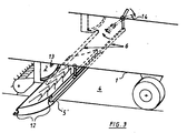
- FIG. 3 A further embodiment of the invention is shown schematically in FIG. 3.
- the cutting frame 5 is first pivoted downward by about 30 ° about the front circular sliding guide 12 by means of the pivot lever 14, so that the knives 3 no longer protrude into the conveying channel 2 and then laterally after releasing a locking device, not shown, z. B. pulled out on handles 9.
- the cutting frame 5 can be pulled out completely so that all knives 3 are accessible.
- a grinding device 11 can be fastened above the cutting frame 5 at a pivot point 13 on the side of the loading wagon 1, so that the cutting frame 5 can be pulled out step by step by a knife distance or, if necessary, turned out with a crank (not shown), one knife in each case is ground.
- the cutting frame 5 can form a component together with the bottom plate of the conveying channel 2, the drawer-like pulling out of the cutting frame 5 no longer having to be pivoted downwards, but only need to be shifted laterally, provided the knives 3 are each between two conveying rakes the conveyor are slidable.
- This design is particularly suitable for loader wagons with a few continuous conveyor rakes or for loader wagons with only one row of knives, since such one can also be moved transversely even with closely spaced conveyor rakes, possibly only in a certain rotational position of the conveyor device.
- z. B simpler U-profiles can be used.
Landscapes
- Life Sciences & Earth Sciences (AREA)
- Environmental Sciences (AREA)
- Harvester Elements (AREA)
- Disintegrating Or Milling (AREA)
Abstract
Description
Die Erfindung betrifft einen Ladewagen mit den Merkmalen des Oberbegriffs des Anspruchs 1.The invention relates to a loading wagon with the features of the preamble of claim 1.
Die Messer eines Ladewagens sind im Betrieb einer dauernden Belastung durch das zu schneidende Gut ausgesetzt und nützen sich im Laufe der Zeit an der Schneide ab. Um den zeitraubenden Ausbau der einzelnen Messer zum Nachschleifen zu vermeiden, wird in der EP-A-0044966 vorgeschlagen, die Messerreihe(n) mittels eines Rahmens in eine untere Lage außerhalb des Förderkanals zu verschwenken. Die Messer müssen dabei zwar nicht herausgenommen werden, jedoch muß hierbei die Bedienperson im beengten Raum zwischen abgeklappten Rahmen mit den Messern und der Unterseite des Laderaums mit dem Schleifgerät hantieren. Dadurch wird zudem ein exaktes Schleifen der Schneidkanten erschwert, da durch die gebückte Haltung der knieenden Bedienperson und dem Arbeiten in Vorlage eine genaue Führung des Schleifgerätes kaum möglich ist. Zudem ist für die Stromversorgung des Schleifgerätes nahezu immer ein Verlängerungskabel nötig, da das Stromkabel am meist verwendeten Winkelschleifer für die Verbindung zu der Steckdose in der Werkstatt zu kurz ist. Durch das Kabelgewirr ergeben sich zusätzliche Unfallgefahren.The knives of a loading wagon are exposed to a permanent load from the material to be cut during operation and will wear out on the cutting edge over time. In order to avoid the time-consuming removal of the individual knives for regrinding, it is proposed in EP-A-0044966 to pivot the row of knives into a lower position outside the conveying channel by means of a frame. The knives do not have to be removed, but the operator must handle the knives in the confined space between the folded frame and the knives and the underside of the loading space. This also makes it difficult to grind the cutting edges precisely, since the kneeling operator's stooped posture and working in front of him make it almost impossible to precisely guide the grinder. In addition, an extension cable is almost always required for the power supply to the grinder, since the power cable on the most commonly used angle grinder is too short for the connection to the socket in the workshop. The tangle of cables creates additional risk of accidents.
Desweiteren ist aus der DE-PS 33 23 116 eine Schleifvorrichtung bekannt, die an einer Querstange über die Breite des Förderkanals verschiebbar ist und in der Vertikalebene der Messer verschwenkbar ist, wobei durch dieFührung des Schleifgerätes ein exakter Schliff erreicht werden soll. Nachteilig ist hierbei jedoch, daß die Bedienperson weiterhin zum Nachschleifen unter den Ladewagen kriechen muß und in knieender, vornübergebeugter Haltung das Schleifgerät bedienen muß. Dies ist besonders bei nassem, schmutzigem Boden sehr unangenehm.Furthermore, from DE-PS 33 23 116 a grinding device is known which is displaceable on a cross bar across the width of the conveying channel and can be pivoted in the vertical plane of the knives, an exact grinding being achieved by the guidance of the grinding device. The disadvantage here, however, is that the operator must continue to crawl under the loading wagon for regrinding and must operate the grinder in a kneeling, bent-over position. This is very uncomfortable, especially on wet, dirty floors.
Der Erfindung liegt somit die Aufgabe zugrunde, diese Nachteile zu vermeiden und einen Ladewagen der genannten Art zu schaffen, bei dem das Schleifen der Messer bei geringem Zeitaufwand in einer ergonomisch günstigen Haltung der Bedienperson möglich ist.The invention is therefore based on the object of avoiding these disadvantages and of creating a loading wagon of the type mentioned, in which the grinding of the knives is possible with little expenditure of time in an ergonomically favorable position of the operator.
Diese Aufgabe wird erfindungsgemäß durch die kennzeichnenden Merkmale des Anspruchs 1 gelöst.This object is achieved by the characterizing features of claim 1.
Dadurch ist die Zugänglichkeit der Messer uneingeschränkt und die ergonomische Haltung der Bedienperson beim Nachschleifen optimal. Zudem ist der gesamte Schneidrahmen mit den Messern z. B. in eine Werkstatt fahrbar, so daß auch kleinere Reparaturen bequem erfolgen können. Ebenso ist in einer Werkstatt meist eine gute Beleuchtung vorhanden, so daß das Nachschleifen auch abends durchgeführt werden kann, während bisher das Nachschleifen, gerade in der Haupterntezeit, oft noch unter Taschenlampenbeleuchtung erfolgen mußte. Weiterhin sind in der Werkstatt sämtliche Werkzeuge in Griffnähe und die Stromversorgung auf kurzem Wege möglich, um z.B. ein stärker beschädigtes Messer auszurichten oder ggf. auszubauen.
Bei einer bevorzugten Ausführungsform des Schneidrahmens können die für eine sichere Auflage und Transport nötigen drei oder vier Räder am Schneidrahmen dauernd verbleiben, so daß der Ausbau des Schneidrahmens durch die Schnellverschlüsse in Sekunden erledigt werden kann. Diese Zeit wird durch die bequeme Arbeitshaltung und günstigen Arbeitsbedingungen mehrfach wieder hereingeholt. Weitere vorteilhafte Ausgestaltungen sind Gegenstand der Unteransprüche und der Zeichnungen.This means that the knives are fully accessible and the operator's ergonomic posture is optimal when regrinding. In addition, the entire cutting frame with the knives z. B. mobile in a workshop, so that even minor repairs can be done comfortably. Likewise, good lighting is usually available in a workshop, so that regrinding can also be carried out in the evening, whereas previously regrinding had to be carried out under flashlight lighting, especially in the main harvest time. Furthermore, all tools are within easy reach in the workshop and the power supply can be used in a short way, for example to align or, if necessary, remove a more damaged knife.
In a preferred embodiment of the cutting frame, the three or four wheels required for secure support and transport can remain permanently on the cutting frame, so that the removal of the cutting frame can be done in seconds by the quick-release fasteners. This time is brought back several times by the comfortable working posture and favorable working conditions. Further advantageous embodiments are the subject of the dependent claims and the drawings.
Ein Ausführungsbeispiel der Erfindung wird anhand der Zeichnungen nachfolgend näher beschrieben. Es zeigt:
- Fig. 1:
- eine schematische Seitenansicht eines Ladewagens mit eingebautem Schneidrahmen
- Fig. 2:
- den ausgebauten Schneidrahmen, der nach Lösen von Schnellverschlüssen seitlich unter dem Ladewagen herausgezogen ist.
- Fig. 3:
- eine perspektivische Ansicht des teilweise seitlich herausgezogenem Schneidrahmens.
- Fig. 1:
- a schematic side view of a loading wagon with built-in cutting frame
- Fig. 2:
- the removed cutting frame, which is pulled out laterally under the loading wagon after releasing quick-release fasteners.
- Fig. 3:
- a perspective view of the cutting frame partially pulled out laterally.
In Fig. 1 ist ein Ladewagen 1 teilweise dargestellt, bei dem das vom Boden aufgenommene Futtergut durch den Förderkanal 2 in den Laderaum gefördert wird. In den Förderkanal 2 ragen die Messer 3, die am Schneidrahmen 5 ggf. mittels nicht dargestellten Überlastsicherungen befestigt sind. Zwischen dem Förderkanal 2 und der Achse des Ladewagens 1 ergibt sich unterhalb dem Laderaum des Ladewagens 1 der Freiraum 4. Mit 6 sind die Abstützelemente bezeichnet, die gemäß Fig. 2 als Stützräder 7 oder gemäß Fig. 3 als Schiebeführung 12 ausgebildet sein können.In Fig. 1, a loading wagon 1 is partially shown, in which the feed material picked up from the ground is conveyed through the conveying
In Fig. 2 sind Schnellverschlüsse 8 dargestellt, die hier z. B. als Bolzen/Fanghaken-Verbindung ausgebildet sind. Nach dem Herausschwenken der Messer 3 aus dem Förderkanal 2 mittels des Schneidrahmens 5, wobei dann die Stützräder 7 auf dem Boden aufsetzen (vgl. strichliniert in Fig. 1) und dem Lösen der Schnellverschlüsse 8 kann der gesamte Schneidrahmen 5 auf einfache Weise seitlich unter dem Ladewagen 1 herausgezogen werden. Bei Bedarf kann der Schneidrahmen in die Hofwerkstatt weitertransportiert werden oder sogleich neben dem Ladewagen die Messer nachgeschliffen werden. In dieser Schleifstellung 5ʹ des Schneidrahmens 5 sind die Messer 3 von vorne her ohne Beengung durch den Ladewagen erreichbar, so daß die Bedienperson in ergonomisch günstiger Haltung die Messer 3 schleifen kann. Als zusätzliche Hilfe kann auch eine Führung 10 auf den Schneidrahmen 5 aufgesteckt werden, so daß der Anschliffwinkel der Messer konstant bleibt, da das anmontierte Schleifgerät 11 exakt geführt wird.In Fig. 2 quick-release fasteners 8 are shown, which here, for. B. are designed as a bolt / catch hook connection. After swiveling the
In Fig. 3 ist eine weitere Ausführungsform der Erfindung schematisch dargestellt. Hierbei werden die Abstützelemente für den relativ schweren Schneidrahmen 5 mit der Vielzahl von Messern 3 durch die Schiebeführungen 12 gebildet, an denen der Schneidrahmen 5 schubladenartig zur Seite herausgezogen werden kann. Hierzu wird zunächst der Schneidrahmen 5 um die vordere Rund-Schiebeführung 12 mittels des Schwenkhebels 14 um ca. 30° nach unten geschwenkt, so daß die Messer 3 nicht mehr in den Förderkanal 2 hineinragen und so dann nach Lösen einer nicht dargestellten Arretierung seitlich z. B. an Handgriffen 9 herausgezogen. Dabei kann der Schneidrahmen 5 vollkommen herausgezogen werden, so daß alle Messer 3 zugänglich sind. Ebenso kann über dem Schneidrahmen 5 an einem Anlenkpunkt 13 an der Seite des Ladewagens 1 ein Schleifgerät 11 befestigt werden, so daß der Schneidrahmen 5 schrittweise jeweils um einen Messerabstand herausgezogen oder ggf. mit einer nicht dargestellten Kurbel herausgedreht werden kann, wobei jeweils ein Messer 3 geschliffen wird.A further embodiment of the invention is shown schematically in FIG. 3. Here, the support elements for the relatively
Außerdem kann der Schneidrahmen 5 zusammen mit dem Bodenblech des Förderkanals 2 ein Bauteil bilden, wobei für das schubladenartige Herausziehen des Schneidrahmens 5 dieser nicht mehr erst nach unten verschwenkt werden braucht, sondern nur noch seitlich verschoben werden braucht, sofern die Messer 3 jeweils zwischen zwei Förderrechen der Fördervorrichtung querverschiebbar sind. Diese Ausbildung eignet sich besonders für Ladewagen mit wenigen durchgehenden Förderrechen oder für Ladewagen mit lediglich einer Messerreihe, da eine solche auch bei dicht aufeinanderfolgenden Förderrechen, ggf. nur in einer bestimmten Drehstellung der Fördervorrichtung quer verschiebbar sind. Durch diese Maßnahme können als Schiebeführungen 12 auch z. B. einfachere U-Profile eingesetzt werden.
Durch diese Ausbildung der Schneidrahmen kann neben der optimalen Zugänglichkeit der Messer zum Nachschleifen auch ein kompletter Austausch des gesamten Schneidrahmens leicht und schnell durchgeführt werden, wenn ein zweiter kompletter Schneidrahmen vorhanden ist. Dies wird insbesondere von Lohnunternehmen gewünscht, da in Erntespitzenzeiten kaum Zeit zum Nachschleifen bleibt und bei deren hohen Transportvolumen oft ein oder mehrere Wechsel bzw. Nachschleifen der Messer an einem Arbeitstag nötig ist.In addition, the
With this design of the cutting frame, in addition to the optimal accessibility of the knives for regrinding, a complete exchange of the entire cutting frame can also be carried out easily and quickly if a second complete cutting frame is present. This is particularly desirable by contractors, as there is hardly any time for regrinding during peak harvest times and, given their high transport volume, one or more knife changes or regrinding are often necessary on one working day.
Claims (10)
- Loading waggon with a conveying channel into which in operation position a number of knives (3) is projecting, and having at its rear at least one knife-supporting cutting frame (5) arranged in a free space (4) below the loading waggon, said cutting frame (5) extending over the width of the conveying channel and being displaceable to a grinding position, characterized in that the cutting frame (5) is formed laterally displaceable at supporting elements (6) and is movable from the free space (4) into a well accessible grinding position (5') beside the loading waggon (1).
- Loading waggon according to claim 1, characterized in that there are provided supporting wheels (7) as supporting elements (6), and the cutting frame (5) is releasable from the loading waggon (1) by quick couplers (8).
- Loading waggon according to claim 2, characterized in that the supporting wheels (7) are pluggable for the movement into the grinding position (5').
- Loading waggon according to claim 2, characterized in that the supporting wheels (7) are fixed to the cutting frame (5).
- Loading waggon according to claim 1, characterized in that the cutting frame (5) is provided with handles (9).
- Loading waggon according to claim 2, characterized in that at least one supporting wheel (7) is formed steerable.
- Loading waggon according to claim 2, characterized in that at the cutting frame (5) there is provided at least one guidance (10) extending transversely to the orientation of the knives and adapted to have attached thereto a grinding apparatus (11).
- Loading waggon according to claim 1, characterized in that the supporting elements (6) are formed by railings (12) extending over the width of the conveying channel (2) and on which the cutting frame (5) is displaceable in a drawer-like manner into the grinding position (5').
- Loading waggon according to claim 8, characterized in that a grinding apparatus (11) is mountable to an articulation point (13) at one side of the loading waggon (1) and is pivotable in the appropriate vertical plane of the individual knives (3).
- Loading waggon according to claim 8, characterized in that the radii of curvature of the cutting edges of the knives (3) correspond to the travelling path of the grinding apparatus (11) around the articulation point (13).
Priority Applications (1)
| Application Number | Priority Date | Filing Date | Title |
|---|---|---|---|
| AT88103038T ATE67064T1 (en) | 1987-04-03 | 1988-03-01 | LOADER WAGON. |
Applications Claiming Priority (2)
| Application Number | Priority Date | Filing Date | Title |
|---|---|---|---|
| DE3711355 | 1987-04-03 | ||
| DE3711355A DE3711355C1 (en) | 1987-04-03 | 1987-04-03 | Loading wagons |
Publications (2)
| Publication Number | Publication Date |
|---|---|
| EP0284792A1 EP0284792A1 (en) | 1988-10-05 |
| EP0284792B1 true EP0284792B1 (en) | 1991-09-11 |
Family
ID=6324853
Family Applications (1)
| Application Number | Title | Priority Date | Filing Date |
|---|---|---|---|
| EP88103038A Expired - Lifetime EP0284792B1 (en) | 1987-04-03 | 1988-03-01 | Self-loading forage box |
Country Status (3)
| Country | Link |
|---|---|
| EP (1) | EP0284792B1 (en) |
| AT (1) | ATE67064T1 (en) |
| DE (1) | DE3711355C1 (en) |
Families Citing this family (7)
| Publication number | Priority date | Publication date | Assignee | Title |
|---|---|---|---|---|
| DE9308656U1 (en) * | 1993-06-09 | 1993-08-12 | Alois Pöttinger Maschinenfabrik Ges.m.b.H., Grieskirchen | Harvester with cutting unit |
| DE102006036199B4 (en) * | 2006-08-03 | 2016-01-07 | Deere & Company | Conveyor assembly and press |
| DE102010050584A1 (en) * | 2010-11-05 | 2012-05-10 | Alois Pöttinger Maschinenfabrik Gmbh | harvester |
| DE102012109773A1 (en) * | 2012-05-03 | 2013-11-07 | Usines Claas France S.A.S. | Harvester with a cutting device |
| DE102012008721A1 (en) * | 2012-05-03 | 2013-11-07 | Usines Claas France S.A.S. | Harvester with a cutting device |
| NL2010354C2 (en) * | 2013-02-22 | 2014-08-25 | Forage Innovations Bv | Conveying arrangement with knives which can be pivoted vertically and shifted laterally. |
| EP4374682A1 (en) * | 2022-11-23 | 2024-05-29 | CNH Industrial Belgium N.V. | Harvesting machine |
Family Cites Families (4)
| Publication number | Priority date | Publication date | Assignee | Title |
|---|---|---|---|---|
| DE1928261U (en) * | 1965-09-01 | 1965-12-02 | Elise Tebbe Machinen Und Fahrz | AGRICULTURAL Z LOADER WAGON WITH CUTTING DEVICE. |
| DE1954212U (en) * | 1966-08-30 | 1967-01-26 | Steinkuhle Kg Friedr | AGRICULTURAL LOADER VEHICLE. |
| DE3028306C2 (en) * | 1980-07-25 | 1986-01-30 | ALOIS PöTTINGER MASCHINENFABRIK GMBH, GRIESKIRCHEN | Cutting unit for agricultural implements, in particular self-loading wagons |
| DE3323116C2 (en) * | 1983-06-27 | 1985-11-07 | Klöckner-Humboldt-Deutz AG Zweigniederlassung Fahr, 7702 Gottmadingen | Loader wagon with grinding device |
-
1987
- 1987-04-03 DE DE3711355A patent/DE3711355C1/en not_active Expired
-
1988
- 1988-03-01 AT AT88103038T patent/ATE67064T1/en not_active IP Right Cessation
- 1988-03-01 EP EP88103038A patent/EP0284792B1/en not_active Expired - Lifetime
Also Published As
| Publication number | Publication date |
|---|---|
| ATE67064T1 (en) | 1991-09-15 |
| EP0284792A1 (en) | 1988-10-05 |
| DE3711355C1 (en) | 1988-04-28 |
Similar Documents
| Publication | Publication Date | Title |
|---|---|---|
| DE1949978A1 (en) | Universal tractor | |
| EP0073360B1 (en) | Mowing machine | |
| DE3134389A1 (en) | MOWER | |
| DE2834197C2 (en) | Equipment carrier | |
| EP0284792B1 (en) | Self-loading forage box | |
| DE3028306C2 (en) | Cutting unit for agricultural implements, in particular self-loading wagons | |
| EP0066238B1 (en) | Harvesting machine for harvesting crops arranged in rows | |
| DE2412461C3 (en) | Forage harvester | |
| EP0204967B1 (en) | Loader with a grinding device | |
| DE1930687B2 (en) | UNLOADING DEVICE FOR A MOBILE TREE WORKING MACHINE | |
| DE8709233U1 (en) | Rotary haymaking machine | |
| DE69605466T2 (en) | Application device for a seed drill | |
| EP0105055B1 (en) | Lorry for receiving a harvesting device | |
| DE570506C (en) | Cotton harvester | |
| CH674441A5 (en) | ||
| DE1130644B (en) | Combine harvester with attached straw press | |
| DE69228637T2 (en) | Device for mowing standing grain | |
| DE202011100212U1 (en) | Trailers, in particular for the transport of wood | |
| AT390547B (en) | DEVICE FOR CUTTING OUT, RECORDING AND RELEASING FORAGE BLOCKS FROM FLAT SILOS | |
| DE4220776C1 (en) | Flat silo cutter and transfer unit attachable to rear of fodder truck - has U=shaped cutter raised and lowered hydraulically by parallelogram beams to move over rear of truck into end unloading position | |
| DE3625514C2 (en) | ||
| AT377412B (en) | CUTTING DEVICE FOR AGRICULTURAL EQUIPMENT, IN PARTICULAR SELF-LOADING TROLLEY | |
| AT346636B (en) | MOWER | |
| DE1205334B (en) | Pulled equipment, especially forage harvesters | |
| AT209619B (en) | Device for lateral displacement of the crop lying on the ground |
Legal Events
| Date | Code | Title | Description |
|---|---|---|---|
| PUAI | Public reference made under article 153(3) epc to a published international application that has entered the european phase |
Free format text: ORIGINAL CODE: 0009012 |
|
| AK | Designated contracting states |
Kind code of ref document: A1 Designated state(s): AT BE CH FR IT LI NL |
|
| 17P | Request for examination filed |
Effective date: 19881216 |
|
| 17Q | First examination report despatched |
Effective date: 19900627 |
|
| RAP1 | Party data changed (applicant data changed or rights of an application transferred) |
Owner name: KARL MENGELE & SOEHNE, MASCHINENFABRIKEN GMBH & CO |
|
| GRAA | (expected) grant |
Free format text: ORIGINAL CODE: 0009210 |
|
| AK | Designated contracting states |
Kind code of ref document: B1 Designated state(s): AT BE CH FR IT LI NL |
|
| PG25 | Lapsed in a contracting state [announced via postgrant information from national office to epo] |
Ref country code: IT Free format text: LAPSE BECAUSE OF FAILURE TO SUBMIT A TRANSLATION OF THE DESCRIPTION OR TO PAY THE FEE WITHIN THE PRE;WARNING: LAPSES OF ITALIAN PATENTS WITH EFFECTIVE DATE BEFORE 2007 MAY HAVE OCCURRED AT ANY TIME BEFORE 2007. THE CORRECT EFFECTIVE DATE MAY BE DIFFERENT FROM THE ONE RECORDED.SCRIBED TIME-LIMIT Effective date: 19910911 |
|
| REF | Corresponds to: |
Ref document number: 67064 Country of ref document: AT Date of ref document: 19910915 Kind code of ref document: T |
|
| EN | Fr: translation not filed | ||
| PG25 | Lapsed in a contracting state [announced via postgrant information from national office to epo] |
Ref country code: FR Effective date: 19920131 |
|
| PGFP | Annual fee paid to national office [announced via postgrant information from national office to epo] |
Ref country code: BE Payment date: 19920327 Year of fee payment: 5 |
|
| PGFP | Annual fee paid to national office [announced via postgrant information from national office to epo] |
Ref country code: CH Payment date: 19920331 Year of fee payment: 5 Ref country code: NL Payment date: 19920331 Year of fee payment: 5 |
|
| PGFP | Annual fee paid to national office [announced via postgrant information from national office to epo] |
Ref country code: AT Payment date: 19920428 Year of fee payment: 5 |
|
| PLBE | No opposition filed within time limit |
Free format text: ORIGINAL CODE: 0009261 |
|
| STAA | Information on the status of an ep patent application or granted ep patent |
Free format text: STATUS: NO OPPOSITION FILED WITHIN TIME LIMIT |
|
| 26N | No opposition filed | ||
| REG | Reference to a national code |
Ref country code: FR Ref legal event code: ST |
|
| PG25 | Lapsed in a contracting state [announced via postgrant information from national office to epo] |
Ref country code: AT Effective date: 19930301 |
|
| PG25 | Lapsed in a contracting state [announced via postgrant information from national office to epo] |
Ref country code: CH Effective date: 19930331 Ref country code: BE Effective date: 19930331 Ref country code: LI Effective date: 19930331 |
|
| BERE | Be: lapsed |
Owner name: KARL MENGELE & SOHNE MASCHINENFABRIKEN G.M.B.H. & Effective date: 19930331 |
|
| PG25 | Lapsed in a contracting state [announced via postgrant information from national office to epo] |
Ref country code: NL Effective date: 19931001 |
|
| NLV4 | Nl: lapsed or anulled due to non-payment of the annual fee | ||
| REG | Reference to a national code |
Ref country code: CH Ref legal event code: PL |