EP0284651B1 - Signalstern - Google Patents
Signalstern Download PDFInfo
- Publication number
- EP0284651B1 EP0284651B1 EP87113942A EP87113942A EP0284651B1 EP 0284651 B1 EP0284651 B1 EP 0284651B1 EP 87113942 A EP87113942 A EP 87113942A EP 87113942 A EP87113942 A EP 87113942A EP 0284651 B1 EP0284651 B1 EP 0284651B1
- Authority
- EP
- European Patent Office
- Prior art keywords
- lacquer
- flare
- parachute
- pressed
- flare according
- Prior art date
- Legal status (The legal status is an assumption and is not a legal conclusion. Google has not performed a legal analysis and makes no representation as to the accuracy of the status listed.)
- Expired - Lifetime
Links
- 239000000203 mixture Substances 0.000 claims abstract 5
- 239000004922 lacquer Substances 0.000 claims description 21
- 229910052751 metal Inorganic materials 0.000 claims description 7
- 239000002184 metal Substances 0.000 claims description 7
- VWDWKYIASSYTQR-UHFFFAOYSA-N sodium nitrate Chemical compound [Na+].[O-][N+]([O-])=O VWDWKYIASSYTQR-UHFFFAOYSA-N 0.000 claims description 6
- 229920003002 synthetic resin Polymers 0.000 claims description 6
- 239000000057 synthetic resin Substances 0.000 claims description 6
- 229910044991 metal oxide Inorganic materials 0.000 claims description 4
- 150000004706 metal oxides Chemical class 0.000 claims description 4
- 239000000725 suspension Substances 0.000 claims description 4
- 230000004888 barrier function Effects 0.000 claims description 3
- 239000008187 granular material Substances 0.000 claims description 3
- 239000000463 material Substances 0.000 claims description 3
- 229920000098 polyolefin Polymers 0.000 claims description 3
- 235000010344 sodium nitrate Nutrition 0.000 claims description 3
- 239000004317 sodium nitrate Substances 0.000 claims description 3
- 229910000861 Mg alloy Inorganic materials 0.000 claims description 2
- 229920000180 alkyd Polymers 0.000 claims description 2
- 229920001971 elastomer Polymers 0.000 claims description 2
- 239000003822 epoxy resin Substances 0.000 claims description 2
- 229920000647 polyepoxide Polymers 0.000 claims description 2
- 229920000728 polyester Polymers 0.000 claims description 2
- 229920002635 polyurethane Polymers 0.000 claims description 2
- 239000004814 polyurethane Substances 0.000 claims description 2
- 239000000020 Nitrocellulose Substances 0.000 claims 1
- 238000004873 anchoring Methods 0.000 claims 1
- 230000002401 inhibitory effect Effects 0.000 claims 1
- 229920001220 nitrocellulos Polymers 0.000 claims 1
- 150000003839 salts Chemical class 0.000 claims 1
- 238000010276 construction Methods 0.000 abstract 1
- 239000000126 substance Substances 0.000 description 5
- 229910052782 aluminium Inorganic materials 0.000 description 4
- XAGFODPZIPBFFR-UHFFFAOYSA-N aluminium Chemical compound [Al] XAGFODPZIPBFFR-UHFFFAOYSA-N 0.000 description 4
- 239000011248 coating agent Substances 0.000 description 4
- 238000000576 coating method Methods 0.000 description 4
- 238000002485 combustion reaction Methods 0.000 description 4
- 238000004519 manufacturing process Methods 0.000 description 4
- 239000003380 propellant Substances 0.000 description 4
- 239000002966 varnish Substances 0.000 description 4
- 229910052500 inorganic mineral Inorganic materials 0.000 description 3
- 239000011707 mineral Substances 0.000 description 3
- ZAMOUSCENKQFHK-UHFFFAOYSA-N Chlorine atom Chemical compound [Cl] ZAMOUSCENKQFHK-UHFFFAOYSA-N 0.000 description 2
- FYYHWMGAXLPEAU-UHFFFAOYSA-N Magnesium Chemical compound [Mg] FYYHWMGAXLPEAU-UHFFFAOYSA-N 0.000 description 2
- QVGXLLKOCUKJST-UHFFFAOYSA-N atomic oxygen Chemical compound [O] QVGXLLKOCUKJST-UHFFFAOYSA-N 0.000 description 2
- 239000011230 binding agent Substances 0.000 description 2
- 239000000460 chlorine Substances 0.000 description 2
- 229910052801 chlorine Inorganic materials 0.000 description 2
- 238000010304 firing Methods 0.000 description 2
- 239000011777 magnesium Substances 0.000 description 2
- 229910052749 magnesium Inorganic materials 0.000 description 2
- 239000001301 oxygen Substances 0.000 description 2
- 229910052760 oxygen Inorganic materials 0.000 description 2
- 239000000123 paper Substances 0.000 description 2
- 239000000049 pigment Substances 0.000 description 2
- 238000003825 pressing Methods 0.000 description 2
- 238000003860 storage Methods 0.000 description 2
- 239000004925 Acrylic resin Substances 0.000 description 1
- 239000004801 Chlorinated PVC Substances 0.000 description 1
- 229920003347 Microthene® Polymers 0.000 description 1
- 208000027418 Wounds and injury Diseases 0.000 description 1
- AZDRQVAHHNSJOQ-UHFFFAOYSA-N alumane Chemical group [AlH3] AZDRQVAHHNSJOQ-UHFFFAOYSA-N 0.000 description 1
- 230000015572 biosynthetic process Effects 0.000 description 1
- 238000005266 casting Methods 0.000 description 1
- 239000006103 coloring component Substances 0.000 description 1
- 230000006378 damage Effects 0.000 description 1
- 238000001514 detection method Methods 0.000 description 1
- 238000010790 dilution Methods 0.000 description 1
- 239000012895 dilution Substances 0.000 description 1
- 239000004744 fabric Substances 0.000 description 1
- 239000000446 fuel Substances 0.000 description 1
- 239000003365 glass fiber Substances 0.000 description 1
- 238000005469 granulation Methods 0.000 description 1
- 230000003179 granulation Effects 0.000 description 1
- 239000003112 inhibitor Substances 0.000 description 1
- 208000014674 injury Diseases 0.000 description 1
- 238000004898 kneading Methods 0.000 description 1
- 239000002655 kraft paper Substances 0.000 description 1
- 235000021388 linseed oil Nutrition 0.000 description 1
- 239000000944 linseed oil Substances 0.000 description 1
- 238000000034 method Methods 0.000 description 1
- 238000002156 mixing Methods 0.000 description 1
- 125000000449 nitro group Chemical group [O-][N+](*)=O 0.000 description 1
- 239000003921 oil Substances 0.000 description 1
- 235000019198 oils Nutrition 0.000 description 1
- SOQBVABWOPYFQZ-UHFFFAOYSA-N oxygen(2-);titanium(4+) Chemical class [O-2].[O-2].[Ti+4] SOQBVABWOPYFQZ-UHFFFAOYSA-N 0.000 description 1
- 239000003973 paint Substances 0.000 description 1
- 238000010422 painting Methods 0.000 description 1
- 239000004800 polyvinyl chloride Substances 0.000 description 1
- 239000000843 powder Substances 0.000 description 1
- 230000002028 premature Effects 0.000 description 1
- 238000005096 rolling process Methods 0.000 description 1
- 239000010703 silicon Substances 0.000 description 1
- 229910052814 silicon oxide Inorganic materials 0.000 description 1
- 239000002893 slag Substances 0.000 description 1
- OGIDPMRJRNCKJF-UHFFFAOYSA-N titanium oxide Inorganic materials [Ti]=O OGIDPMRJRNCKJF-UHFFFAOYSA-N 0.000 description 1
Images

Classifications
-
- F—MECHANICAL ENGINEERING; LIGHTING; HEATING; WEAPONS; BLASTING
- F42—AMMUNITION; BLASTING
- F42B—EXPLOSIVE CHARGES, e.g. FOR BLASTING, FIREWORKS, AMMUNITION
- F42B4/00—Fireworks, i.e. pyrotechnic devices for amusement, display, illumination or signal purposes
- F42B4/26—Flares; Torches
Definitions
- the present invention relates to signal stars according to the preamble of claim 1, as used in particular in parachute cartridges.
- signal stars are e.g. known from US-A-2 864 311.
- the signal stars can also be used with other signal cartridges.
- parachute cartridges or light cartridges are fired from civilian or military use from guns and burn z. B. from the so-called apron lighting on the parachute in a predetermined time.
- conventional ammunitions In order to make the burn-up sufficiently long or to prevent the signal star from burning too quickly, conventional ammunitions have the following structure.
- the actual star consists of a pressed light set, which is surrounded by a jacket in an aluminum sleeve and housed in a signal carrier.
- the star itself rests on an exhaust charge under which the deceleration rate and propellant rate are arranged.
- the latter can be surrounded by a tail unit and are located in a cartridge case with propellant charge before firing.
- a pyrotechnic light set has become known, which is brought out of a rocket housing and burns hanging from a parachute.
- the light set (signal star) is pressed and surrounded by a wrapping made of "kraft" paper or other suitable material (column 3, lines 66-68).
- the casing is placed in a mold and the set is pressed into it in several stages (column 6, lines 35 ff).
- a pressed pyrotechnic segmented set is also known which is provided with an inhibitor layer (column 5, lines 22-24).
- the housing of the set is divided, the part surrounding the light set remains as a casing on it when it burns.
- the object of the present invention is therefore to improve signal stars in such a way that hot residues are largely avoided at high light output and the burn-off image is enlarged.
- the production itself should be much easier.
- a signal for luminous stars consisting of a light set pressed at a pressure of about 500-1000 N / mm2 and surrounded by a sheath, in which, according to the invention, the outer sheath, when burned, consists of a synthetic resin lacquer layer with a thickness of about 0.1-0.15 mm, with the synthetic resin lacquer layer being applied to the pressed light set.
- the varnish coating provides an ideal seal of air humidity during storage.
- the paints should contain pigment, preferably in an amount of 20-80% by volume.
- Alkyd resin lacquer, chlorinated rubber lacquer, epoxy resin lacquer, acrylate resin lacquer, oil lacquer, nitro lacquer, polyester lacquer, polyurethane lacquer and the so-called combination lacquers, in which metal oxides can be incorporated, are primarily proposed.
- the present invention therefore proposes a different procedure for the production thereof, in order to achieve a reproducible predetermined burn-up on the one hand and on the other hand to improve its handling for the coating.
- the signal stars according to the invention consist of a compressed granulate.
- the latter is obtained in a simple manner by mixing and kneading the set with a binder. After subsequent granulation, pressable products are obtained.
- the pressure must be significantly higher than conventional and 500-1000 N / mm2 (with usual dimensions about 20 to 40 tons).
- the signal stars produced in this way are extremely stable and free of cracks. Their combustion behavior is homogeneous, they are particularly suitable for attaching the casing in the manner described above.
- An extension of the burning time can also be achieved in a simple manner by adding inert mineral substances, such as in particular metal oxides, as moderators to the light set. Silicon and titanium oxides have proven particularly suitable for this.
- the mineral substances can be added in amounts of 3-6% by weight, an increase in 6% mineral material resulting in an increase in the burning time of approximately 30%.
- the light sets according to the invention are used in parachute cartridges. This causes the parachute lines to burn in about 4% of the cases.
- a barrier layer of non-combustible oxides preferably of sodium nitrate, in the area of the suspension of the screen.
- suspensions and the barrier layer can be incorporated during the pressing or casting process.
- An effective additional protection of the parachute lines is further achieved according to the invention in that metal threads or glass fiber fabric is spun into the parachute lines or that these consist entirely of them.
- a so-called stocko cap is inserted into the parachute before it is pressed, through which a split pin is guided and spread.
- a metal perforated disc between the stock cap and the cotter pin, on which the entire set is filled and pressed. After removal from the mold, the perforated disc forms the star closure towards the parachute.
- the light set has the following recipe: Sodium nitrate + 1% linseed oil 37% by weight Polyolefin 3% by weight magnesium 60% by weight
- the polyolefin is e.g. B. a U.S.I. Chemicals manufactured and sold under the name Microthene.
- This light set was made with a binder from polychlorobutadiene 11.5% by weight and a dilution 6.6% by weight mixed, where as polychlorobutadiene z.
- B. a product known under the trade name "Macroplast" can be used.
- Fig. 1 shows the star according to the invention.
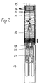
- Fig. 2 shows the structure of a parachute cartridge manufactured according to the invention.
- the star consists of a set 1 pressed from granulate as described above, as well as the intermediate set 2 and the firing 3. It is covered at the bottom with an aluminum ring 4, which can also be pressed.
- the star On the head side, the star has the perforated disk 5 made of Al Cu Mg alloy, through which the cotter pin 6 extends. Below the perforated disc 5, the stock cap 7 is held by the split pin 6.
- the perforated disc 5 is covered with a cardboard disc 8.
- the signal carrier is connected by bends to a tail unit 18, the ejection charge 19 for the star being accommodated in the bends.
- a deceleration charge 20 and a propellant charge 21 are located below the exhaust charge 19.
- the tail unit itself is located in a cartridge case (not shown) with propellant charge and primer prior to completion.
Landscapes
- Engineering & Computer Science (AREA)
- General Engineering & Computer Science (AREA)
- Luminescent Compositions (AREA)
- Acyclic And Carbocyclic Compounds In Medicinal Compositions (AREA)
- Length Measuring Devices By Optical Means (AREA)
- Paints Or Removers (AREA)
- Toys (AREA)
Description
- Die vorliegende Erfindung betrifft Signalsterne gemäß dem Oberbegriff des Anspruchs 1, wie sie insbesondere in Fallschirmpatronen verwendet werden. Solche Signalsterne sind z.B. aus der US-A-2 864 311 bekannt.
- Die Signalsterne können aber auch bei anderen Signalpatronen eingesetzt werden.
- Derartige Fallschirmpatronen oder Leuchtpatronen werden bei zivilem oder militärischem Einsatz aus Schußapparaten abgefeuert und brennen z. B. zur sogenannten Vorfeldbeleuchtung am Fallschirm hängend in vorgegebener Zeit ab. Um den Abbrand ausreichend lang zu gestalten bzw. um ein zu schnelles Durchbrennen des Signalsterns zu verhindern, weisen herkömmliche Munitionen folgenden Aufbau auf.
- Der eigentliche Stern besteht aus einem gepreßten Leuchtsatz, der von einem Mantel umgeben in einer Aluminiumhülse und in einem Signalträger untergebracht ist. Der Stern selbst ruht dabei auf einer Ausstoßladung, unter der der Verzögerungssatz und Treibsatz angeordnet sind. Letztere können von einem Leitwerk umgeben sein und befinden sich vor dem Abschuß in einer Patronenhülse mit Treibladung.
- Aus der US-A 2 442 528 ist ein pyrotechnischer Leuchtsatz bekannt geworden, der aus einem Raketengehäuse ausgebracht wird und an einem Fallschirm hängend abbrennt. Der Leuchtsatz (Signalstern) ist gepreßt und von einer Umhüllung aus "Kraft" Papier oder sonstigem geeignetem Material umgeben (Sp. 3, Z. 66-68). Zur Herstellung wird die Umhüllung in eine Form gegeben und der Satz in mehreren Stufen in diese hineingepreßt (Sp. 6, Z. 35 ff).
- Aus der US-A 3 749 019 ist weiterhin ein gepreßter pyrotechnischer segmentierter Satz bekannt, der mit einer Inhibitorschicht versehen ist (Sp. 5, Z. 22-24). Das Gehäuse des Satzes ist geteilt, der den Leuchtsatz umgebende Teil verbleibt beim Abbrand als Ummantelung an diesem.
- Die erwähnte Ummantelung aus Papier, Aluminium oder PVC dämpft die Abbrandgeschwindigkeit des Sterns.
- Nachteilig sind dabei u. a. ein relativ hoher durch die Ummantelung bedingter Leuchtstärkeverlust und gleichzeitig ein eng kegelförmiges Abbrandbild, wodurch aus ungünstigen Winkeln ein Erkennen erschwert wird. Zudem ist der Abbrand nicht rückstandsfrei, d. h. heiße Schlacke- oder Metallteile können zu Boden fallen und zu Verletzungen oder Bränden führen. Das stufenweise Verpressen in eine von einem Werkzeug gehaltene Hülle ist aufwendig.
- Die vorliegende Erfindung hat sich daher die Aufgabe gestellt, Signalsterne derart zu verbessern, daß bei hoher Lichtleistung das Herabfallen heißer Rückstände weitgehend vermieden und das Abbrandbild vergrößert wird. Die Herstellung selbst soll wesentlich einfacher sein.
- Die Lösung dieser Aufgabe gelingt gemäß Anspruch 1 mit einem Signal für Leuchtsterne, bestehend aus einem bei Drucken von etwa 500-1000 N/mm² gepreßten, von einer Umhüllung umgebenen Leuchtsatz, bei dem erfindungsgemäß die beim Abbrennen äußere Umhüllung aus einer Kunstharzlackschicht in einer Stärke von etwa 0,1-0,15 mm besteht, wobei die Kunstharzlackschicht auf den gepreßten Leuchtsatz aufgetragen ist.
- Überraschenderweise wurden für die erfindungsgemäßen Signalsterne Lichtausbeuten von 100.000 cd und darüber gemessen, wobei die Abbrandzeiten nicht verkürzt sind, der Abbrand ist außerdem weitgehend rückstandsfrei, herabfallende heiße Teile konnten nicht beobachtet werden, ein Durchschlagen der Flamme bzw. ein vorschnelles Verbrennen trat nicht auf.
- Der Lacküberzug ergibt einen idealen Abschluß von Luftfeuchtigkeit bei der Lagerung.
- Bei der Verwendung von Kunstharzlack haben sich Schichtdicken von etwa 0,1 bis 0,15 besonders gut bewährt, wobei es auch auf die Pigmenthaltigkeit ankommt, d. h. die Lacke sollen pigmenthaltig sein, vorzugsweise in Menge von 20-80 Vol % . Vorgeschlagen werden vornehmlich Alkydharzlack, Chlorkautschuklack, Epoxidharzlack, Acrylatharzlack, Öllack, Nitrolack, Polyesterlack, Polyurethanlack sowie die sogenannten Kombinationslacke, in die Metalloxide eingebunden sein können.
- Vorzuziehen ist die Verwendung eines pigmenthaltigen farbigen Lackes, da so gleichzeitig die Leuchtfarbe des Sternes gekennzeichnet werden kann.
- Herkömmliche Signalsterne werden aus dem Satz unter Drücken von üblicherweise 3000 bar gepreßt. Dabei entstehen häufig Falten in der Aluminiumhülle, die zur Rissbildung im Satz führen, d. h. dieser Signalstern würde nach dem Entfernen der Aluminiumhülle auseinanderfallen.
- Diese Risse verursachen beim Abbrand ein Splittern und führen außerdem zu Brennzeitverkürzungen.
- Die vorliegende Erfindung schlägt daher eine andere Vorgehensweise zu deren Herstellung vor, um einmal einen reproduzierbaren vorgegebenen Abbrand zu erzielen und zum anderen ihre Handhabbarkeit für die Lackierung zu verbessern.
- Die erfindungsgemäßen Signalsterne bestehen hierzu aus einem verpreßten Granulat. Letzteres wird in einfacher Weise dadurch erhalten, daß der Satz mit einem Bindemittel vermischt und geknetet wird. Nach anschließendem Granulieren erhält man preßfähige Produkte. Der Preßdruck muß dabei wesentlich höher sein als herkömmlich und 500-1000 N/mm² (bei üblichen Abmessungen etwa 20 bis 40 to) betragen.
- Die so hergestellten Signalsterne sind ausgesprochen stabil und frei von Rissen. Ihr Abbrandverhalten ist homogen, sie eignen sich in besonderer Weise zur Anbringung der Ummantelung in der oben beschriebenen Weise.
- Herkömmliche Sätze bestehen z. B. aus einem Sauerstoffträger, der gleichzeitig Farbgebungskomponente sein kann, einem Brennstoff (Metallpulver, wie Magnesium) und einem farbvertiefenden Abbrandmoderator. Dieser Abbrandmoderator ist eine stark Chlor-haltige Substanz, wie z. B. nachchloriertes PVC und wird in Mengen von ca. 10 % zugefügt. Überraschenderweise hat sich im Zusammenhang mit der vorliegenden Erfindung herausgestellt, daß die Leuchtkraft eines Signalsternes in Abwesenheit von Chlor-abgebenden Substanzen verbessert werden kann, wenn dem Satz anstelle der herkömmlichen Moderatoren Polyolefin in Mengen von lediglich ca. 3 Gew.-% zugegeben werden. Die Helligkeit steigert sich dabei um mindestens 10 % ohne Beeinträchtigung der Moderation.
- Eine Verlängerung der Brenndauer läßt sich in einfacher Weise auch dadurch erreichen, daß dem Leuchtsatz inerte mineralische Stoffe, wie insbesondere Metalloxide als Moderatoren zugegeben werden. Insbesondere haben sich hierfür Silicium und Titanoxide bewährt.
- Die mineralischen Stoffe können in Mengen von 3-6 Gew.-% zugegeben werden, wobei eine Zunahme an 6 % mineralischen Materials eine Brenndauerverlängerung von etwa 30 % mit sich bringt.
- Insbesondere werden die erfindungsgemäßen Leuchtsätze in Fallschirmpatronen verwendet. Dabei kommt es in etwa 4 % der Fälle zu einem Brennen der Fallschirmleinen. Um die Leinen des Schirmes zu schützen, wird vorgeschlagen, im Bereich der Aufhängung des Schirmes eine Sperrschicht aus nicht brennbaren Oxiden, vorzugsweise aus Natriumnitrat anzuordnen.
- In besonders vorteilhafter Weise können die Aufhängungen und die Sperrschicht beim Preß- oder Gießvorgang mit eingearbeitet werden.
- Ein wirksamer zusätzlicher Schutz der Fallschirmleinen wird weiterhin erfindungsgemäß dadurch erreicht, daß in die Fallschirmleinen Metallfäden oder Glasfasergewebe eingesponnen wird oder daß diese gänzlich daraus bestehen.
- Für die Befestigung des Fallschirmes wird vor dem Verpressen des Satzes eine sog. Stockokappe in diesen eingelegt, durch die ein Splint geführt und aufgespreizt ist. Zwischen der Stockokappe und der Splintöse befindet sich dabei eine Lochscheibe aus Metall, auf die der gesamte Satz gefüllt und gepreßt wird. Nach dem Entformen bildet die Lochscheibe den Sternabschluß nach oben zum Fallschirm hin.
- Diese Art der Befestigung ist erheblich weniger aufwendig, als die herkömmliche, bei der die Befestigung durch Einrollen des oberen Randes, z. B. der Ummantelung, auf die Abdeckscheibe vorgenommen werden muß.
- Im nachstehenden Ausführungsbeispiel wird die Herstellung eines mantellosen Signalsternes der Farbe gelb beschrieben.
- Der Leuchtsatz hat folgende Rezeptur:
Natriumnitrat + 1 % Leinöl 37 Gew.-% Polyolefin 3 Gew.-% Magnesium 60 Gew.-% - Bei dem Polyolefin handelt es sich z. B. um ein von der Firma U.S.I. Chemicals hergestelltes und unter der Bezeichnung Microthene vertriebenes Produkt.
- Dieser Leuchtsatz wurde mit einem Bindemittel bestehend
aus Polychlorbutadien 11,5 Gew.-% und einer Verdünnung 6,6 Gew.-%
vermischt, wobei als Polychlorbutadien z. B. ein unter dem Handelsnamen "Macroplast" bekanntes Produkt eingesetzt werden kann. - Anhand der beiliegenden Figuren wird die vorliegende Erfindung näher erläutert.
- Fig. 1 zeigt den erfindungsgemäßen Stern.
- Fig. 2 zeigt den Aufbau einer erfindungsgemäß hergestellten Fallschirmpatrone.
- Der Stern besteht aus einem aus Granulat wie oben beschrieben gepreßten Satz 1, sowie dem Zwischensatz 2 und der Anfeuerung 3. Er ist nach unten mit einem Aluminiumring 4 abgedeckt, der mitverpreßt sein kann. Kopfseitig weist der Stern die Lochscheibe 5 aus Al Cu Mg-Legierung auf, die vom Splint 6 durchgriffen ist. Unterhalb der Lochscheibe 5 ist die Stockokappe 7 vom gespreizten Splint 6 gehalten. Die Lochscheibe 5 ist mit einer Pappscheibe 8 abgedeckt.
- An der Öse 9 des Splints 6 befindet sich eine mit Befestigungsringen 10, 11 versehene Kette 12 zur Anbringung eines Fallschirmes.
- Mit 22 ist ein Lacküberzug einer Stärke von ca. 0,1 mm bezeichnet, der um den gepreßten Satz durch Lackierung gegeben wurde. Diese Umhüllung schließt Sauerstoffzutritt bei der Verbrennung ebenso wie Feuchtigkeitszutritt bei der Lagerung aus.
- In dieser Figur ist der gesamte Aufbau einer Fallschirmpatrone beispielhaft gezeigt.
- In dem Signalträger ist der Stern aus Fig. 1 angeordnet, über den der Fallschirm 14 gepackt ist. Auf dem Fallschirm 14 ruhen von einem Stopfen 15 gehalten Bleischeiben 16, die vom Schirm durch Scheiben 17 getrennt sind. Der Signalträger ist durch Abkantungen mit einem Leitwerk 18 verbunden, wobei in den Abkantungen die Ausstoßladung 19 für den Stern untergebracht ist. Unterhalb der Ausstoßladung 19 befinden sich ein Verzögerungssatz 20 und ein Treibsatz 21.
- Das Leitwerk selbst befindet sich vor dem Abschluß in einer nicht dargestellten Patronenhülse mit Treibladung und Zündhütchen.
Claims (8)
- Signalstern für Leuchtsignale, bestehend aus einem mit einer Umhüllung (22) umgebenen Leuchtsatz (1), dadurch gekennzeichnet, daß der Leuchtsatz aus einem bei Drücken von etwa 500 - 1.000 N/mm² verpreßten Granulat besteht und auf diesen eine dünne Kunstharzlackschicht in einer Stärke von etwa 0,1 - 0,15 mm als Umhüllung aufgetragen ist.
- Signalstern nach Anspruch 1, dadurch gekennzeichnet, daß der Kunstharzlack Metalloxide enthält.
- Signalstern nach Anspruch 1 oder 2, dadurch gekennzeichnet, daß als Kunstharzlack ein Alkydharzlack, ein Chlorkautschuklack, ein Epoxidharzlack, ein Nitrolack, ein Polyesterlack, ein Polyurethanlack oder ein Kombinationslack eingesetzt ist.
- Signalstern nach mindestens einem der Ansprüche 1 bis 3, dadurch gekennzeichnet, daß er als Abbrandmoderator Polyolefin und/oder Metalloxide oder andere feuerhemmende Oxide in Mengen von etwa 3 - 6 Gew.-% enthält.
- Signalstern nach mindestens einem der Ansprüche 1 bis 4, dadurch gekennzeichnet, daß man eine Verankerung für einen Fallschirm, bestehend aus einer Stockokappe und einem Splint mitverpreßt ist, wobei zwischen Splintöse und Sternoberfläche eine Lochscheibe aus Metall eingelegt ist.
- Signalstern nach Anspruch 5, dadurch gekennzeichnet, daß die Metallscheibe aus einer Al Cu Mg-legierung besteht.
- Signalstern nach mindestens einem der Ansprüche 1 bis 6, dadurch gekennzeichnet, daß er am Aufhängungsbereich des Fallschirmes eine Sperrschicht aus nicht brennbaren Salzen, wie vorzugsweise Natriumnitrat aufweist und/oder einem Metall oder flammhemmendem Material besteht.
- Signalstern nach mindestens einem der Ansprüche 5 - 7, dadurch gekennzeichnet, daß die Aufhängung für den Fallschirm mit verpreßt ist.
Priority Applications (1)
| Application Number | Priority Date | Filing Date | Title |
|---|---|---|---|
| AT87113942T ATE102340T1 (de) | 1987-04-03 | 1987-09-24 | Signalstern. |
Applications Claiming Priority (2)
| Application Number | Priority Date | Filing Date | Title |
|---|---|---|---|
| DE19873711285 DE3711285A1 (de) | 1986-09-11 | 1987-04-03 | Signalstern |
| DE3711285 | 1987-04-03 |
Publications (2)
| Publication Number | Publication Date |
|---|---|
| EP0284651A1 EP0284651A1 (de) | 1988-10-05 |
| EP0284651B1 true EP0284651B1 (de) | 1994-03-02 |
Family
ID=6324801
Family Applications (1)
| Application Number | Title | Priority Date | Filing Date |
|---|---|---|---|
| EP87113942A Expired - Lifetime EP0284651B1 (de) | 1987-04-03 | 1987-09-24 | Signalstern |
Country Status (4)
| Country | Link |
|---|---|
| EP (1) | EP0284651B1 (de) |
| AT (1) | ATE102340T1 (de) |
| DE (1) | DE3789225D1 (de) |
| ES (1) | ES2050656T3 (de) |
Families Citing this family (1)
| Publication number | Priority date | Publication date | Assignee | Title |
|---|---|---|---|---|
| DE102007015248A1 (de) | 2007-03-27 | 2008-10-02 | Chemring Defence Germany Gmbh | Fallschirmrakete, insbesondere Fallschirmsignalrakete und/oder Fallschirmleuchtrakete, und Verfahren zur Herstellung derselben |
Citations (2)
| Publication number | Priority date | Publication date | Assignee | Title |
|---|---|---|---|---|
| US2864311A (en) * | 1953-12-07 | 1958-12-16 | Unexcelled Chemical Corp | Flares |
| DE2226715A1 (de) * | 1971-06-21 | 1972-12-28 | Aktiebolaget Bofors, Bofors (Schweden) | Vorrichtung zur Elimination der Einwirkung von Temperaturvariationen auf die Befestigung einer Hülle in einem pyrotechnischen Leuchtkörper |
Family Cites Families (9)
| Publication number | Priority date | Publication date | Assignee | Title |
|---|---|---|---|---|
| FR650094A (fr) * | 1927-08-06 | 1929-01-04 | France Etat | Procédé destiné à augmenter le pouvoir d'émission des artifices producteurs de lumière, de gaz ou de fumée sans augmenter l'encombrement de ces artifices avant fonctionnement |
| US2442528A (en) * | 1943-11-20 | 1948-06-01 | Aerial Products Inc | Rocket device |
| US3068756A (en) * | 1958-12-10 | 1962-12-18 | Schermuly Pistol Rocket App | Dischargers for pyrotechnic devices |
| FR1274839A (fr) * | 1959-11-25 | 1961-10-27 | Gotex Ab | Dispositif de fusée |
| FR1277444A (fr) * | 1960-10-22 | 1961-12-01 | Hotchkiss Brandt | Roquette fumigène perfectionnée |
| US3593664A (en) * | 1968-12-26 | 1971-07-20 | Thiokol Chemical Corp | Aerial flare and parachute deployment means therefor |
| US3736206A (en) * | 1969-02-10 | 1973-05-29 | Thiokol Chemical Corp | Method for making a pyrotechnic device |
| US3749019A (en) * | 1971-09-08 | 1973-07-31 | E Hancock | Rocket-powered signaling device |
| US3750574A (en) * | 1972-02-28 | 1973-08-07 | Us Navy | Illuminating round having dual range capability |
-
1987
- 1987-09-24 ES ES87113942T patent/ES2050656T3/es not_active Expired - Lifetime
- 1987-09-24 EP EP87113942A patent/EP0284651B1/de not_active Expired - Lifetime
- 1987-09-24 AT AT87113942T patent/ATE102340T1/de not_active IP Right Cessation
- 1987-09-24 DE DE87113942T patent/DE3789225D1/de not_active Expired - Fee Related
Patent Citations (2)
| Publication number | Priority date | Publication date | Assignee | Title |
|---|---|---|---|---|
| US2864311A (en) * | 1953-12-07 | 1958-12-16 | Unexcelled Chemical Corp | Flares |
| DE2226715A1 (de) * | 1971-06-21 | 1972-12-28 | Aktiebolaget Bofors, Bofors (Schweden) | Vorrichtung zur Elimination der Einwirkung von Temperaturvariationen auf die Befestigung einer Hülle in einem pyrotechnischen Leuchtkörper |
Also Published As
| Publication number | Publication date |
|---|---|
| ATE102340T1 (de) | 1994-03-15 |
| EP0284651A1 (de) | 1988-10-05 |
| ES2050656T3 (es) | 1994-06-01 |
| DE3789225D1 (de) | 1994-04-07 |
Similar Documents
| Publication | Publication Date | Title |
|---|---|---|
| DE3515166C2 (de) | ||
| DE4244682B4 (de) | Hochintensive pyrotechnische Infrarot-Leuchtdrohne | |
| EP0664876B1 (de) | Verfahren zur scheinzielerzeugung | |
| DE3616004A1 (de) | Zuendmittel-zusammensetzung | |
| EP1173394B9 (de) | Pyrotechnische wirkmasse zur erzeugung eines im infraroten stark emissiven und im visuellen undurchdringlichen aerosols | |
| DE3326884A1 (de) | Verfahren zum verdecken sichtbarer und infraroter strahlung und nebelmunition zur durchfuehrung dieses verfahrens | |
| DE2819863C2 (de) | ||
| DE3238455A1 (de) | Nebelwurfkoerper | |
| DE2552950A1 (de) | Brandmunition | |
| CH674742A5 (de) | ||
| EP0284651A1 (de) | Signalstern | |
| DE3841690A1 (de) | Anzuendmischung | |
| EP0106334A2 (de) | Pyrotechnische Nebelsätze | |
| DE19602422C1 (de) | Munitionshülle aus Faserverbundmaterial | |
| DE19846511C2 (de) | Feuerwerkskörper mit nicht explosionsgefährlicher Effektfüllung | |
| DE2530206A1 (de) | Splitterbrandsatz | |
| EP0455980B1 (de) | Seemarkierer für Notanflugverfahren von Bordflugzeugen von Schiffen | |
| DE3711285A1 (de) | Signalstern | |
| DE2700170C3 (de) | Verfahren zur Verbesserung der Lagersicherheit von Braunkohlenstaub | |
| DE69310238T2 (de) | Verfahren und Vorrichtung zum Unschädlichmachen einer Bedrohung durch Freigabe eines Neutralisationsmittels | |
| DE2415847C1 (de) | Farbiger Leuchtspursatz für kleine Kalibermunition | |
| EP2770294B1 (de) | Sprengstoffwirkmasse für eine Gefechtsmunition | |
| DE4134859C2 (de) | ||
| DE4302476C2 (de) | Zündempfindliche elektrische Zündsätze mit schwachem detonativem Ausgang, Verfahren zu deren Herstellung, sowie deren Verwendung | |
| DE2808394A1 (de) | Anstechempfindliches zuendstoffgemisch, verfahren zu dessen herstellung und verwendung fuer einen detonator |
Legal Events
| Date | Code | Title | Description |
|---|---|---|---|
| PUAI | Public reference made under article 153(3) epc to a published international application that has entered the european phase |
Free format text: ORIGINAL CODE: 0009012 |
|
| AK | Designated contracting states |
Kind code of ref document: A1 Designated state(s): AT BE CH DE ES FR GB GR IT LI LU NL SE |
|
| 17P | Request for examination filed |
Effective date: 19880920 |
|
| 17Q | First examination report despatched |
Effective date: 19890523 |
|
| RAP1 | Party data changed (applicant data changed or rights of an application transferred) |
Owner name: PIEPENBROCK PYROTECHNIK GMBH |
|
| GRAA | (expected) grant |
Free format text: ORIGINAL CODE: 0009210 |
|
| AK | Designated contracting states |
Kind code of ref document: B1 Designated state(s): AT BE CH DE ES FR GB GR IT LI LU NL SE |
|
| REF | Corresponds to: |
Ref document number: 102340 Country of ref document: AT Date of ref document: 19940315 Kind code of ref document: T |
|
| ITF | It: translation for a ep patent filed | ||
| REF | Corresponds to: |
Ref document number: 3789225 Country of ref document: DE Date of ref document: 19940407 |
|
| GBT | Gb: translation of ep patent filed (gb section 77(6)(a)/1977) |
Effective date: 19940504 |
|
| REG | Reference to a national code |
Ref country code: ES Ref legal event code: FG2A Ref document number: 2050656 Country of ref document: ES Kind code of ref document: T3 |
|
| REG | Reference to a national code |
Ref country code: GR Ref legal event code: FG4A Free format text: 3011483 |
|
| ET | Fr: translation filed | ||
| PLBE | No opposition filed within time limit |
Free format text: ORIGINAL CODE: 0009261 |
|
| STAA | Information on the status of an ep patent application or granted ep patent |
Free format text: STATUS: NO OPPOSITION FILED WITHIN TIME LIMIT |
|
| EAL | Se: european patent in force in sweden |
Ref document number: 87113942.4 |
|
| 26N | No opposition filed | ||
| PGFP | Annual fee paid to national office [announced via postgrant information from national office to epo] |
Ref country code: FR Payment date: 19960617 Year of fee payment: 10 |
|
| PGFP | Annual fee paid to national office [announced via postgrant information from national office to epo] |
Ref country code: GR Payment date: 19960628 Year of fee payment: 10 |
|
| PGFP | Annual fee paid to national office [announced via postgrant information from national office to epo] |
Ref country code: GB Payment date: 19960905 Year of fee payment: 10 |
|
| PGFP | Annual fee paid to national office [announced via postgrant information from national office to epo] |
Ref country code: SE Payment date: 19960919 Year of fee payment: 10 Ref country code: AT Payment date: 19960919 Year of fee payment: 10 |
|
| PGFP | Annual fee paid to national office [announced via postgrant information from national office to epo] |
Ref country code: BE Payment date: 19960920 Year of fee payment: 10 |
|
| PGFP | Annual fee paid to national office [announced via postgrant information from national office to epo] |
Ref country code: CH Payment date: 19960923 Year of fee payment: 10 |
|
| PGFP | Annual fee paid to national office [announced via postgrant information from national office to epo] |
Ref country code: ES Payment date: 19960927 Year of fee payment: 10 |
|
| PGFP | Annual fee paid to national office [announced via postgrant information from national office to epo] |
Ref country code: NL Payment date: 19960930 Year of fee payment: 10 |
|
| PGFP | Annual fee paid to national office [announced via postgrant information from national office to epo] |
Ref country code: LU Payment date: 19961001 Year of fee payment: 10 |
|
| PGFP | Annual fee paid to national office [announced via postgrant information from national office to epo] |
Ref country code: DE Payment date: 19961121 Year of fee payment: 10 |
|
| PG25 | Lapsed in a contracting state [announced via postgrant information from national office to epo] |
Ref country code: LU Free format text: LAPSE BECAUSE OF NON-PAYMENT OF DUE FEES Effective date: 19970924 Ref country code: GB Free format text: LAPSE BECAUSE OF NON-PAYMENT OF DUE FEES Effective date: 19970924 Ref country code: AT Free format text: LAPSE BECAUSE OF NON-PAYMENT OF DUE FEES Effective date: 19970924 |
|
| PG25 | Lapsed in a contracting state [announced via postgrant information from national office to epo] |
Ref country code: SE Free format text: LAPSE BECAUSE OF NON-PAYMENT OF DUE FEES Effective date: 19970925 Ref country code: ES Free format text: LAPSE BECAUSE OF EXPIRATION OF PROTECTION Effective date: 19970925 |
|
| PG25 | Lapsed in a contracting state [announced via postgrant information from national office to epo] |
Ref country code: LI Free format text: LAPSE BECAUSE OF NON-PAYMENT OF DUE FEES Effective date: 19970930 Ref country code: GR Free format text: LAPSE BECAUSE OF NON-PAYMENT OF DUE FEES Effective date: 19970930 Ref country code: FR Free format text: THE PATENT HAS BEEN ANNULLED BY A DECISION OF A NATIONAL AUTHORITY Effective date: 19970930 Ref country code: CH Free format text: LAPSE BECAUSE OF NON-PAYMENT OF DUE FEES Effective date: 19970930 Ref country code: BE Free format text: LAPSE BECAUSE OF NON-PAYMENT OF DUE FEES Effective date: 19970930 |
|
| BERE | Be: lapsed |
Owner name: PIEPENBROCK PYROTECHNIK G.M.B.H. Effective date: 19970930 |
|
| PG25 | Lapsed in a contracting state [announced via postgrant information from national office to epo] |
Ref country code: NL Free format text: LAPSE BECAUSE OF NON-PAYMENT OF DUE FEES Effective date: 19980401 |
|
| GBPC | Gb: european patent ceased through non-payment of renewal fee |
Effective date: 19970924 |
|
| REG | Reference to a national code |
Ref country code: CH Ref legal event code: PL |
|
| NLV4 | Nl: lapsed or anulled due to non-payment of the annual fee |
Effective date: 19980401 |
|
| PG25 | Lapsed in a contracting state [announced via postgrant information from national office to epo] |
Ref country code: DE Free format text: LAPSE BECAUSE OF NON-PAYMENT OF DUE FEES Effective date: 19980603 |
|
| EUG | Se: european patent has lapsed |
Ref document number: 87113942.4 |
|
| REG | Reference to a national code |
Ref country code: FR Ref legal event code: ST |
|
| REG | Reference to a national code |
Ref country code: ES Ref legal event code: FD2A Effective date: 20010201 |
|
| PG25 | Lapsed in a contracting state [announced via postgrant information from national office to epo] |
Ref country code: IT Free format text: LAPSE BECAUSE OF NON-PAYMENT OF DUE FEES;WARNING: LAPSES OF ITALIAN PATENTS WITH EFFECTIVE DATE BEFORE 2007 MAY HAVE OCCURRED AT ANY TIME BEFORE 2007. THE CORRECT EFFECTIVE DATE MAY BE DIFFERENT FROM THE ONE RECORDED. Effective date: 20050924 |