EP0284515A1 - Elektrischer Positionsschalter - Google Patents
Elektrischer Positionsschalter Download PDFInfo
- Publication number
- EP0284515A1 EP0284515A1 EP88400722A EP88400722A EP0284515A1 EP 0284515 A1 EP0284515 A1 EP 0284515A1 EP 88400722 A EP88400722 A EP 88400722A EP 88400722 A EP88400722 A EP 88400722A EP 0284515 A1 EP0284515 A1 EP 0284515A1
- Authority
- EP
- European Patent Office
- Prior art keywords
- housing
- pusher
- axis
- contact
- electrical
- Prior art date
- Legal status (The legal status is an assumption and is not a legal conclusion. Google has not performed a legal analysis and makes no representation as to the accuracy of the status listed.)
- Granted
Links
Images


Classifications
-
- H—ELECTRICITY
- H01—ELECTRIC ELEMENTS
- H01H—ELECTRIC SWITCHES; RELAYS; SELECTORS; EMERGENCY PROTECTIVE DEVICES
- H01H15/00—Switches having rectilinearly-movable operating part or parts adapted for actuation in opposite directions, e.g. slide switch
- H01H15/02—Details
- H01H15/06—Movable parts; Contacts mounted thereon
- H01H15/10—Operating parts
- H01H15/102—Operating parts comprising cam devices
Definitions
- the present invention relates to the field of electrical contactors, in particular for the detection of limit switches for moving parts.
- the present invention finds particular application in the automotive field, for example, in the design of gearboxes.
- the present invention is not limited to this application.
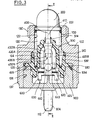
- the contactor illustrated in the appended FIG. 1 comprises a housing 10, a feeler 20, an overtravel spring 30, a pusher 40, a membrane 50, a cup 60, a return spring 70, conductive pads 80, 82 and a plug support 90.
- the contactor has an axis of symmetry referenced 12.
- the housing 10 is centered on this axis 12.
- the support 90 is crimped onto the housing at the rear thereof. It carries the conductive pads 80, 82. These extend parallel to the axis 12.
- the probe 20 is capable of sliding parallel to the axis 12. It emerges outside the housing 10.
- the pusher 40 is housed in the housing 10.
- the overtravel spring 30 is interposed between the probe 20 and the pusher 40.
- the membrane 50 and the cup 60 are placed between the pusher 40 and the conductive pads 80, 82.
- the membrane 50 is pinched at the periphery between the housing 10 and the support plug 90 to ensure the seal between the medium containing the member capable of acting on the probe 20 and the electrical contacts 80, 82.
- the membrane 50 is placed between the cup 60 and the pusher 40.
- the cup 60 which extends transversely to the axis 12 can slide parallel to this axis. At rest, the cup 50 is pushed away from the contact pads 80, 82 by the return spring 70.
- the spring 30 interposed between the probe 20 and the pusher 40 is provided to avoid any deterioration of the cup 60, of the membrane 50 and of the pusher 40 when the movement of the probe 20, towards the inside of the housing, is continued after the cup 60 has reached its position of connection of the pads 80, 82.
- the contactor illustrated in Figure 1 defines an electrical contact open at rest and closed at work.
- the contactors of this second type open to work, differ from that illustrated in FIG. 1 by the fact that the relative position of the contact pads 80, 82 and of the cup 60 is reversed relative to the pusher 40 .
- the conventional contactors hitherto proposed cannot in any way be adapted to define either a contact open at rest, or a contact open at work.
- Documents DE-B-1 123 732, EP-A-0 028 000 and EP-A-0 043 618 describe electrical switching systems comprising a housing which carries at least one pair of electrical contacts and which houses a push-button capable of sliding between a rest position and a working position to modify the state of connection of the electrical contacts and a return spring which urges the pusher towards the rest position, in which the pair of electrical contacts comprises at least one element capable of '' be moved transversely to the sliding direction of the pusher when moving it, to open or close the contacts.
- the present invention aims to improve existing switching systems.
- a first object of the present invention is to provide a new contactor structure which guarantees precise relative positioning between the pusher and the electrical contacts to ensure precise position detection of a movable member.
- Another object of the present invention is to propose a new electrical contactor structure capable of defining either a contact open at rest according to a first variant, or a contact open at work according to a second variant, while allowing the use of a maximum of common parts between the two variants.
- Another object of the present invention is to provide a new electrical contactor completely insensitive to ambient pressure.
- Another object of the invention is to propose a new electrical contactor in which the contacts are perfectly isolated from an ambient fluid.
- Another object of the present invention is to provide a new economical and reliable electrical contactor.
- an electrical contactor of the type known per se comprising a housing which carries at least one pair of electrical contacts and which houses a push-piece capable of sliding between a rest position and a position working to modify the state of connection of the electrical contacts, and a return spring which requests the pusher towards the rest position
- the pair of electrical contacts comprises at least one element capable of being moved perpendicular to the sliding direction of the pusher, during its movement, to open or close the contacts
- the contactor further comprises a probe associated, by a friction engagement, with the pusher, and emerging outside the housing, the probe and the pusher being initially capable of relative movement parallel to the axis of the housing, while the housing has an axial stop limiting the movement of the pusher in the direction of the working position, and a guide sleeve has an axial stop limiting the movement of the probe in the direction of the working position, so that the position relative correctness of the feeler and the pusher is obtained when these two
- This arrangement makes it possible to obtain a self-calibration of the electrical contactor in accordance with the present invention, after assembly, that is to say after complete assembly and closing of the contactor, whatever the tolerances of the parts involved in the contactor. .
- the pair of contacts carried by the housing comprises two blades symmetrical with respect to the axis of the housing.
- each of the strips comprises at least one elastic branch extending substantially parallel to the axis and each carrying a contact grain.
- the pusher is guided by sliding by a sleeve which moreover ensures a sealed separation between the medium containing the active member capable of acting on the contactor and the electrical contacts.
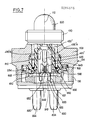
- the electrical contactor according to the present invention illustrated in the appended figures essentially comprises a housing 100, a feeler 200, a control pusher 400, a guide sleeve 500, two contact strips 600, 650 and two studs 800, 820 .
- the contactor has an axis of symmetry 112.
- the end of the latter by which the probe 200 emerges will be called “front end” of the housing 100, and “rear end” of the housing, the end of the latter through which the studs 800, 820.
- the housing 100 has an internal chamber 120 of revolution around the axis 112.
- the chamber 120 is more precisely composed, preferably, of three sections 122, 124 and 126, which succeed one another axially. Sections 122, 124 and 126 have increasing diameters from the front end of the housing to the rear end.
- the housing 100 On its periphery, the housing 100 is provided with two threaded portions 130, 132, respectively adjacent to the front end and to the rear end. Between the threads 130, 132, the housing 100 is provided with an intermediate zone 134 of hexagonal cross section or equivalent to allow assembly of the housing by threading in an associated device.
- the housing 100 further has on its internal surface and at its front end an annular rib 128.
- This annular rib 128 is formed projecting from the internal surface of the front section 122, in position adjacent to the front surface 136 of the housing , transverse to axis 112.
- the rib 128 serves as a stop for the probe 200 as illustrated in FIG. 2.
- the probe 200 is formed in one piece. Essentially, it comprises a semi-spherical cap 210, which is extended towards the rear by a cylinder 220 centered on the axis 112. The cap 210 and the cylinder 220 define in combination a chamber 230 open towards the rear .
- the external diameter of the cylinder 220 corresponds with a certain play to the internal diameter of the rib 128. Furthermore, the cylinder 220 is provided, on its external periphery and in position adjacent to its rear end, with an annular rib 222. The rib 222 has an external diameter substantially equal to the internal diameter of the smallest section 122 of the chamber 120 of the housing and guides the probe 200.
- the probe 200 can be introduced into the chamber 120 of the housing 100, and emerge on the front end of the latter, the movement of the probe 200 towards the front relative to the housing 100 being limited when the rib 222 comes to rest against the rib 128 of the housing.
- the hemispherical cap 210 To avoid any compression of the fluid contained in the chamber 120 of the housing during the movement of the probe 200, it is provided at the hemispherical cap 210 with a plurality of through openings 212, 214, 216 equi-distributed around axis 112.
- the hemispherical cap 210 is provided on its internal surface with a barrel 217 centered on the axis 112.
- the barrel 217 defines an internal cylindrical housing 218 centered on the axis 112 and open towards the rear.
- the housing 218 is intended to receive, as illustrated in FIG. 2, the front end of the pusher 400.
- the pusher 400 essentially has a straight 410 trunk centered on the axis 112, extended rearward by two pairs of arms 420A, 420B on the one hand, 430A, 430B on the other hand.
- the arms 420, 430 extend essentially parallel to the axis 112. At each pair, the arms 420, 430 are symmetrical with respect to the axis 112.
- the arms 420 are intended to cooperate with the contact strips 600, 650 to modify the state of connection of the latter.
- the arms 430 are intended to guide the pusher 400 during its sliding.
- the control arms 420 are longer as the guide arms 430.
- the rear surface of the guide arms 430A, 430B, which is transverse to the axis 112 is referenced 432A, 432B. It will be noted that the guide arms 430 are provided, on their outer surface 434, and in position adjacent to the aforementioned rear surface 432, with recesses 436. These recesses 436 are intended to receive a tip 802, 822 formed on the pads 800 , 820 when the pusher is moved backwards against an axial stop integral with the housing, during the calibration phase.
- each control arm 420 is composed of two canvases 421, 422 planar and elongated parallel to the axis 112, which terminate towards the rear by a block 425
- the fabric 421 extends substantially radially relative to the axis 112.
- the fabric 422 is integral with the fabric 421. It is placed on the outside of the latter and extends transversely to a radius drawn up from the axis 112.
- the rear end of the control arms 420 which is defined by the block 425 is delimited by two lateral surfaces 423, 424.
- the lateral surfaces 423, 424 are defined by generatrices transverse to the axis 112.
- the lateral surfaces 423, 424 converge symmetrically towards the rear.
- the block 425 is delimited towards the front, opposite the internal fabric 421 by two lateral surfaces 426, 427.
- the surfaces 426, 427 are delimited by generatrices transversal to the axis 112.
- the lateral surfaces 426, 427 converge symmetrically forward.
- the trunk 410 of the pusher 400 is provided on its front end with a barrel 412 provided with longitudinal grooves.
- the barrel 412 is intended to enter the housing 218 formed in the probe 200 to be held thereon by friction.
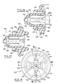
- the guide sleeve 500 has a symmetry with respect to the axis 112. It comprises a main sheath 510 defined by a generally cylindrical envelope centered on the axis 112.
- the sheath 510 has an internal housing 512.
- This housing 512 receives the arms of control 420 and the guide arms 430.
- the housing 512 has a straight section in the shape of a four-pointed star, referenced 514, 516, 518 and 520 in FIG. 18.
- the straight section of the housing 512 is complementary to the envelope control arms 420 and guide arms 430.
- the front end 522 of the sheath is provided with an annular lip 524 which converges towards the axis 512, towards the front.
- the lip 524 is intended to tightly tighten the cylindrical trunk 410 of the pusher 400.
- the main sheath 510 is moreover provided, on its outer periphery and at its rear end, with a flange 530 in the general shape of a crown transverse to the axis 112.
- the flange 530 is adapted to be pinched, at the level of its outer periphery, between the housing 100 and the plug 900 supporting the studs 800, 820. More precisely still the flange 530, as illustrated in the figures, is pinched between the recess 125 transverse to the axis 112 defined on the housing between the sections 124, 126 of the housing 120 on the one hand, and the support plug 900 on the other hand.
- the flange 530 carries on the outer periphery of the main sleeve 510 a cylindrical lip seal 532.
- the seal 532 is directed forward. It is engaged in section 124 of housing 120 and adapted to be pressed against the internal surface of section 124.
- the fluid can penetrate into the housing 120 via the openings 212, 214 and 216 formed in the probe 200.
- the pressure of the fluid which is applied to the internal periphery 533 of the cylindrical seal 532 tends to press the seal 532 tightly against the surface 124 of the housing 120.
- the flange 530 is provided with a second cylindrical lip seal 534.
- the seal 534 extends towards the rear. It is intended to be pressed against the conical front surface of the support cap 900.
- the guide sleeve 500 must ensure precise angular positioning of the pusher 400 relative to the contact strips 600, 650. Therefore, the sleeve 500 must be precisely angularly positioned relative to the support plug 900.
- the angular positioning of the sleeve 500 is defined on the one hand by two pins 540, 542 projecting from the rear surface of the flange 530, on the other hand by two housings 544, 546 also provided on the rear surface of the flange 530.
- the pins 540, 542 are diametrically opposite and intended to penetrate into complementary chambers formed in the support plug 900.
- the housings 544, 546 are also diametrically opposite and angularly offset by 90 ° relative to the pins 540, 542 mentioned above.
- the housings 544, 546 are engaged on diametrically opposite ribs 902, 904, formed on the support plug 900.
- guide sleeve 500 is further provided, on the rear surface of the flange 530 with two other diametrically opposite housings 550, 552 which receive the end pieces 802, 822 of the contact pads.
- the guide sleeve 500 defines, on its outer periphery and in position adjacent to its front end, a level of the connection zone between the main sleeve 510 and the joint 524, a surface 560 in the form of a crown transverse to the axis 112. This surface 560 is directed towards the front and is intended to serve as an axial stop limiting the movement of the probe 200 towards the interior of the housing 100, during the calibration phase initial.
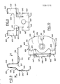
- the electrical contactor according to the present invention illustrated in the appended figures comprises two identical strips 600, 650. These strips have a symmetry with respect to a plane passing through the axis 112. We will now describe the struc ture of the strip 600 opposite Figures 8, 9 and 10 attached.
- the strip 600 comprises a fixing plate 610, two elastic wings 620, 630 in the shape of a "U”, and a contact pallet 640.
- the fixing plate 610 extends perpendicular to the axis 112. It is provided with a cylindrical opening 612 defined at the level of a collar 614 of frustoconical shape produced by deformation of the plate 610.
- the collar 614 extends towards the front relative to the fixing plate 610.
- the diameter of the opening 612 is complementary to the diameter of the end pieces 802, 822 formed on the front end of the studs 800, 820.
- the collars 614 can be driven out on the bits 802, 822 to ensure a reliable electrical connection between the electrically conductive strips 600, 650 and the pads 800, 820.
- the fixing plate 610 is provided on its outer edge 615 with a cutout 616 adapted to receive the ribs 902, 904 provided on the support plug 900.
- the cooperation thus defined between the ribs 902, 904 and the cutouts 616 ensures immobilization in rotation of the strips 600, 650 on the support plug 900, and therefore precise positioning of the strips.
- the elastic wings 620, 630 are connected to the internal edge of the fixing plate 610 in the vicinity of its lateral edges 618, 619.
- Each of the elastic wings 620, 630 is composed of two branches 621, 622, on the one hand, and 631, 632 on the other hand.
- the branches 621, 631 extend rearward, substantially parallel to the axis 112.
- the wings 622, 632 extend forward, substantially parallel to the axis 112.
- the branches 621, 622 of a on the other hand, 631, 632 on the other hand, are connected by a curved portion 623, 633.
- the contact paddle 640 has the general shape of an "I" composed of a central core 641 and two cross members 643, 644 which will be referred to hereinafter rear and front respectively taking into account their positioning in the contactor.
- the rear crossmember 643 extends transversely to the axis 112 and connects the two branches 622, 632. It will also be noted on examining FIG. 9 that it converges towards the axis 112 in approach to the central core 641, either towards the front.
- the central core 641 extends substantially parallel to the axis 112.
- the front crossmember 644 extends essentially transversely to the axis 112. It is provided with a central contact pad 642.
- the two pads 642 carried respectively by the strips 600, 650 are intended to come into contact.
- the axes of the pads 642 are transverse to the axis 112 of the housing and intersecting this axis.
- the separation of the pads 642 is effected by the pusher 400, when the rear end of the latter spreads the contact pallets 640.
- the free edge front 645 of the front crossmember 644 is curved outward.
- the free rear edges 646, 647 of the front crossmember 644 are placed res pectively on either side of the central core 641, are inclined towards the outside.
- the return spring 700 is a helical spring. It is engaged between the feeler 200 and the guide sleeve 500. More specifically, the rear end of the return spring 700 is engaged between the outer periphery of the main sheath 510 and the inner periphery of the cylindrical seal 532. The return spring 700 rests against the front surface of the flange 530.
- the support plug 900 is molded on the two conductive pads 800, 820. It will be noted that only these pads 800, 820 and the contact strips 600, 650 are made of electrically conductive material.
- the other elements, housing 100, feeler 200, pusher 400, guide sleeve 500 and support plug 900 are made of electrically insulating material.
- the studs 800, 820 are formed of generally cylindrical bodies whose axes 804, 824 are parallel to the axis 112 and diametrically opposite with respect thereto.
- the studs 800, 820 are provided on their outer periphery with annular ribs 805, 806, 825, 826 defining a rigid connection between the studs 800, 820 and the shutter plug 900, in particular by preventing any translational movement of the studs 800, 820 by compared to the support cap 900.
- the pads 800, 820 emerge widely on the rear surface 906 of the support plug 900.
- the studs 800, 820 are provided with ends 802, 822 of cylindrical envelope, of smaller section, centered on the axes 804, 824.
- the ends 802, 822 are engaged in the collars 614 to provide an electrical connection between the pads 800, 820 and the lamellae 600, 650 respectively associated.
- the support plug 900 has the general shape of a disc. It is fixed to the housing 100 in the section 126 of the housing 120 by any suitable means, for example by crimping, welding, screwing or the like.
- the support plug 900 is provided with a chamber 910 centered on the axis 112 and opening onto its front surface. This chamber 910 is intended to receive the contact strips 600, 650 while ensuring free bending of the elastic wings 620, 630, as well as the rear end of the pusher 400.
- the cylindrical seal 524 seals on the periphery of the pusher 400 passing through the sleeve 500. Furthermore, the cylindrical seals 532, 534 seal between the housing 100 and the support plug 900. Thus, the seals 524, 532, 534 effectively isolate the contact strips 600, 650 and the pads 800, 820 from the pressurized fluid in which bathes the probe 200.
- the return spring 700 pushes the feeler 200 against the front rib 128.
- the slats 600 and 650 are pinched at the level of the fixing plate 610 between the rear face of the sleeve 500 and the front face of the terminals 800 and 820 to allow the take-up of play and to obtain a precise and stable positioning of the slats 600 and 650.
- the front barrel 412 of the pusher 400 penetrates only slightly into the associated housing 218 of the probe 200.
- the initial position of the elements is illustrated in the right half view of FIG. 6.
- the probe 200 is moved as far as possible towards the inside of the housing 100.
- the pusher 400 is biased towards the inside of the housing 100.
- the movement of the pusher 400 is limited when the surfaces rear 432 of the guide arms 430 come to rest against the fixing plates 610 as illustrated on the left of FIG. 6.
- the movement of the probe 200 is interrupted when the rear surface 224 of the latter comes to rest against the surface d support 560 of the guide plug 500.
- the pusher 400 is thus immobilized with respect to the feeler 200. Its relative position is obtained with precision thanks to the defined support, on the one hand, between the feeler 200 and the guide sleeve 500, on the other hand part, between the pusher 400 itself and the fixing plates 610.
- the return spring 700 biases the feeler 200 forwards against the rib 128.
- the widest part of the blocks 425 provided at the rear end of the control arms 420 is placed between the front crosspieces 644 of the contact vanes 640 of the strips 600, 650, as illustrated in FIG. 2.
- the aforementioned largest widening of the blocks 425 is referenced L in FIG. 11. It is defined between the zone 428 of connection between the surfaces 423, 426 on the one hand, and the zone 429 of connection between the surfaces 424, 427 of somewhere else.
- the aforementioned large flaring L of the blocks 425 is greater than twice the thickness of the pads 642 carried by the contact strips 600, 650.
- the large flaring L of the blocks 425 is placed between the front crosspieces 644, 640, the two contact pads 642 are separated.
- the switch formed between the pads 800, 820 is therefore open.
- the block 425 provided at the rear end of the control arms 420 passes beyond, towards the rear, the front crossmember 644 of the contact paddles 640.
- the fabrics 422 of the control arms 420 are placed towards the outside of the front crossmember 644.
- the width 1 of the fabrics 421 is less than twice the thickness of the contact grains 642.
- the return spring 700 pushes back the probe 200 and the pusher 400 which is linked to it via the barrel 412, towards the front, bearing against the rib 128.
- the blocks 425 are thus brought back between the crosspieces 644 of the contact pallets 640, in order to separate the contact grains 642 again.
- the blocks 425 do not risk polluting the pads 642 by depositing material thereon.
- the edges 645, 646 and 647 curved towards the outside of the contact pallets 640 facilitate the displacement of the blocks 425 between the pallets 640.
- the modification of the electrical state contactor plate is operated by displacement of the contact vanes 640, transverse to the axis 112, thanks to the elasticity of the wings 620, 630. With this arrangement, it is not necessary to provide an overtravel spring in the contactor. Indeed, a displacement of the feeler 200 and of the pusher 400, greater than normal, cannot in any way damage the strips 600, 650.
- the contactor which has just been described corresponds to a contact state open at rest and closed at work.
- This contactor can easily be adapted to define a state of contact closed at rest and open to work by replacing the pusher 400 previously described and illustrated in FIGS. 11, 12 and 13 by the pusher 400 ⁇ illustrated in FIGS. 14 and 15.
- the pusher 400 ⁇ illustrated in FIGS. 14 and 15 also comprises a trunk 410 ⁇ centered on the axis 112, a pair of control arms 420 ⁇ A, 420 ⁇ B and a pair of guide arms 430 ⁇ A, 430 ⁇ B.
- the guide arms 430 ⁇ are identical to the aforementioned guide arms 430 and will therefore not be described in more detail below.
- control arms 420 ⁇ A, 420 ⁇ B are shorter than the aforementioned arms 420.
- the control arms 420 ⁇ are formed of a straight rod extending parallel to the axis 112. These rods 420 ⁇ have a constant width L corresponding to the largest flare L of the abovementioned blocks 425.
- the rear end of the 420 ⁇ control arms is tapered. It is defined by two lateral surfaces 423 ⁇ , 424 ⁇ , which converge symmetrically towards the rear.
- the length of the control arms 420 ⁇ is adapted so that in the rest position, when the feeler 200 is pushed against the rib 128 by the return spring 700, the end surfaces 423 ⁇ , 424 ⁇ of the control arms 420 ⁇ are placed in front of the crosspieces 644. Thus, the studs 642 are elastically stressed in contact. On the other hand, when the feeler 200 and the associated push-button 400 ⁇ are moved rearward, the control arms 420 ⁇ penetrate between the crosspieces 644 to separate the contact pads 642.
- the spring 700 pushes the feeler 200 and the associated push-button 400 ⁇ forwards again to allow the grains 642 to be brought into contact.
- the pushers 400 can also be adapted to define different successive states of the contacts during the movement of the probe 200.
- the pusher 400 illustrated in FIGS. 11, 12 and 13 could be equipped with two blocks 425 spaced longitudinally to successively define a rest position with open contact, when the rearmost block 425 is placed between the crosspieces 644, a first working position with closed contact, when the fabrics 421 are placed between the crosspieces 644 and finally a second working position with open contact when the most forward block 425 is placed between the crosspieces 644.
- the probe 200 is made of polyamide loaded with 30% glass fibers and 15% with phenylene polysulfone
- the pusher 400 is made of polyamide
- - the guide sleeve 500 is made of flexible polyethylene terephthalate 55 shore.
- the contactor according to the invention has a small number of parts. That moreover, apart from the pusher 400, all the parts making up the contactor are common to the two variants, open at rest and closed at rest.
- the contactor is completely insensitive to pressure fluctuations. It defines a certain insulation between the fluid and the electrical contacts.
- the contactor according to the invention does not require an overtravel spring.
- the elements forming an annular lip seal 524, 532 and 534 provided on the sleeve 500 have a small radial thickness, in order to be flexible and to be applied elastically respectively against the body 410 of the pusher 400, the internal surface 124 of the housing and the front surface plug 900.
- the sleeve 500 serves as a stop for the feeler 200 at its surface 560, it works in the axial direction, that is to say in the direction of its greatest thickness, and is therefore rigid to limit precisely the movement of the probe 200.
Applications Claiming Priority (2)
| Application Number | Priority Date | Filing Date | Title |
|---|---|---|---|
| FR8704288A FR2613119A1 (fr) | 1987-03-27 | 1987-03-27 | Contacteur electrique de position |
| FR8704288 | 1987-03-27 |
Publications (2)
| Publication Number | Publication Date |
|---|---|
| EP0284515A1 true EP0284515A1 (de) | 1988-09-28 |
| EP0284515B1 EP0284515B1 (de) | 1992-06-10 |
Family
ID=9349496
Family Applications (1)
| Application Number | Title | Priority Date | Filing Date |
|---|---|---|---|
| EP19880400722 Expired - Lifetime EP0284515B1 (de) | 1987-03-27 | 1988-03-24 | Elektrischer Positionsschalter |
Country Status (3)
| Country | Link |
|---|---|
| EP (1) | EP0284515B1 (de) |
| DE (1) | DE3871837T2 (de) |
| FR (1) | FR2613119A1 (de) |
Families Citing this family (1)
| Publication number | Priority date | Publication date | Assignee | Title |
|---|---|---|---|---|
| DE19808060A1 (de) * | 1998-02-26 | 1999-09-09 | Euchner Gmbh & Co | Grenztaster |
Citations (5)
| Publication number | Priority date | Publication date | Assignee | Title |
|---|---|---|---|---|
| US2239426A (en) * | 1939-04-19 | 1941-04-22 | Gen Electric | Electric switch |
| US2753413A (en) * | 1953-09-28 | 1956-07-03 | Airtron Inc | Quick break electric switches |
| DE1123732B (de) * | 1960-01-07 | 1962-02-15 | Standard Elektrik Lorenz Ag | Drucktaste oder Drucktastenschalter, insbesondere fuer Fernmeldeanlagen, mit einem die Schaltfolge beeinflussenden Glied |
| EP0028000A1 (de) * | 1979-10-30 | 1981-05-06 | Siemens Aktiengesellschaft | Drucktaste |
| EP0043618A1 (de) * | 1980-07-08 | 1982-01-13 | Philips Electronics Uk Limited | Druckknopfschalter |
-
1987
- 1987-03-27 FR FR8704288A patent/FR2613119A1/fr active Pending
-
1988
- 1988-03-24 EP EP19880400722 patent/EP0284515B1/de not_active Expired - Lifetime
- 1988-03-24 DE DE19883871837 patent/DE3871837T2/de not_active Expired - Lifetime
Patent Citations (5)
| Publication number | Priority date | Publication date | Assignee | Title |
|---|---|---|---|---|
| US2239426A (en) * | 1939-04-19 | 1941-04-22 | Gen Electric | Electric switch |
| US2753413A (en) * | 1953-09-28 | 1956-07-03 | Airtron Inc | Quick break electric switches |
| DE1123732B (de) * | 1960-01-07 | 1962-02-15 | Standard Elektrik Lorenz Ag | Drucktaste oder Drucktastenschalter, insbesondere fuer Fernmeldeanlagen, mit einem die Schaltfolge beeinflussenden Glied |
| EP0028000A1 (de) * | 1979-10-30 | 1981-05-06 | Siemens Aktiengesellschaft | Drucktaste |
| EP0043618A1 (de) * | 1980-07-08 | 1982-01-13 | Philips Electronics Uk Limited | Druckknopfschalter |
Also Published As
| Publication number | Publication date |
|---|---|
| EP0284515B1 (de) | 1992-06-10 |
| DE3871837D1 (de) | 1992-07-16 |
| FR2613119A1 (fr) | 1988-09-30 |
| DE3871837T2 (de) | 1992-12-03 |
Similar Documents
| Publication | Publication Date | Title |
|---|---|---|
| FR2758662A1 (fr) | Element de connecteur electrique coaxial a contact mobile et connecteur electrique coaxial comprenant un tel element de connecteur | |
| EP0050575A1 (de) | Elektrischer Verbinder mit schneller Verriegelung und Entriegelung | |
| FR2781934A1 (fr) | Element de connecteur coaxial comportant un raccord pour relier le conducteur central d'un cable coaxial au contact central de l'element de connecteur | |
| EP0491626A1 (de) | Elektrischer Koaxialverbinder | |
| FR2624313A1 (de) | ||
| FR2760137A1 (fr) | Connecteur electrique coaxial | |
| EP0157666A1 (de) | Rotationspotentiometer, insbesondere für Winkelpositionsmessung | |
| FR2901066A1 (fr) | Connecteur coaxial | |
| FR2654268A1 (fr) | Dispositif d'etancheite d'entree de cable dans un element de connecteur alveolaire multicontacts. | |
| EP0284515B1 (de) | Elektrischer Positionsschalter | |
| EP0500466B1 (de) | Verschluss für die Kontaktaufnahme eines elektrischen oder optischen Steckverbinders | |
| EP0633629B1 (de) | Verbindungssystem | |
| FR2466093A1 (fr) | Thermo-rupteur | |
| EP2143174A1 (de) | Rückschalen-zubehörteil für einen steckverbinder | |
| EP0539250B1 (de) | Elektrischer Verbinder | |
| FR2644928A1 (fr) | Manette de commande en particulier pour vehicules automobiles comportant deux bagues rotatives | |
| EP0084488A1 (de) | Radachse und Ansatzstück für deren Herstellung | |
| FR2579837A1 (fr) | Serre-cable pour installations electriques | |
| EP0775916A1 (de) | Testanordnung für elektrische Verbinder | |
| EP1146606A1 (de) | Koaxiale elektrische Verbindereinheit mit zusätzlicher Schaltfunktion | |
| FR2681733A1 (fr) | Contact femelle a palette elastique et palette pour un tel contact. | |
| FR2717003A1 (fr) | Dispositif de commutation pour ouvrir et fermer une ligne électrique. | |
| FR2707719A1 (fr) | Embout pour témoin d'usure de garniture de friction, notamment de plaquette de frein. | |
| EP0121637B1 (de) | Gerades elektrisches Anschlussendstück | |
| FR2514552A1 (fr) | Commutateur rotatif a positions multiples |
Legal Events
| Date | Code | Title | Description |
|---|---|---|---|
| PUAI | Public reference made under article 153(3) epc to a published international application that has entered the european phase |
Free format text: ORIGINAL CODE: 0009012 |
|
| AK | Designated contracting states |
Kind code of ref document: A1 Designated state(s): DE ES FR GB IT |
|
| 17P | Request for examination filed |
Effective date: 19881121 |
|
| 17Q | First examination report despatched |
Effective date: 19910618 |
|
| GRAA | (expected) grant |
Free format text: ORIGINAL CODE: 0009210 |
|
| AK | Designated contracting states |
Kind code of ref document: B1 Designated state(s): DE ES FR GB IT |
|
| PG25 | Lapsed in a contracting state [announced via postgrant information from national office to epo] |
Ref country code: GB Effective date: 19920610 Ref country code: ES Free format text: THE PATENT HAS BEEN ANNULLED BY A DECISION OF A NATIONAL AUTHORITY Effective date: 19920610 |
|
| REF | Corresponds to: |
Ref document number: 3871837 Country of ref document: DE Date of ref document: 19920716 |
|
| ITF | It: translation for a ep patent filed |
Owner name: SOCIETA' ITALIANA BREVETTI S.P.A. |
|
| GBV | Gb: ep patent (uk) treated as always having been void in accordance with gb section 77(7)/1977 [no translation filed] | ||
| PLBE | No opposition filed within time limit |
Free format text: ORIGINAL CODE: 0009261 |
|
| STAA | Information on the status of an ep patent application or granted ep patent |
Free format text: STATUS: NO OPPOSITION FILED WITHIN TIME LIMIT |
|
| 26N | No opposition filed | ||
| PGFP | Annual fee paid to national office [announced via postgrant information from national office to epo] |
Ref country code: FR Payment date: 19940228 Year of fee payment: 7 |
|
| PGFP | Annual fee paid to national office [announced via postgrant information from national office to epo] |
Ref country code: DE Payment date: 19940326 Year of fee payment: 7 |
|
| PG25 | Lapsed in a contracting state [announced via postgrant information from national office to epo] |
Ref country code: FR Free format text: LAPSE BECAUSE OF NON-PAYMENT OF DUE FEES Effective date: 19951130 |
|
| PG25 | Lapsed in a contracting state [announced via postgrant information from national office to epo] |
Ref country code: DE Effective date: 19951201 |
|
| REG | Reference to a national code |
Ref country code: FR Ref legal event code: ST |
|
| PG25 | Lapsed in a contracting state [announced via postgrant information from national office to epo] |
Ref country code: IT Free format text: LAPSE BECAUSE OF NON-PAYMENT OF DUE FEES;WARNING: LAPSES OF ITALIAN PATENTS WITH EFFECTIVE DATE BEFORE 2007 MAY HAVE OCCURRED AT ANY TIME BEFORE 2007. THE CORRECT EFFECTIVE DATE MAY BE DIFFERENT FROM THE ONE RECORDED. Effective date: 20050324 |