EP0284515A1 - Electrical position switch - Google Patents
Electrical position switch Download PDFInfo
- Publication number
- EP0284515A1 EP0284515A1 EP88400722A EP88400722A EP0284515A1 EP 0284515 A1 EP0284515 A1 EP 0284515A1 EP 88400722 A EP88400722 A EP 88400722A EP 88400722 A EP88400722 A EP 88400722A EP 0284515 A1 EP0284515 A1 EP 0284515A1
- Authority
- EP
- European Patent Office
- Prior art keywords
- housing
- pusher
- axis
- contact
- electrical
- Prior art date
- Legal status (The legal status is an assumption and is not a legal conclusion. Google has not performed a legal analysis and makes no representation as to the accuracy of the status listed.)
- Granted
Links
Images


Classifications
-
- H—ELECTRICITY
- H01—ELECTRIC ELEMENTS
- H01H—ELECTRIC SWITCHES; RELAYS; SELECTORS; EMERGENCY PROTECTIVE DEVICES
- H01H15/00—Switches having rectilinearly-movable operating part or parts adapted for actuation in opposite directions, e.g. slide switch
- H01H15/02—Details
- H01H15/06—Movable parts; Contacts mounted thereon
- H01H15/10—Operating parts
- H01H15/102—Operating parts comprising cam devices
Definitions
- the present invention relates to the field of electrical contactors, in particular for the detection of limit switches for moving parts.
- the present invention finds particular application in the automotive field, for example, in the design of gearboxes.
- the present invention is not limited to this application.
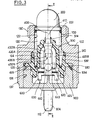
- the contactor illustrated in the appended FIG. 1 comprises a housing 10, a feeler 20, an overtravel spring 30, a pusher 40, a membrane 50, a cup 60, a return spring 70, conductive pads 80, 82 and a plug support 90.
- the contactor has an axis of symmetry referenced 12.
- the housing 10 is centered on this axis 12.
- the support 90 is crimped onto the housing at the rear thereof. It carries the conductive pads 80, 82. These extend parallel to the axis 12.
- the probe 20 is capable of sliding parallel to the axis 12. It emerges outside the housing 10.
- the pusher 40 is housed in the housing 10.
- the overtravel spring 30 is interposed between the probe 20 and the pusher 40.
- the membrane 50 and the cup 60 are placed between the pusher 40 and the conductive pads 80, 82.
- the membrane 50 is pinched at the periphery between the housing 10 and the support plug 90 to ensure the seal between the medium containing the member capable of acting on the probe 20 and the electrical contacts 80, 82.
- the membrane 50 is placed between the cup 60 and the pusher 40.
- the cup 60 which extends transversely to the axis 12 can slide parallel to this axis. At rest, the cup 50 is pushed away from the contact pads 80, 82 by the return spring 70.
- the spring 30 interposed between the probe 20 and the pusher 40 is provided to avoid any deterioration of the cup 60, of the membrane 50 and of the pusher 40 when the movement of the probe 20, towards the inside of the housing, is continued after the cup 60 has reached its position of connection of the pads 80, 82.
- the contactor illustrated in Figure 1 defines an electrical contact open at rest and closed at work.
- the contactors of this second type open to work, differ from that illustrated in FIG. 1 by the fact that the relative position of the contact pads 80, 82 and of the cup 60 is reversed relative to the pusher 40 .
- the conventional contactors hitherto proposed cannot in any way be adapted to define either a contact open at rest, or a contact open at work.
- Documents DE-B-1 123 732, EP-A-0 028 000 and EP-A-0 043 618 describe electrical switching systems comprising a housing which carries at least one pair of electrical contacts and which houses a push-button capable of sliding between a rest position and a working position to modify the state of connection of the electrical contacts and a return spring which urges the pusher towards the rest position, in which the pair of electrical contacts comprises at least one element capable of '' be moved transversely to the sliding direction of the pusher when moving it, to open or close the contacts.
- the present invention aims to improve existing switching systems.
- a first object of the present invention is to provide a new contactor structure which guarantees precise relative positioning between the pusher and the electrical contacts to ensure precise position detection of a movable member.
- Another object of the present invention is to propose a new electrical contactor structure capable of defining either a contact open at rest according to a first variant, or a contact open at work according to a second variant, while allowing the use of a maximum of common parts between the two variants.
- Another object of the present invention is to provide a new electrical contactor completely insensitive to ambient pressure.
- Another object of the invention is to propose a new electrical contactor in which the contacts are perfectly isolated from an ambient fluid.
- Another object of the present invention is to provide a new economical and reliable electrical contactor.
- an electrical contactor of the type known per se comprising a housing which carries at least one pair of electrical contacts and which houses a push-piece capable of sliding between a rest position and a position working to modify the state of connection of the electrical contacts, and a return spring which requests the pusher towards the rest position
- the pair of electrical contacts comprises at least one element capable of being moved perpendicular to the sliding direction of the pusher, during its movement, to open or close the contacts
- the contactor further comprises a probe associated, by a friction engagement, with the pusher, and emerging outside the housing, the probe and the pusher being initially capable of relative movement parallel to the axis of the housing, while the housing has an axial stop limiting the movement of the pusher in the direction of the working position, and a guide sleeve has an axial stop limiting the movement of the probe in the direction of the working position, so that the position relative correctness of the feeler and the pusher is obtained when these two
- This arrangement makes it possible to obtain a self-calibration of the electrical contactor in accordance with the present invention, after assembly, that is to say after complete assembly and closing of the contactor, whatever the tolerances of the parts involved in the contactor. .
- the pair of contacts carried by the housing comprises two blades symmetrical with respect to the axis of the housing.
- each of the strips comprises at least one elastic branch extending substantially parallel to the axis and each carrying a contact grain.
- the pusher is guided by sliding by a sleeve which moreover ensures a sealed separation between the medium containing the active member capable of acting on the contactor and the electrical contacts.
- the electrical contactor according to the present invention illustrated in the appended figures essentially comprises a housing 100, a feeler 200, a control pusher 400, a guide sleeve 500, two contact strips 600, 650 and two studs 800, 820 .
- the contactor has an axis of symmetry 112.
- the end of the latter by which the probe 200 emerges will be called “front end” of the housing 100, and “rear end” of the housing, the end of the latter through which the studs 800, 820.
- the housing 100 has an internal chamber 120 of revolution around the axis 112.
- the chamber 120 is more precisely composed, preferably, of three sections 122, 124 and 126, which succeed one another axially. Sections 122, 124 and 126 have increasing diameters from the front end of the housing to the rear end.
- the housing 100 On its periphery, the housing 100 is provided with two threaded portions 130, 132, respectively adjacent to the front end and to the rear end. Between the threads 130, 132, the housing 100 is provided with an intermediate zone 134 of hexagonal cross section or equivalent to allow assembly of the housing by threading in an associated device.
- the housing 100 further has on its internal surface and at its front end an annular rib 128.
- This annular rib 128 is formed projecting from the internal surface of the front section 122, in position adjacent to the front surface 136 of the housing , transverse to axis 112.
- the rib 128 serves as a stop for the probe 200 as illustrated in FIG. 2.
- the probe 200 is formed in one piece. Essentially, it comprises a semi-spherical cap 210, which is extended towards the rear by a cylinder 220 centered on the axis 112. The cap 210 and the cylinder 220 define in combination a chamber 230 open towards the rear .
- the external diameter of the cylinder 220 corresponds with a certain play to the internal diameter of the rib 128. Furthermore, the cylinder 220 is provided, on its external periphery and in position adjacent to its rear end, with an annular rib 222. The rib 222 has an external diameter substantially equal to the internal diameter of the smallest section 122 of the chamber 120 of the housing and guides the probe 200.
- the probe 200 can be introduced into the chamber 120 of the housing 100, and emerge on the front end of the latter, the movement of the probe 200 towards the front relative to the housing 100 being limited when the rib 222 comes to rest against the rib 128 of the housing.
- the hemispherical cap 210 To avoid any compression of the fluid contained in the chamber 120 of the housing during the movement of the probe 200, it is provided at the hemispherical cap 210 with a plurality of through openings 212, 214, 216 equi-distributed around axis 112.
- the hemispherical cap 210 is provided on its internal surface with a barrel 217 centered on the axis 112.
- the barrel 217 defines an internal cylindrical housing 218 centered on the axis 112 and open towards the rear.
- the housing 218 is intended to receive, as illustrated in FIG. 2, the front end of the pusher 400.
- the pusher 400 essentially has a straight 410 trunk centered on the axis 112, extended rearward by two pairs of arms 420A, 420B on the one hand, 430A, 430B on the other hand.
- the arms 420, 430 extend essentially parallel to the axis 112. At each pair, the arms 420, 430 are symmetrical with respect to the axis 112.
- the arms 420 are intended to cooperate with the contact strips 600, 650 to modify the state of connection of the latter.
- the arms 430 are intended to guide the pusher 400 during its sliding.
- the control arms 420 are longer as the guide arms 430.
- the rear surface of the guide arms 430A, 430B, which is transverse to the axis 112 is referenced 432A, 432B. It will be noted that the guide arms 430 are provided, on their outer surface 434, and in position adjacent to the aforementioned rear surface 432, with recesses 436. These recesses 436 are intended to receive a tip 802, 822 formed on the pads 800 , 820 when the pusher is moved backwards against an axial stop integral with the housing, during the calibration phase.
- each control arm 420 is composed of two canvases 421, 422 planar and elongated parallel to the axis 112, which terminate towards the rear by a block 425
- the fabric 421 extends substantially radially relative to the axis 112.
- the fabric 422 is integral with the fabric 421. It is placed on the outside of the latter and extends transversely to a radius drawn up from the axis 112.
- the rear end of the control arms 420 which is defined by the block 425 is delimited by two lateral surfaces 423, 424.
- the lateral surfaces 423, 424 are defined by generatrices transverse to the axis 112.
- the lateral surfaces 423, 424 converge symmetrically towards the rear.
- the block 425 is delimited towards the front, opposite the internal fabric 421 by two lateral surfaces 426, 427.
- the surfaces 426, 427 are delimited by generatrices transversal to the axis 112.
- the lateral surfaces 426, 427 converge symmetrically forward.
- the trunk 410 of the pusher 400 is provided on its front end with a barrel 412 provided with longitudinal grooves.
- the barrel 412 is intended to enter the housing 218 formed in the probe 200 to be held thereon by friction.
- the guide sleeve 500 has a symmetry with respect to the axis 112. It comprises a main sheath 510 defined by a generally cylindrical envelope centered on the axis 112.
- the sheath 510 has an internal housing 512.
- This housing 512 receives the arms of control 420 and the guide arms 430.
- the housing 512 has a straight section in the shape of a four-pointed star, referenced 514, 516, 518 and 520 in FIG. 18.
- the straight section of the housing 512 is complementary to the envelope control arms 420 and guide arms 430.
- the front end 522 of the sheath is provided with an annular lip 524 which converges towards the axis 512, towards the front.
- the lip 524 is intended to tightly tighten the cylindrical trunk 410 of the pusher 400.
- the main sheath 510 is moreover provided, on its outer periphery and at its rear end, with a flange 530 in the general shape of a crown transverse to the axis 112.
- the flange 530 is adapted to be pinched, at the level of its outer periphery, between the housing 100 and the plug 900 supporting the studs 800, 820. More precisely still the flange 530, as illustrated in the figures, is pinched between the recess 125 transverse to the axis 112 defined on the housing between the sections 124, 126 of the housing 120 on the one hand, and the support plug 900 on the other hand.
- the flange 530 carries on the outer periphery of the main sleeve 510 a cylindrical lip seal 532.
- the seal 532 is directed forward. It is engaged in section 124 of housing 120 and adapted to be pressed against the internal surface of section 124.
- the fluid can penetrate into the housing 120 via the openings 212, 214 and 216 formed in the probe 200.
- the pressure of the fluid which is applied to the internal periphery 533 of the cylindrical seal 532 tends to press the seal 532 tightly against the surface 124 of the housing 120.
- the flange 530 is provided with a second cylindrical lip seal 534.
- the seal 534 extends towards the rear. It is intended to be pressed against the conical front surface of the support cap 900.
- the guide sleeve 500 must ensure precise angular positioning of the pusher 400 relative to the contact strips 600, 650. Therefore, the sleeve 500 must be precisely angularly positioned relative to the support plug 900.
- the angular positioning of the sleeve 500 is defined on the one hand by two pins 540, 542 projecting from the rear surface of the flange 530, on the other hand by two housings 544, 546 also provided on the rear surface of the flange 530.
- the pins 540, 542 are diametrically opposite and intended to penetrate into complementary chambers formed in the support plug 900.
- the housings 544, 546 are also diametrically opposite and angularly offset by 90 ° relative to the pins 540, 542 mentioned above.
- the housings 544, 546 are engaged on diametrically opposite ribs 902, 904, formed on the support plug 900.
- guide sleeve 500 is further provided, on the rear surface of the flange 530 with two other diametrically opposite housings 550, 552 which receive the end pieces 802, 822 of the contact pads.
- the guide sleeve 500 defines, on its outer periphery and in position adjacent to its front end, a level of the connection zone between the main sleeve 510 and the joint 524, a surface 560 in the form of a crown transverse to the axis 112. This surface 560 is directed towards the front and is intended to serve as an axial stop limiting the movement of the probe 200 towards the interior of the housing 100, during the calibration phase initial.
- the electrical contactor according to the present invention illustrated in the appended figures comprises two identical strips 600, 650. These strips have a symmetry with respect to a plane passing through the axis 112. We will now describe the struc ture of the strip 600 opposite Figures 8, 9 and 10 attached.
- the strip 600 comprises a fixing plate 610, two elastic wings 620, 630 in the shape of a "U”, and a contact pallet 640.
- the fixing plate 610 extends perpendicular to the axis 112. It is provided with a cylindrical opening 612 defined at the level of a collar 614 of frustoconical shape produced by deformation of the plate 610.
- the collar 614 extends towards the front relative to the fixing plate 610.
- the diameter of the opening 612 is complementary to the diameter of the end pieces 802, 822 formed on the front end of the studs 800, 820.
- the collars 614 can be driven out on the bits 802, 822 to ensure a reliable electrical connection between the electrically conductive strips 600, 650 and the pads 800, 820.
- the fixing plate 610 is provided on its outer edge 615 with a cutout 616 adapted to receive the ribs 902, 904 provided on the support plug 900.
- the cooperation thus defined between the ribs 902, 904 and the cutouts 616 ensures immobilization in rotation of the strips 600, 650 on the support plug 900, and therefore precise positioning of the strips.
- the elastic wings 620, 630 are connected to the internal edge of the fixing plate 610 in the vicinity of its lateral edges 618, 619.
- Each of the elastic wings 620, 630 is composed of two branches 621, 622, on the one hand, and 631, 632 on the other hand.
- the branches 621, 631 extend rearward, substantially parallel to the axis 112.
- the wings 622, 632 extend forward, substantially parallel to the axis 112.
- the branches 621, 622 of a on the other hand, 631, 632 on the other hand, are connected by a curved portion 623, 633.
- the contact paddle 640 has the general shape of an "I" composed of a central core 641 and two cross members 643, 644 which will be referred to hereinafter rear and front respectively taking into account their positioning in the contactor.
- the rear crossmember 643 extends transversely to the axis 112 and connects the two branches 622, 632. It will also be noted on examining FIG. 9 that it converges towards the axis 112 in approach to the central core 641, either towards the front.
- the central core 641 extends substantially parallel to the axis 112.
- the front crossmember 644 extends essentially transversely to the axis 112. It is provided with a central contact pad 642.
- the two pads 642 carried respectively by the strips 600, 650 are intended to come into contact.
- the axes of the pads 642 are transverse to the axis 112 of the housing and intersecting this axis.
- the separation of the pads 642 is effected by the pusher 400, when the rear end of the latter spreads the contact pallets 640.
- the free edge front 645 of the front crossmember 644 is curved outward.
- the free rear edges 646, 647 of the front crossmember 644 are placed res pectively on either side of the central core 641, are inclined towards the outside.
- the return spring 700 is a helical spring. It is engaged between the feeler 200 and the guide sleeve 500. More specifically, the rear end of the return spring 700 is engaged between the outer periphery of the main sheath 510 and the inner periphery of the cylindrical seal 532. The return spring 700 rests against the front surface of the flange 530.
- the support plug 900 is molded on the two conductive pads 800, 820. It will be noted that only these pads 800, 820 and the contact strips 600, 650 are made of electrically conductive material.
- the other elements, housing 100, feeler 200, pusher 400, guide sleeve 500 and support plug 900 are made of electrically insulating material.
- the studs 800, 820 are formed of generally cylindrical bodies whose axes 804, 824 are parallel to the axis 112 and diametrically opposite with respect thereto.
- the studs 800, 820 are provided on their outer periphery with annular ribs 805, 806, 825, 826 defining a rigid connection between the studs 800, 820 and the shutter plug 900, in particular by preventing any translational movement of the studs 800, 820 by compared to the support cap 900.
- the pads 800, 820 emerge widely on the rear surface 906 of the support plug 900.
- the studs 800, 820 are provided with ends 802, 822 of cylindrical envelope, of smaller section, centered on the axes 804, 824.
- the ends 802, 822 are engaged in the collars 614 to provide an electrical connection between the pads 800, 820 and the lamellae 600, 650 respectively associated.
- the support plug 900 has the general shape of a disc. It is fixed to the housing 100 in the section 126 of the housing 120 by any suitable means, for example by crimping, welding, screwing or the like.
- the support plug 900 is provided with a chamber 910 centered on the axis 112 and opening onto its front surface. This chamber 910 is intended to receive the contact strips 600, 650 while ensuring free bending of the elastic wings 620, 630, as well as the rear end of the pusher 400.
- the cylindrical seal 524 seals on the periphery of the pusher 400 passing through the sleeve 500. Furthermore, the cylindrical seals 532, 534 seal between the housing 100 and the support plug 900. Thus, the seals 524, 532, 534 effectively isolate the contact strips 600, 650 and the pads 800, 820 from the pressurized fluid in which bathes the probe 200.
- the return spring 700 pushes the feeler 200 against the front rib 128.
- the slats 600 and 650 are pinched at the level of the fixing plate 610 between the rear face of the sleeve 500 and the front face of the terminals 800 and 820 to allow the take-up of play and to obtain a precise and stable positioning of the slats 600 and 650.
- the front barrel 412 of the pusher 400 penetrates only slightly into the associated housing 218 of the probe 200.
- the initial position of the elements is illustrated in the right half view of FIG. 6.
- the probe 200 is moved as far as possible towards the inside of the housing 100.
- the pusher 400 is biased towards the inside of the housing 100.
- the movement of the pusher 400 is limited when the surfaces rear 432 of the guide arms 430 come to rest against the fixing plates 610 as illustrated on the left of FIG. 6.
- the movement of the probe 200 is interrupted when the rear surface 224 of the latter comes to rest against the surface d support 560 of the guide plug 500.
- the pusher 400 is thus immobilized with respect to the feeler 200. Its relative position is obtained with precision thanks to the defined support, on the one hand, between the feeler 200 and the guide sleeve 500, on the other hand part, between the pusher 400 itself and the fixing plates 610.
- the return spring 700 biases the feeler 200 forwards against the rib 128.
- the widest part of the blocks 425 provided at the rear end of the control arms 420 is placed between the front crosspieces 644 of the contact vanes 640 of the strips 600, 650, as illustrated in FIG. 2.
- the aforementioned largest widening of the blocks 425 is referenced L in FIG. 11. It is defined between the zone 428 of connection between the surfaces 423, 426 on the one hand, and the zone 429 of connection between the surfaces 424, 427 of somewhere else.
- the aforementioned large flaring L of the blocks 425 is greater than twice the thickness of the pads 642 carried by the contact strips 600, 650.
- the large flaring L of the blocks 425 is placed between the front crosspieces 644, 640, the two contact pads 642 are separated.
- the switch formed between the pads 800, 820 is therefore open.
- the block 425 provided at the rear end of the control arms 420 passes beyond, towards the rear, the front crossmember 644 of the contact paddles 640.
- the fabrics 422 of the control arms 420 are placed towards the outside of the front crossmember 644.
- the width 1 of the fabrics 421 is less than twice the thickness of the contact grains 642.
- the return spring 700 pushes back the probe 200 and the pusher 400 which is linked to it via the barrel 412, towards the front, bearing against the rib 128.
- the blocks 425 are thus brought back between the crosspieces 644 of the contact pallets 640, in order to separate the contact grains 642 again.
- the blocks 425 do not risk polluting the pads 642 by depositing material thereon.
- the edges 645, 646 and 647 curved towards the outside of the contact pallets 640 facilitate the displacement of the blocks 425 between the pallets 640.
- the modification of the electrical state contactor plate is operated by displacement of the contact vanes 640, transverse to the axis 112, thanks to the elasticity of the wings 620, 630. With this arrangement, it is not necessary to provide an overtravel spring in the contactor. Indeed, a displacement of the feeler 200 and of the pusher 400, greater than normal, cannot in any way damage the strips 600, 650.
- the contactor which has just been described corresponds to a contact state open at rest and closed at work.
- This contactor can easily be adapted to define a state of contact closed at rest and open to work by replacing the pusher 400 previously described and illustrated in FIGS. 11, 12 and 13 by the pusher 400 ⁇ illustrated in FIGS. 14 and 15.
- the pusher 400 ⁇ illustrated in FIGS. 14 and 15 also comprises a trunk 410 ⁇ centered on the axis 112, a pair of control arms 420 ⁇ A, 420 ⁇ B and a pair of guide arms 430 ⁇ A, 430 ⁇ B.
- the guide arms 430 ⁇ are identical to the aforementioned guide arms 430 and will therefore not be described in more detail below.
- control arms 420 ⁇ A, 420 ⁇ B are shorter than the aforementioned arms 420.
- the control arms 420 ⁇ are formed of a straight rod extending parallel to the axis 112. These rods 420 ⁇ have a constant width L corresponding to the largest flare L of the abovementioned blocks 425.
- the rear end of the 420 ⁇ control arms is tapered. It is defined by two lateral surfaces 423 ⁇ , 424 ⁇ , which converge symmetrically towards the rear.
- the length of the control arms 420 ⁇ is adapted so that in the rest position, when the feeler 200 is pushed against the rib 128 by the return spring 700, the end surfaces 423 ⁇ , 424 ⁇ of the control arms 420 ⁇ are placed in front of the crosspieces 644. Thus, the studs 642 are elastically stressed in contact. On the other hand, when the feeler 200 and the associated push-button 400 ⁇ are moved rearward, the control arms 420 ⁇ penetrate between the crosspieces 644 to separate the contact pads 642.
- the spring 700 pushes the feeler 200 and the associated push-button 400 ⁇ forwards again to allow the grains 642 to be brought into contact.
- the pushers 400 can also be adapted to define different successive states of the contacts during the movement of the probe 200.
- the pusher 400 illustrated in FIGS. 11, 12 and 13 could be equipped with two blocks 425 spaced longitudinally to successively define a rest position with open contact, when the rearmost block 425 is placed between the crosspieces 644, a first working position with closed contact, when the fabrics 421 are placed between the crosspieces 644 and finally a second working position with open contact when the most forward block 425 is placed between the crosspieces 644.
- the probe 200 is made of polyamide loaded with 30% glass fibers and 15% with phenylene polysulfone
- the pusher 400 is made of polyamide
- - the guide sleeve 500 is made of flexible polyethylene terephthalate 55 shore.
- the contactor according to the invention has a small number of parts. That moreover, apart from the pusher 400, all the parts making up the contactor are common to the two variants, open at rest and closed at rest.
- the contactor is completely insensitive to pressure fluctuations. It defines a certain insulation between the fluid and the electrical contacts.
- the contactor according to the invention does not require an overtravel spring.
- the elements forming an annular lip seal 524, 532 and 534 provided on the sleeve 500 have a small radial thickness, in order to be flexible and to be applied elastically respectively against the body 410 of the pusher 400, the internal surface 124 of the housing and the front surface plug 900.
- the sleeve 500 serves as a stop for the feeler 200 at its surface 560, it works in the axial direction, that is to say in the direction of its greatest thickness, and is therefore rigid to limit precisely the movement of the probe 200.
Abstract
Description
La présente invention concerne le domaine des contacteurs électriques, en particulier pour la détection de fins de courses d'organes mobiles.The present invention relates to the field of electrical contactors, in particular for the detection of limit switches for moving parts.
La présente invention trouve tout particulièrement application dans le domaine automobile, par exemple, dans la conception de boîtes de vitesses. Cependant, la présente invention n'est pas limitée à cette application.The present invention finds particular application in the automotive field, for example, in the design of gearboxes. However, the present invention is not limited to this application.
On a déjà proposé de nombreux contacteurs électriques de position pour la détection de fins de course.Many electrical position switches have already been proposed for detecting limit switches.
On a illustré sur la figure 1 annexée, de façon schématique et en coupe longitudinale, un contacteur électrique classique.Is illustrated in Figure 1 attached, schematically and in longitudinal section, a conventional electrical contactor.
Le contacteur illustré sur la figure 1 annexée comprend un boîtier 10, un palpeur 20, un ressort de surcourse 30, un poussoir 40, une membrane 50, une coupelle 60, un ressort de rappel 70, des plots conducteurs 80, 82 et un bouchon support 90.The contactor illustrated in the appended FIG. 1 comprises a
Le contacteur possède un axe de symétrie référencé 12. Le boîtier 10 est centré sur cet axe 12.The contactor has an axis of symmetry referenced 12. The
Le support 90 est serti sur le boîtier à l'arrière de celui-ci. Il porte les plots conducteurs 80, 82. Ceux-ci s'étendent parallèlement à l'axe 12.The
Le palpeur 20 est susceptible de coulissement parallèlement à l'axe 12. Il émerge à l'extérieur du boîtier 10.The
Le poussoir 40 est logé dans le boîtier 10. Le ressort de surcourse 30 est intercalé entre le palpeur 20 et le poussoir 40. De plus, la membrane 50 et la coupelle 60 sont placées entre le poussoir 40 et les plots conducteurs 80, 82.The
La membrane 50 est pincée en périphérie entre le boîtier 10 et le bouchon support 90 pour assurer l'étanchéité entre le milieu contenant l'organe susceptible d'agir sur le palpeur 20 et les contacts électriques 80, 82.The
La membrane 50 est placée entre la coupelle 60 et le poussoir 40. La coupelle 60 qui s'étend transversalement à l'axe 12 peut coulisser parallèlement à cet axe. Au repos, la coupelle 50 est repoussée en éloignement des plots de contact 80, 82 par le ressort de rappel 70.The
Cependant, lorsqu'un effort est exercé sur le palpeur 20 pour déplacer celui-ci vers l'intérieur du boîtier, le mouvement est communiqué au poussoir 40 et par l'intermédiaire du ressort 30. De là, la membrane 50 est déformée et la coupelle 60 est déplacée à l'encontre de la sollicitation élastique du ressort de rappel 70, parallèlement à l'axe 12 contre les plots de contact 80, 82, pour relier électriquement ceux-ci.However, when an effort is exerted on the
Le ressort 30 intercalé entre le palpeur 20 et le poussoir 40 est prévu pour éviter toutes détériorations de la coupelle 60, de la membrane 50 et du poussoir 40 lorsque le déplacement du palpeur 20, vers l'intérieur du boîtier, est continué après la coupelle 60 ait atteint sa position de liaison des plots 80, 82.The
Le contacteur illustré sur la figure 1 définit un contact électrique ouvert au repos et fermé au travail.The contactor illustrated in Figure 1 defines an electrical contact open at rest and closed at work.
Il existe également actuellement sur le marché d'autres contacteurs électriques possédant une structure assez proche, qui définissent au contraire un contact fermé au repos et ouvert au travail.There are also currently on the market other electrical contactors having a fairly similar structure, which on the contrary define a contact closed at rest and open at work.
Pour l'essentiel, les contacteurs de ce second type, ouvert au travail, diffèrent de celui illustré sur la figure 1 par le fait que la position relative des plots de contact 80, 82 et de la coupelle 60 est inversée par rapport au poussoir 40.Essentially, the contactors of this second type, open to work, differ from that illustrated in FIG. 1 by the fact that the relative position of the
Les contacteurs électriques classiques, qu'ils soient du type ouvert au travail ou ouvert au repos, bien qu'ayant déjà rendu de grands services, présentent différents inconvénients.Conventional electrical contactors, whether of the type open at work or open at rest, although having already rendered great services, have various drawbacks.
En particulier, les contacteurs classiques possèdent un grand nombre de pièces comme cela apparaît à l'examen de la figure 1 annexée. Ce grand nombre de pièces conduit à un coût élevé, à des problèmes de fiabilité et à des difficultés évidentes lors de l'assemblage.In particular, conventional contactors have a large number of parts as shown on examination of Figure 1 attached. This large number of parts leads to high cost, reliability problems and obvious difficulties during assembly.
Par ailleurs, les contacteurs classiques jusqu'ici proposés ne peuvent en aucune façon être adaptés pour définir soit un contact ouvert au repos, soit un contact ouvert au travail.Furthermore, the conventional contactors hitherto proposed cannot in any way be adapted to define either a contact open at rest, or a contact open at work.
De plus, les contacteurs électriques classiques laissent à désirer en ce qui concerne l'étanchéité vis-à-vis des plots de contact.In addition, conventional electrical contactors leave something to be desired with regard to the sealing with respect to the contact pads.
Enfin, on a constaté dans la pratique que dans le cas où les contacteurs électriques sont utilisés dans un milieu contenant un fluide sous pression, celui-ci est parfois susceptible, en cas d'élévation brusque de la pression, de déplacer le palpeur 20, entraînant une modification intempestive de la liaison entre les contacts électriques.Finally, it has been found in practice that in the case where the electrical contactors are used in a medium containing a pressurized fluid, the latter is sometimes liable, in the event of an abrupt increase in pressure, to move the
Les documents DE-B-1 123 732, EP-A-0 028 000 et EP-A-0 043 618 décrivent des systèmes de commutation électrique comprenant un boîtier qui porte au moins une paire de contacts électriques et qui loge un poussoir susceptible de coulissement entre une position de repos et une position de travail pour modifier l'état de liaison des contacts électriques et un ressort de rappel qui sollicite le poussoir vers la position de repos, dans lesquels la paire de contacts électriques comprend au moins un élément susceptible d'être déplacé transversalement à la direction de coulissement du poussoir lors du déplacement de celui-ci, pour ouvrir ou fermer les contacts.Documents DE-B-1 123 732, EP-A-0 028 000 and EP-A-0 043 618 describe electrical switching systems comprising a housing which carries at least one pair of electrical contacts and which houses a push-button capable of sliding between a rest position and a working position to modify the state of connection of the electrical contacts and a return spring which urges the pusher towards the rest position, in which the pair of electrical contacts comprises at least one element capable of '' be moved transversely to the sliding direction of the pusher when moving it, to open or close the contacts.
Grâce à l'utilisation d'un élément de contact se déplaçant transversalement à la direction de coulissement du poussoir, il n'est pas nécessaire d'intégrer un ressort de surcourse dans les systèmes de commutation du type défini dans les documents précités.Thanks to the use of a contact element moving transversely to the sliding direction of the pusher, it is not necessary to integrate an overtravel spring in switching systems of the type defined in the aforementioned documents.
Cependant les systèmes de commutation du type défini dans les documents DE-B-1 123 732,EP-A-0 028 000 et EP-A-0 043 618 ne donnent pas entière satisfaction dans le cadre d'une application à la détection de fins de course d'organes mobiles.However, the switching systems of the type defined in documents DE-B-1 123 732, EP-A-0 028 000 and EP-A-0 043 618 are not entirely satisfactory within the framework of an application to the detection of limit switches for moving parts.
En effet, on constate dans la pratique que ces systèmes présentent généralement de trop larges tolérances de positionnement relatif poussoir/contacts électriques pour assurer une détection de positionnement précise.Indeed, it has been observed in practice that these systems generally have too large tolerances for relative positioning of the push button / electrical contacts to ensure precise positioning detection.
La présente invention a pour but de perfectionner les systèmes de commutation existants.The present invention aims to improve existing switching systems.
Un premier but de la présente invention est de proposer une nouvelle structure de contacteur qui garantisse un positionnement relatif précis entre le poussoir et les contacts électriques pour assurer une détection de position précise d'un organe mobile.A first object of the present invention is to provide a new contactor structure which guarantees precise relative positioning between the pusher and the electrical contacts to ensure precise position detection of a movable member.
Un autre but de la présente invention est de proposer une nouvelle structure de contacteur électrique susceptible de définir soit un contact ouvert au repos selon une première variante, soit un contact ouvert au travail selon une seconde variante, tout en autorisant l'utilisation d'un maximum de pièces communes entre les deux variantes.Another object of the present invention is to propose a new electrical contactor structure capable of defining either a contact open at rest according to a first variant, or a contact open at work according to a second variant, while allowing the use of a maximum of common parts between the two variants.
Un autre but de la présente invention est de proposer un nouveau contacteur électrique totalement insensible à la pression ambiante.Another object of the present invention is to provide a new electrical contactor completely insensitive to ambient pressure.
Un autre but de l'invention est de proposer un nouveau contacteur électrique dans lequel les contacts sont isolés parfaitement d'un fluide ambiant.Another object of the invention is to propose a new electrical contactor in which the contacts are perfectly isolated from an ambient fluid.
Un autre but de la présente invention est de proposer un nouveau contacteur électrique économique et fiable.Another object of the present invention is to provide a new economical and reliable electrical contactor.
Ces différents buts sont atteints dans le cadre de la présente invention grâce à un contacteur électrique du type connu en soi comprenant un boîtier qui porte au moins une paire de contacts électriques et qui loge un poussoir susceptible de coulissement entre une position de repos et une position de travail pour modifier l'état de liaison des contacts électriques, et un ressort de rappel qui sollicite le poussoir vers la position de repos, dans lequel la paire de contacts électriques comprend au moins un élément susceptible d'être déplacé perpendiculairement à la direction de coulissement du poussoir, lors du déplacement de celui-ci, pour ouvrir ou fermer les contacts, caractérisé par le fait que le contacteur comprend de plus un palpeur associé, par un engagement à friction, au poussoir, et émergeant à l'extérieur du boîtier, le palpeur et le poussoir étant initialement susceptibles de déplacement relatif parallèlement à l'axe du boîtier, tandis que le boîtier possède une butée axiale limitant le déplacement du poussoir dans le sens de la position de travail, et qu'un manchon guide possède une butée axiale limitant le déplacement du palpeur dans le sens de la position du travail, de telle sorte que la position relative correcte du palpeur et du poussoir soit obtenue lorsque ces deux éléments, viennent en appui contre leur butée respective.These various aims are achieved in the context of the present invention by means of an electrical contactor of the type known per se comprising a housing which carries at least one pair of electrical contacts and which houses a push-piece capable of sliding between a rest position and a position working to modify the state of connection of the electrical contacts, and a return spring which requests the pusher towards the rest position, in which the pair of electrical contacts comprises at least one element capable of being moved perpendicular to the sliding direction of the pusher, during its movement, to open or close the contacts, characterized by fact that the contactor further comprises a probe associated, by a friction engagement, with the pusher, and emerging outside the housing, the probe and the pusher being initially capable of relative movement parallel to the axis of the housing, while the housing has an axial stop limiting the movement of the pusher in the direction of the working position, and a guide sleeve has an axial stop limiting the movement of the probe in the direction of the working position, so that the position relative correctness of the feeler and the pusher is obtained when these two elements come to bear against their respective stop.
Cette disposition permet d'obtenir un auto-étalonnage du contacteur électrique conforme à la présente invention, après l'assemblage, c'est-à-dire après montage complet et fermeture du contacteur, quelles que soient les tolérances des pièces intervenant dans le contacteur.This arrangement makes it possible to obtain a self-calibration of the electrical contactor in accordance with the present invention, after assembly, that is to say after complete assembly and closing of the contactor, whatever the tolerances of the parts involved in the contactor. .
De préférence, dans le cadre de la présente invention, la paire de contacts portée par le boîtier comprend deux lamelles symétriques par rapport à l'axe du boîtier.Preferably, in the context of the present invention, the pair of contacts carried by the housing comprises two blades symmetrical with respect to the axis of the housing.
De façon avantageuse, chacune des lamelles comprend au moins une branche élastique s'étendant sensiblement parallèlement à l'axe et portant chacune un grain de contact.Advantageously, each of the strips comprises at least one elastic branch extending substantially parallel to the axis and each carrying a contact grain.
Selon une autre caractéristique avantageuse de l'invention, le poussoir est guidé à coulissement par un manchon qui assure par ailleurs une séparation étanche entre le milieu contenant l'organe actif susceptible d'agir sur le contacteur et les contacts électriques.According to another advantageous characteristic of the invention, the pusher is guided by sliding by a sleeve which moreover ensures a sealed separation between the medium containing the active member capable of acting on the contactor and the electrical contacts.
D'autres caractéristiques, buts et avantages de la présente invention apparaîtront à la lecture de la description détaillée qui va suivre et en regard des dessins annexés donnés à titre d'exemple non limitatif et sur lesquels la figure 1 qui illustre l'état de la technique ayant déjà été décrite :
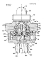
- - la figure 2 représente une vue schématique en coupe axiale, telle qu'illustrée par le plan de coupe référencé II-II sur la figure 3, d'un contacteur électrique conforme à une première variante de la présente invention définissant un contact ouvert au repos et fermé au travail,
- - la figure 3 représente une autre vue en coupe axiale du même contacteur, selon un plan de coupe orthogonal à celui de la figure 2 et illustré III-III sur cette figure 2,
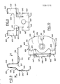
- - la figure 4 représente une vue axiale d'un support de borne, intégré au contacteur, selon une vue illustrée par la flèche référencée IV sur la figure 2,
- - la figure 5 représente une vue en coupe transversale partielle du contacteur selon un plan de coupe référencé V-V sur la figure 2,
- - la figure 6, qui correspond pour l'essentiel à une coupe axiale similaire à la figure 2 illustre schématiquement la phase d'étalonnage du contacteur, après l'assemblage, les demi-vues droite et gauche du contacteur illustrant deux phases successives du processus d'étalonnage,
- - la figure 7 représente une vue schématique en coupe axiale selon un plan de coupe similaire à celui de la figure 2 d'un contacteur conforme à une seconde variante de réalisation de la présente invention définissant un contact fermé au repos et ouvert au travail,
- - les figures 8, 9 et 10 représentent, selon trois vues orthogonales entre elles, une lamelle de contact intégrée au contacteur, les vues des figures 8 et 10 étant illustrées schématiquement sur la figure 9 sous forme des flèches référencées VIII et X,
- - la figure 11 représente une vue latérale, partiellement en coupe, telle qu'illustrée par le plan de coupe XI-XI sur la figure 13, d'un poussoir intégré dans un contacteur conforme à la première variante de réalisation précitée de la présente invention,
- - la figure 12 représente une autre vue latérale du même poussoir selon une vue orthogonale à celle de la figure 11,
- - la figure 13 représente une vue axiale du même poussoir selon une vue illustrée par la flèche référencée XIII sur la figure 11,
- - les figures 14 et 15 représentent deux vues respectivement orthogonales d'un autre poussoir destiné à être intégré au contacteur électrique conforme à la seconde variante de réalisation de la présente invention,
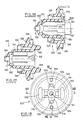
- - les figures 16 et 17 représentent deux vues en coupe axiale, respectivement orthogonales, et illustrées XVI-XVI et XVII-XVII sur la figure 18, d'un manchon guide intégré au contacteur électrique conforme à la présente invention,
- - la figure 18 représente une vue axiale du manchon guide, tel qu'illustré par la flèche référencée XVIII sur la figure 16,
- - la figure 19 représente une vue en coupe axiale, telle qu'illustrée par le plan de coupe référencé XIX-XIX sur la figure 20, d'un palpeur intégré dans un contacteur conforme à la présente invention, et
- - les figures 20 et 21 représentent deux vues axiales du même palpeur selon des vues illustrées XX et XXI sur la figure 19.
- - Figure 2 shows a schematic view in axial section, as illustrated by the cutting plane referenced II-II in Figure 3, of an electrical contactor according to a first variant of the present invention defining an open contact at rest and closed at work,
- FIG. 3 represents another view in axial section of the same contactor, according to a section plane orthogonal to that of FIG. 2 and illustrated III-III in this FIG. 2,
- FIG. 4 represents an axial view of a terminal support, integrated into the contactor, according to a view illustrated by the arrow referenced IV in FIG. 2,
- FIG. 5 represents a partial cross-sectional view of the contactor according to a cutting plane referenced VV in FIG. 2,
- - Figure 6, which essentially corresponds to an axial section similar to Figure 2 schematically illustrates the calibration phase of the contactor, after assembly, the right and left half-views of the contactor illustrating two successive phases of the process calibration,
- FIG. 7 represents a schematic view in axial section along a cutting plane similar to that of FIG. 2 of a contactor according to a second variant embodiment of the present invention defining a contact closed at rest and open at work,
- FIGS. 8, 9 and 10 represent, in three orthogonal views between them, a contact strip integrated in the contactor, the views of FIGS. 8 and 10 being illustrated diagrammatically in FIG. 9 in the form of arrows referenced VIII and X,
- - Figure 11 shows a side view, partially in section, as illustrated by the section plane XI-XI in Figure 13, of a pusher integrated in a contactor according to the aforementioned first embodiment of the present invention ,
- FIG. 12 represents another side view of the same pusher in a view orthogonal to that of FIG. 11,
- FIG. 13 represents an axial view of the same pusher according to a view illustrated by the arrow referenced XIII in FIG. 11,
- FIGS. 14 and 15 show two respectively orthogonal views of another pusher intended to be integrated into the electrical contactor according to the second variant embodiment of the present invention,
- FIGS. 16 and 17 represent two views in axial section, respectively orthogonal, and illustrated XVI-XVI and XVII-XVII in FIG. 18, of a guide sleeve integrated into the electrical contactor according to the present invention,
- FIG. 18 represents an axial view of the guide sleeve, as illustrated by the arrow referenced XVIII in FIG. 16,
- FIG. 19 represents a view in axial section, as illustrated by the cutting plane referenced XIX-XIX in FIG. 20, of a probe integrated in a contactor according to the present invention, and
- FIGS. 20 and 21 represent two axial views of the same probe according to illustrated views XX and XXI in FIG. 19.
Le contacteur électrique conforme à la présente invention illustré sur les figures annexées comprend pour l'essentiel un boîtier 100, un palpeur 200, un poussoir de commande 400, un manchon guide 500, deux lamelles de contact 600, 650 et deux plots 800, 820.The electrical contactor according to the present invention illustrated in the appended figures essentially comprises a
Le contacteur possède un axe de symétrie 112.The contactor has an axis of
Pour simplifier la description qui va suivre, on appellera "extrémité avant" du boîtier 100 l'extrémité de celui-ci par laquelle émerge le palpeur 200, et "extrémité arrière" du boîtier, l'extrémité de celui-ci par laquelle émergent les plots 800, 820.To simplify the description which follows, the end of the latter by which the
Le boîtier 100 possède une chambre interne 120 de révolution autour de l'axe 112. La chambre 120 est composée plus précisément, de préférence, de trois sections 122, 124 et 126, qui se succèdent axialement. Les sections 122, 124 et 126 ont des diamètres croissants de l'extrémité avant du boîtier vers l'extrémité arrière.The
Sur sa périphérie, le boîtier 100 est pourvu de deux portions filetées 130, 132, respectivement adjacentes à l'extrémité avant et à l'extrémité arrière. Entre les filetages 130, 132, le boîtier 100 est pourvu d'une zone intermédiaire 134 de section droite hexagonale ou équivalente pour permettre l'assemblage du boîtier par filetage dans un appareil associé.On its periphery, the
Le boîtier 100 possède en outre sur sa surface interne et au niveau de son extrémité avant une nervure annulaire 128. Cette nervure annulaire 128 est ménagée en saillie sur la surface interne de la section avant 122, en position adjacente à la surface avant 136 du boîtier,transversale à l'axe 112.The
La nervure 128 sert de butée au palpeur 200 comme illustré sur la figure 2.The
Le palpeur 200 est formé d'une pièce. Pour l'essentiel, il comprend une calotte semi-sphérique 210, qui se prolonge vers l'arrière par un cylindre 220 centré sur l'axe 112. La calotte 210 et le cylindre 220 définissent en combinaison une chambre 230 ouverte vers l'arrière.The
Le diamètre extérieur du cylindre 220 correspond avec un certain jeu au diamètre interne de la nervure 128. Par ailleurs, le cylindre 220 est muni,sur sa périphérie extérieure et en position adjacente à son extrémité arrière,d'une nervure annulaire 222. La nervure 222 possède un diamètre externe sensiblement égal au diamètre interne de la plus petite section 122 de la chambre 120 du boîtier et assure le guidage du palpeur 200.The external diameter of the
L'homme de l'art comprendra aisément à l'examen de la figure 2 annexée qu'ainsi le palpeur 200 peut être introduit dans la chambre 120 du boîtier 100, et émerger sur l'extrémité avant de celui-ci, le déplacement du palpeur 200 vers l'avant par rapport au boîtier 100 étant limité lorsque la nervure 222 vient reposer contre la nervure 128 du boîtier.A person skilled in the art will readily understand on examining the appended FIG. 2 that thus the
Pour éviter toute compression du fluide contenu dans la chambre 120 du boîtier lors du déplacement du palpeur 200, celui-ci est muni au niveau de la calotte hémisphérique 210 d'une pluralité d'ouvertures traversantes 212, 214, 216 équi-réparties autour de l'axe 112.To avoid any compression of the fluid contained in the
Par ailleurs, la calotte hémisphérique 210 est pourvue sur sa surface interne d'un fût 217 centré sur l'axe 112. Le fût 217 définit un logement interne 218 cylindrique centré sur l'axe 112 et ouvert vers l'arrière. Le logement 218 est destiné à recevoir comme illustré sur la figure 2 l'extrémité avant du poussoir 400.Furthermore, the
Le poussoir 400 possède pour l'essentiel un tronc 410 rectiligne et centré sur l'axe 112, prolongé vers l'arrière par deux paires de bras 420A, 420B d'une part, 430A, 430B d'autre part.The
Les bras 420, 430 s'étendent pour l'essentiel parallèlement à l'axe 112. Au niveau de chaque paire, les bras 420, 430 sont symétriques par rapport à l'axe 112.The
Les bras 420 sont destinés à coopérer avec les lamelles de contact 600, 650 pour modifier l'état de liaison de celles-ci. Les bras 430 sont destinés à guider le poussoir 400 lors de son coulissement.The
Les bras de commande 420 sont plus longs que les bras de guidage 430.The
La surface arrière des bras de guidage 430A, 430B, qui est transversale à l'axe 112 est référencée 432A, 432B. On notera que les bras de guidage 430 sont pourvus,sur leur surface extérieure 434, et en position adjacente à la surface arrière 432 précitée,d'évidements 436. Ces évidements 436 sont destinés à recevoir un embout 802, 822 ménagé sur les plots 800, 820 lorsque le poussoir est déplacé vers l'arrière contre une butée axiale solidaire du boîtier, lors de la phase d'étalonnage.The rear surface of the
Selon le premier mode de réalisation illustré sur les figures 11, 12 et 13, chaque bras de commande 420 est composé de deux toiles 421, 422 planes et allongées parallèlement à l'axe 112, qui se terminent vers l'arrière par un bloc 425. La toile 421 s'étend sensiblement radialement par rapport à l'axe 112.According to the first embodiment illustrated in FIGS. 11, 12 and 13, each
La toile 422 est solidaire de la toile 421. Elle est placée sur l'extérieur de celle-ci et s'étend transversalement à un rayon dressé à partir de l'axe 112.The
L'extrémité arrière des bras de commande 420, qui est définie par le bloc 425 est délimitée par deux surfaces latérales 423, 424. Les surfaces latérales 423, 424 sont définies par des génératrices transversales à l'axe 112. Les surfaces latérales 423, 424 convergent symétriquement vers l'arrière. Par ailleurs, comme cela apparaît à l'examen de la figure 11, le bloc 425 est délimité vers l'avant, en regard de la toile interne 421 par deux surfaces latérales 426, 427. Les surfaces 426, 427 sont délimitées par des génératrices transversales à l'axe 112. Les surfaces latérales 426, 427 convergent symétriquement vers l'avant.The rear end of the
On notera également à l'examen de la figure 11 annexée que le tronc 410 du poussoir 400 est pourvu sur son extrémité avant d'un fût 412 pourvu de cannelures longitudinales. Le fût 412 est destiné à pénétrer dans le logement 218 ménagé dans le palpeur 200 pour être maintenu sur celui-ci par friction.It will also be noted on examining the appended FIG. 11 that the
Le manchon guide 500 présente une symétrie par rapport à l'axe 112. Il comprend un fourreau principal 510 défini par une enveloppe généralement cylindrique centrée sur l'axe 112. Le fourreau 510 possède un logement interne 512. Ce logement 512 reçoit les bras de commande 420 et les bras de guidage 430. Le logement 512 possède une section droite en forme d'étoile à quatre branches, référencées 514, 516, 518 et 520 sur la figure 18. La section droite du logement 512 est complémentaire de l'enveloppe des bras de commande 420 et des bras de guidage 430. L'extrémité avant 522 du fourreau est munie d'une lèvre annulaire 524 qui converge en direction de l'axe 512, vers l'avant. La lèvre 524 est destinée à serrer de façon étanche le tronc cylindrique 410 du poussoir 400.The
Le fourreau principal 510 est par ailleurs pourvu, sur sa périphérie extérieure et au niveau de son extrémité arrière, d'un flasque 530 en forme générale de couronne transversale à l'axe 112. Le flasque 530 est adapté pour être pincé, au niveau de sa périphérie extérieure, entre le boîtier 100 et le bouchon 900 supportant les plots 800, 820. Plus précisément encore le flasque 530, comme illustré sur les figures, est pincé entre le décrochement 125 transversal à l'axe 112 défini sur le boîtier entre les sections 124, 126 du logement 120 d'une part, et le bouchon support 900 d'autre part.The
La flasque 530 porte sur la périphérie extérieure du fourreau principal 510 un joint à lèvre cylindrique 532. Le joint 532 est dirigé vers l'avant. Il est engagé dans la section 124 du logement 120 et adapté pour être plaqué contre la surface interne de la section 124.The
Lorsque le contacteur est utilisé dans un milieu de fluide sous pression, le fluide peut pénétrer dans le logement 120 par l'intermédiaire des ouvertures 212, 214 et 216 ménagées dans le palpeur 200. Ainsi, la pression du fluide, qui s'applique sur la périphérie interne 533 du joint cylindrique 532 tend à plaquer étroitement le joint 532 contre le surface 124 du logement 120.When the contactor is used in a medium of pressurized fluid, the fluid can penetrate into the
Par ailleurs, le flasque 530 est pourvu d'un second joint à lèvre cylindrique 534. Le joint 534 s'étend vers l'arrière. Il est destiné à être plaqué contre la surface avant conique du bouchon support 900.Furthermore, the
Le manchon guide 500 doit assurer un positionnement angulaire précis du poussoir 400 par rapport aux lamelles de contact 600, 650. De ce fait, le manchon 500 doit être positionné angulairement avec précision par rapport au bouchon support 900. Le positionnement angulaire du manchon 500 est défini d'une part par deux tétons 540, 542 en saillie sur la surface arrière du flasque 530, d'autre part par deux logements 544, 546 ménagés également sur la surface arrière du flasque 530.The
Les tétons 540, 542 sont diamètralement opposés et destinés à pénétrer dans des chambres complémentaires ménagées dans le bouchon support 900.The
Les logements 544, 546 sont également diamètralement opposés et décalés angulairement de 90° par rapport aux tétons 540, 542 précités.The
Les logements 544, 546 sont engagés sur des nervures 902, 904, diamètralement opposées, ménagées sur le bouchon support 900.The
On notera que le manchon guide 500 est en outre pourvu, sur la surface arrière du flasque 530 de deux autres logements 550, 552 diamètralement opposés qui reçoivent les embouts 802, 822 des plots de contact.It will be noted that the
Enfin, on notera à l'examen des figures annexées que le manchon guide 500 définit, sur sa périphérie extérieure et en position adjacente à son extrémité avant, un niveau de la zone de liaison entre le fourreau principal 510 et le joint 524, une surface 560 en forme de couronne transversale à l'axe 112. Cette surface 560 est dirigée vers l'avant et est destinée à servir de butée axiale limitant le déplacement du palpeur 200 vers l'intérieur du boîtier 100,lors de la phase d'étalonnage initial.Finally, it will be noted on examining the appended figures that the
Le contacteur électrique conforme à la présente invention illustré sur les figures annexées comprend deux lamelles 600, 650, identiques. Ces lamelles présentent une symétrie par rapport à un plan passant par l'axe 112. On va maintenant décrire la struc ture de la lamelle 600 en regard des figures 8, 9 et 10 annexées.The electrical contactor according to the present invention illustrated in the appended figures comprises two
Pour l'essentiel, la lamelle 600 comprend une plaque de fixation 610, deux ailes élastiques 620, 630 en forme de "U", et une palette de contact 640.Essentially, the
La plaque de fixation 610 s'étend perpendiculairement à l'axe 112. Elle est pourvue d'une ouverture cylindrique 612 définie au niveau d'un collet 614 de forme tronconique réalisé par déformation de la plaque 610. Le collet 614 s'étend vers l'avant par rapport à la plaque de fixation 610. Le diamètre de l'ouverture 612 est complémentaire du diamètre des embouts 802, 822 ménagés sur l'extrémité avant des plots 800, 820. Ainsi, les collets 614 peuvent être chassés sur les embouts 802, 822 pour assurer une liaison électrique fiable entre les lamelles électriquement conductrices 600, 650 et les plots 800, 820.The fixing
De plus, la plaque de fixation 610 est pourvue sur son bord extérieur 615 d'une découpe 616 adaptée pour recevoir les nervures 902, 904 prévues sur le bouchon support 900. La coopération ainsi définie entre les nervures 902, 904 et les découpes 616 assure une immobilisation à rotation des lamelles 600, 650 sur le bouchon support 900, et donc un positionnement précis des lamelles.In addition, the fixing
Les ailes élastiques 620, 630 se raccordent au bord interne de la plaque de fixation 610 au voisinage de ses bords latéraux 618, 619.The
Chacune des ailes élastiques 620, 630 est composée de deux branches 621, 622 , d'une part, et 631, 632 d'autre part. Les branches 621, 631 s'étendent vers l'arrière, sensiblement parallèlement à l'axe 112. Les ailes 622, 632 s'étendent vers l'avant, sensiblement parallèlement à l'axe 112. Les branches 621, 622 d'une part, 631, 632 d'autre part, se raccordent par une portion incurvée 623, 633.Each of the
La palette de contact 640 a la forme générale d'un "I" composé d'une âme centrale 641 et de deux traverses 643, 644 qui seront respectivement dénommées par la suite arrière et avant compte tenu de leur positionnement dans le contacteur.The
La traverse arrière 643 s'étend transversalement à l'axe 112 et relie les deux branches 622, 632. On notera par ailleurs à l'examen de la figure 9 qu'elle converge en direction de l'axe 112 en rapprochement de l'âme centrale 641, soit vers l'avant.The
L'âme centrale 641 s'étend sensiblement parallèlement à l'axe 112.The
La traverse avant 644 s'étend pour l'essentiel transversalement à l'axe 112. Elle est pourvue d'un plot de contact central 642. Les deux plots 642 portés respectivement par les lamelles 600, 650 sont destinés à venir en contact. Les axes des plots 642 sont transversaux à l'axe 112 du boîtier et sécants de cet axe. La séparation des plots 642 est opérée par le poussoir 400, lorsque l'extrémité arrière de celui-ci écarte les palettes de contact 640. Pour faciliter le déplacement de l'extrémité arrière du poussoir 400 entre les palettes de contact 640, le bord libre avant 645 de la traverse avant 644 est incurvé vers l'extérieur. De même les bords libres arrière 646, 647 de la traverse avant 644, sont placés res pectivement de part et d'autre de l'âme centrale 641, sont inclinés vers l'extérieur.The
Le ressort de rappel 700 est un ressort hélicoïdal. Il est engagé entre le palpeur 200 et le manchon guide 500. Plus précisément, l'extrémité arrière du ressort de rappel 700 est engagée entre la périphérie extérieure du fourreau principal 510 et la périphérie intérieure du joint cylindrique 532. Le ressort de rappel 700 repose contre la surface avant du flasque 530.The
Le bouchon support 900 est moulé sur les deux plots conducteurs 800, 820. On notera que seuls ces plots 800, 820 et les lamelles de contact 600, 650 sont réalisés en matériau électriquement conducteur. Les autres éléments, boîtier 100, palpeur 200, poussoir 400, manchon guide 500 et bouchon support 900 sont réalisés en matériau électriquement isolant.The
Les plots 800, 820 sont formés de corps généralement cylindriques dont les axes 804, 824 sont parallèles à l'axe 112 et diamètralement opposés par rapport à celui-ci. Les plots 800, 820 sont munis sur leur périphérie extérieure de nervures annulaires 805, 806, 825, 826 définissant une liaison rigide entre les plots 800, 820 et le bouchon obturateur 900, notamment en interdisant tout déplacement à translation des plots 800, 820 par rapport au bouchon support 900.The
Les plots 800, 820 émergent largement sur la surface arrière 906 du bouchon support 900.The
Sur leur extémité avant, émergeant du support 900, les plots 800, 820 sont pourvus d'embouts 802, 822 d'enveloppe cylindrique, de plus faible section, centrés sur les axes 804, 824.On their front end, emerging from the
Les embouts 802, 822 sont engagés dans les collets 614 pour assurer une liaison électrique entre les plots 800, 820 et les lamelles 600, 650 respectivement associés. Le bouchon support 900 a la forme générale d'un disque. Il est fixé sur le boîtier 100 dans la section 126 du logement 120 par tout moyen approprié, par exemple par sertissage, soudure, vissage ou équivalent.The ends 802, 822 are engaged in the
Le bouchon support 900 est pourvu d'une chambre 910 centrée sur l'axe 112 et débouchant sur sa surface avant. Cette chambre 910 est destinée à recevoir les lamelles de contact 600, 650 en assurant un libre fléchissement des ailes élastiques 620, 630, ainsi que l'extrémité arrière du poussoir 400.The
Les deux nervures 902, 904 précitées engagées d'une part dans les ouvertures 616 des lamelles de contact, d'autre part dans les logements 544, 546 du manchon guide 500 font saillie sur la périphérie interne de la chambre 910. Elles s'étendent sensiblement parallèlement à l'axe 112 et sont diamètralement opposées par rapport à celui-ci.The two
Pour assembler le contacteur électrique comprenant les éléments précités on procède comme suit.To assemble the electrical contactor comprising the aforementioned elements, the procedure is as follows.
On engage successivement dans le boîtier 100, par l'extrémité arrière de celui-ci, le palpeur 200, le ressort 700, le manchon 500, le poussoir 400 puis le bouchon support 900 équipé de plots de contact 800, 820 et des deux lamelles associées 600, 650.Is engaged successively in the
Comme indiqué précédemment le joint cylindrique 524 assure l'étanchéité sur la périphérie du poussoir 400 traversant le manchon 500. Par ailleurs, les joints cylindriques 532, 534 assurent l'étanchéité entre le boîtier 100 et le bouchon support 900. Ainsi, les joints 524, 532, 534 isolent efficacement les lamelles de contact 600, 650 et les plots 800, 820 du fluide sous pression dans lequel baigne le palpeur 200.As indicated above, the
Le ressort de rappel 700 pousse le palpeur 200 contre la nervure avant 128.The
Les lamelles 600 et 650 sont pincées au niveau de la plaque de fixation 610 entre la face arrière du manchon 500 et la face avant des bornes 800 et 820 pour permettre le rattrapage de jeu et obtenir un positionnement précis et stable des lamelles 600 et 650.The
Après cet assemblage, le fût avant 412 du poussoir 400 ne pénètre que faiblement dans le logement associé 218 du palpeur 200. La position initiale des éléments est illustrée sur la demi- vue droite de la figure 6.After this assembly, the
Pour positionner axialement avec précision le poussoir 400, par rapport au palpeur 200 et par rapport aux lamelles de contact 600, 650, afin d'obtenir un fonctionnement correct du contacteur lors du déplacement du palpeur 200, comme illustré schématiquement sur la demi vue gauche de la figure 6, on déplace le palpeur 200 au maximum vers l'intérieur du boîtier 100. Lors de ce déplacement du palpeur 200, le poussoir 400 est sollicité vers l'intérieur du boîtier 100. Le déplacement du poussoir 400 est limité lorsque les surfaces arrière 432 des bras de guidage 430 viennent reposer contre les plaques de fixation 610 comme illustré sur la gauche de la figure 6. De même, le déplacement du palpeur 200 est interrompu lorsque la surface arrière 224 de celui-ci vient reposer contre la surface d'appui 560 du bouchon guide 500.To position the
Au cours de ses déplacements, le fût 412 avant du poussoir 400 pénètre à force dans le logement complémentaire 218 du palpeur 200. Le poussoir 400 est ainsi immobilisé par rapport au palpeur 200. Sa position relative est obtenue avec précision grâce à l'appui défini, d'une part, entre le palpeur 200 et le manchon guide 500, d'autre part, entre le poussoir 400 lui-même et les plaques de fixation 610.During its movements, the
On va maintenant décrire le fonctionnement du contacteur électrique illustré sur les figures 2 et 3 annexées.We will now describe the operation of the electrical contactor illustrated in Figures 2 and 3 attached.
Au repos, le ressort de rappel 700 sollicite le palpeur 200 vers l'avant contre la nervure 128.At rest, the
La partie de plus grand évasement des blocs 425 prévus à l'extrémité arrière des bras de commande 420 est placée entre les traverses avant 644 des palettes de contact 640 des lamelles 600, 650, comme illustré sur la figure 2.The widest part of the
Le plus grand évasement précité des blocs 425 est référencé L sur la figure 11. Il est défini entre la zone 428 de liaison entre les surfaces 423, 426 d'une part, et la zone 429 de liaison entre les surfaces 424, 427 d'autre part.The aforementioned largest widening of the
Le grand évasement L précité des blocs 425 est supérieur au double de l'épaisseur des plots 642 portés par les lamelles de contact 600, 650. Ainsi, lorsque le grand évasement L des blocs 425 est placé entre les traverses avant 644, 640, les deux plots de contact 642 sont séparés. L'interrupteur formé entre les plots 800, 820 est donc ouvert.The aforementioned large flaring L of the
Par contre, lorsque sous l'effet d'une force extérieure le palpeur 200 recule vers l'intérieur du logement 120, le poussoir 400 étant simultané ment déplacé vers l'arrière parallèlement à l'axe 112, le bloc 425 prévu à l'extrémité arrière des bras de commande 420 passe au-delà, vers l'arrière, de la traverse avant 644 des palettes de contact 640. On notera que les toiles 422 des bras de commande 420 sont placées vers l'extérieur de la traverse avant 644. Ainsi, lorsque le poussoir 400 est déplacé vers l'arrière en position de travail, seule la toile 421 interne est placée entre les traverses 644 des palettes de contact 640. La largeur 1 des toiles 421 est inférieure au double de l'épaisseur des grains de contact 642. Ainsi, les grains de contact 642 sont sollicités élastiquement en contact mutuel par les ailes élastiques 620, 630. La liaison électrique entre les plots 800, 820 est alors fermée.On the other hand, when under the effect of an external force the
Lorsque la force exercée sur le palpeur 200 est relâchée, le ressort de rappel 700 repousse le palpeur 200 et le poussoir 400 qui lui est lié par l'intermédiaire du fût 412, vers l'avant, en appui contre la nervure 128. Les blocs 425 sont ainsi ramenés entre les traverses 644 des palettes de contact 640, pour séparer à nouveau les grains de contact 642.When the force exerted on the
Les deux blocs 425 prévus en extrémité arrière des bras de commande 420, en forme de fourche, se déplacent contre les surfaces en regard des palettes de contact 640, de part et d'autre des plots 642, sans jamais venir en contact avec les plots. Ainsi les blocs 425 ne risquent pas de polluer les plots 642 par dépôt de matière sur ceux-ci.The two
Comme indiqué précédemment, les bords 645, 646 et 647 incurvés vers l'extérieur des palettes de contact 640 facilitent le déplacement des blocs 425 entre les palettes 640. On notera que la modification de l'état élec trique du contacteur est opérée par déplacement des palettes de contact 640, transversalement à l'axe 112, grâce à l'élasticité des ailes 620, 630. Grâce à cette disposition, il n'est pas nécessaire de prévoir un ressort de surcourse dans le contacteur. En effet un déplacement du palpeur 200 et du poussoir 400, supérieure à la normale, ne peut en aucune façon détériorer les lamelles 600, 650.As indicated previously, the
Le contacteur qui vient d'être décrit correspond à un état de contact ouvert au repos et fermé au travail.The contactor which has just been described corresponds to a contact state open at rest and closed at work.
Ce contacteur peut aisément être adapté pour définir un état de contact fermé au repos et ouvert au travail en remplaçant le poussoir 400 précédemment décrit et illustré sur les figures 11, 12 et 13 par le poussoir 400ʹ illustré sur les figures 14 et 15.This contactor can easily be adapted to define a state of contact closed at rest and open to work by replacing the
Le poussoir 400ʹ illustré sur les figures 14 et 15 comprend également un tronc 410ʹ centré sur l'axe 112, une paire de bras de commande 420ʹA, 420ʹB et une paire de bras de guidage 430ʹA, 430ʹB. Les bras de guidage 430ʹ sont identiques aux bras de guidage 430 précités et ne seront donc pas décrits plus en détail par la suite.The pusher 400ʹ illustrated in FIGS. 14 and 15 also comprises a trunk 410ʹ centered on the
Les bras de commande 420ʹA, 420ʹB sont plus courts que les bras 420 précités.The control arms 420ʹA, 420ʹB are shorter than the
Les bras de commande 420ʹ sont formés de tige rectiligne s'étendant parallèlement à l'axe 112. Ces tiges 420ʹ ont une largeur L constante correspondant au plus grand évasement L des blocs 425 précités.The control arms 420ʹ are formed of a straight rod extending parallel to the
L'extrémité arrière des bras de commande 420ʹ est effilée. Elle est définie par deux surfaces latérales 423ʹ, 424ʹ, qui convergent symétriquement vers l'arrière.The rear end of the 420ʹ control arms is tapered. It is defined by two lateral surfaces 423ʹ, 424ʹ, which converge symmetrically towards the rear.
La longueur des bras de commande 420ʹ est adaptée de telle sorte qu'en position de repos, lorsque le palpeur 200 est repoussé contre la nervure 128 par le ressort de rappel 700, les surfaces d'extrémité 423ʹ, 424ʹ des bras de commande 420ʹ soient placés en avant des traverses 644. Ainsi, les plots 642 sont sollicités élastiquement en contact. Par contre, lorsque le palpeur 200 et le poussoir 400ʹ associé sont déplacés vers l'arrière, les bras de commande 420ʹ pénètrent entre les traverses 644 pour séparer les plots de contact 642.The length of the control arms 420ʹ is adapted so that in the rest position, when the
Là encore, lorsque l'effort exercé sur le palpeur 200 est relâché, le ressort 700 repousse le palpeur 200 et le poussoir 400ʹ associé vers l'avant pour autoriser à nouveau la mise en contact des grains 642.Here again, when the force exerted on the
L'homme de l'art comprendra aisément que les poussoirs 400 peuvent en outre être adaptés pour définir différents états successifs des contacts lors du déplacement du palpeur 200.Those skilled in the art will readily understand that the
Ainsi, par exemple, le poussoir 400 illustré sur les figures 11, 12 et 13 pourrait être équipé de deux blocs 425 espacés longitudinalement pour définir successivement, une position de repos à contact ouvert, lorsque le bloc 425 le plus arrière est placé entre les traverses 644, une première position de travail à contact fermé, lorsque les toiles 421 sont placées entre les traverses 644 et enfin une deuxième position de travail à contact ouvert lorsque le bloc 425 le plus avant est placé entre les traverses 644.Thus, for example, the
De préférence, et à titre d'exemple non limitatif :
- le palpeur 200 est réalisé en polyamide chargé 30% fibres de verre et 15% en polysulfone de phénylène,
- le poussoir 400 est réalisé en polyamide, et
- le manchon guide 500 est réalisé en polytéréphtalate d'éthylène souple 55 shore.Preferably, and by way of nonlimiting example:
- the
the
- the
Bien entendu la présente invention n'est pas limitée aux exemples de réalisation qui viennent d'être décrits mais s'étend à toute variante conforme à son esprit.Of course the present invention is not limited to the embodiments which have just been described but extends to any variant in accordance with its spirit.
On notera que le contacteur conforme à l'invention possède un faible nombre de pièces. Que par ailleurs, mis à part le poussoir 400, l'ensemble des pièces composant le contacteur est commun aux deux variantes, ouvert au repos et fermé au repos. Le contacteur est totalement insensible aux fluctuations de pression. Il définit une isolation certaine entre le fluide et les contacts électriques. Par ailleurs, le contacteur conforme à l'invention n'exige pas de ressort de surcourse.Note that the contactor according to the invention has a small number of parts. That moreover, apart from the
Les éléments formant joint annulaire à lèvre 524, 532 et 534 prévus sur le manchon 500 présentent une faible épaisseur radiale, pour être souples et s'appliquer élastiquement respectivement contre le corps 410 du poussoir 400, la surface interne 124 du boîtier et la surface avant du bouchon 900.The elements forming an
Par contre, lorsque le manchon 500 sert de butée au palpeur 200 au niveau de sa surface 560, il travaille dans le sens axial, c'est-à-dire dans le sens de sa plus grande épaisseur et est de ce fait rigide pour limiter avec précision le déplacement du palpeur 200.On the other hand, when the
Claims (15)
- un boîtier (100) qui porte
- une paire de lamelles de contact en matériau électriquement conducteur (600, 650) pourvues de plaquettes de contact (640) portant des plots (642) aptes à venir en contact,
- un palpeur (200) émergeant à l'extérieur du boîtier (100), et susceptible de coulissement parallèlement à l'axe (112) du boîtier,
- un poussoir (400) solidaire du palpeur (200) pour être déplacé à coulissement, parallèlement à l'axe (112) du boîtier, entre une position de repos et une position de travail, et ainsi venir s'intercaler sélectivement entre les plaquettes de contact (640) afin de déplacer celles-ci transversalement à l'axe (112) du boîtier pour modifier l'état de liaison des plots (642),
- un manchon (500) traversé par le poussoir (400) qui guide le poussoir (400) à coulissement parallèlement à l'axe (112) du boîtier et assure une séparation étanche entre le milieu contenant l'organe actif susceptible d'agir sur le contacteur et les contacts électriques (600, 650), et
- un ressort (700) intercalé entre le manchon (500) et le palpeur (200) pour solliciter le palpeur (200) et le poussoir (400) vers la position de repos. 15. Electric contactor according to one of claims 1 to 14, characterized in that it comprises:
- a housing (100) which carries
- a pair of contact strips of electrically conductive material (600, 650) provided with contact plates (640) carrying pads (642) capable of coming into contact,
- a probe (200) emerging outside the housing (100), and capable of sliding parallel to the axis (112) of the housing,
- A pusher (400) integral with the feeler (200) to be moved to slide, parallel to the axis (112) of the housing, between a rest position and a working position, and thus selectively interpose between the pads contact (640) in order to move these transversely to the axis (112) of the housing to modify the state of connection of the studs (642),
- A sleeve (500) crossed by the pusher (400) which guides the pusher (400) sliding parallel to the axis (112) of the housing and ensures a sealed separation between the medium containing the active member capable of acting on the contactor and the electrical contacts (600, 650), and
- A spring (700) interposed between the sleeve (500) and the probe (200) to urge the probe (200) and the pusher (400) towards the rest position.
Applications Claiming Priority (2)
| Application Number | Priority Date | Filing Date | Title |
|---|---|---|---|
| FR8704288 | 1987-03-27 | ||
| FR8704288A FR2613119A1 (en) | 1987-03-27 | 1987-03-27 | ELECTRICAL POSITION SWITCH |
Publications (2)
| Publication Number | Publication Date |
|---|---|
| EP0284515A1 true EP0284515A1 (en) | 1988-09-28 |
| EP0284515B1 EP0284515B1 (en) | 1992-06-10 |
Family
ID=9349496
Family Applications (1)
| Application Number | Title | Priority Date | Filing Date |
|---|---|---|---|
| EP19880400722 Expired - Lifetime EP0284515B1 (en) | 1987-03-27 | 1988-03-24 | Electrical position switch |
Country Status (3)
| Country | Link |
|---|---|
| EP (1) | EP0284515B1 (en) |
| DE (1) | DE3871837T2 (en) |
| FR (1) | FR2613119A1 (en) |
Families Citing this family (1)
| Publication number | Priority date | Publication date | Assignee | Title |
|---|---|---|---|---|
| DE19808060A1 (en) * | 1998-02-26 | 1999-09-09 | Euchner Gmbh & Co | Limit switch |
Citations (5)
| Publication number | Priority date | Publication date | Assignee | Title |
|---|---|---|---|---|
| US2239426A (en) * | 1939-04-19 | 1941-04-22 | Gen Electric | Electric switch |
| US2753413A (en) * | 1953-09-28 | 1956-07-03 | Airtron Inc | Quick break electric switches |
| DE1123732B (en) * | 1960-01-07 | 1962-02-15 | Standard Elektrik Lorenz Ag | Push button or push button switch, especially for telecommunications systems, with a member influencing the switching sequence |
| EP0028000A1 (en) * | 1979-10-30 | 1981-05-06 | Siemens Aktiengesellschaft | Push-button switch |
| EP0043618A1 (en) * | 1980-07-08 | 1982-01-13 | Philips Electronics Uk Limited | Push button switch |
-
1987
- 1987-03-27 FR FR8704288A patent/FR2613119A1/en active Pending
-
1988
- 1988-03-24 EP EP19880400722 patent/EP0284515B1/en not_active Expired - Lifetime
- 1988-03-24 DE DE19883871837 patent/DE3871837T2/en not_active Expired - Lifetime
Patent Citations (5)
| Publication number | Priority date | Publication date | Assignee | Title |
|---|---|---|---|---|
| US2239426A (en) * | 1939-04-19 | 1941-04-22 | Gen Electric | Electric switch |
| US2753413A (en) * | 1953-09-28 | 1956-07-03 | Airtron Inc | Quick break electric switches |
| DE1123732B (en) * | 1960-01-07 | 1962-02-15 | Standard Elektrik Lorenz Ag | Push button or push button switch, especially for telecommunications systems, with a member influencing the switching sequence |
| EP0028000A1 (en) * | 1979-10-30 | 1981-05-06 | Siemens Aktiengesellschaft | Push-button switch |
| EP0043618A1 (en) * | 1980-07-08 | 1982-01-13 | Philips Electronics Uk Limited | Push button switch |
Also Published As
| Publication number | Publication date |
|---|---|
| FR2613119A1 (en) | 1988-09-30 |
| DE3871837T2 (en) | 1992-12-03 |
| DE3871837D1 (en) | 1992-07-16 |
| EP0284515B1 (en) | 1992-06-10 |
Similar Documents
| Publication | Publication Date | Title |
|---|---|---|
| FR2758662A1 (en) | MOBILE CONTACT COAXIAL ELECTRIC CONNECTOR ELEMENT AND COAXIAL ELECTRIC CONNECTOR INCLUDING SUCH A CONNECTOR ELEMENT | |
| EP0050575A1 (en) | Fast locking-unlocking electrical connector | |
| FR2781934A1 (en) | COAXIAL CONNECTOR ELEMENT HAVING A CONNECTION FOR CONNECTING THE CENTRAL CONDUCTOR OF A COAXIAL CABLE TO THE CENTRAL CONTACT OF THE CONNECTOR ELEMENT | |
| EP0491626A1 (en) | Electrical coaxial connector | |
| CA1329420C (en) | Electric connector | |
| FR2624313A1 (en) | ||
| FR2760137A1 (en) | COAXIAL ELECTRICAL CONNECTOR | |
| EP0157666A1 (en) | Rotating potentiometer, particularly for angular position measurement | |
| FR2901066A1 (en) | COAXIAL CONNECTOR | |
| FR2654268A1 (en) | CABLE ENTRY SEALING DEVICE IN A MULTICONTACT ALVEOLIC CONNECTOR ELEMENT. | |
| EP0284515B1 (en) | Electrical position switch | |
| EP0500466B1 (en) | Shutting device for the contact cavity of an electrical or optical connector | |
| EP0633629B1 (en) | Connection system | |
| FR2466093A1 (en) | THERMAL RUPTEUR | |
| EP2143174A1 (en) | Accessory of the backshell type for connector | |
| FR2644928A1 (en) | CONTROLLER IN PARTICULAR FOR MOTOR VEHICLES COMPRISING TWO ROTATING RINGS | |
| EP0084488A1 (en) | Wheel axle and extension piece for its production | |
| FR2579837A1 (en) | Cable grip for electrical installations | |
| EP0775916A1 (en) | Device for testing electrical connectors | |
| FR2681733A1 (en) | FEMALE CONTACT WITH ELASTIC PALLET AND PALLET FOR SUCH A CONTACT. | |
| FR2717003A1 (en) | Switching device for opening and closing a power line | |
| FR2707719A1 (en) | End piece for wear indicator of friction lining, in particular of brake pad. | |
| EP0121637B1 (en) | Straight electrical connecting end piece | |
| FR2545657A1 (en) | Improvements to safety devices for electrical connection, which can be used in particular as power outlets (sockets) | |
| FR2514552A1 (en) | ROTARY SWITCH WITH MULTIPLE POSITIONS |
Legal Events
| Date | Code | Title | Description |
|---|---|---|---|
| PUAI | Public reference made under article 153(3) epc to a published international application that has entered the european phase |
Free format text: ORIGINAL CODE: 0009012 |
|
| AK | Designated contracting states |
Kind code of ref document: A1 Designated state(s): DE ES FR GB IT |
|
| 17P | Request for examination filed |
Effective date: 19881121 |
|
| 17Q | First examination report despatched |
Effective date: 19910618 |
|
| GRAA | (expected) grant |
Free format text: ORIGINAL CODE: 0009210 |
|
| AK | Designated contracting states |
Kind code of ref document: B1 Designated state(s): DE ES FR GB IT |
|
| PG25 | Lapsed in a contracting state [announced via postgrant information from national office to epo] |
Ref country code: GB Effective date: 19920610 Ref country code: ES Free format text: THE PATENT HAS BEEN ANNULLED BY A DECISION OF A NATIONAL AUTHORITY Effective date: 19920610 |
|
| REF | Corresponds to: |
Ref document number: 3871837 Country of ref document: DE Date of ref document: 19920716 |
|
| ITF | It: translation for a ep patent filed |
Owner name: SOCIETA' ITALIANA BREVETTI S.P.A. |
|
| GBV | Gb: ep patent (uk) treated as always having been void in accordance with gb section 77(7)/1977 [no translation filed] | ||
| PLBE | No opposition filed within time limit |
Free format text: ORIGINAL CODE: 0009261 |
|
| STAA | Information on the status of an ep patent application or granted ep patent |
Free format text: STATUS: NO OPPOSITION FILED WITHIN TIME LIMIT |
|
| 26N | No opposition filed | ||
| PGFP | Annual fee paid to national office [announced via postgrant information from national office to epo] |
Ref country code: FR Payment date: 19940228 Year of fee payment: 7 |
|
| PGFP | Annual fee paid to national office [announced via postgrant information from national office to epo] |
Ref country code: DE Payment date: 19940326 Year of fee payment: 7 |
|
| PG25 | Lapsed in a contracting state [announced via postgrant information from national office to epo] |
Ref country code: FR Free format text: LAPSE BECAUSE OF NON-PAYMENT OF DUE FEES Effective date: 19951130 |
|
| PG25 | Lapsed in a contracting state [announced via postgrant information from national office to epo] |
Ref country code: DE Effective date: 19951201 |
|
| REG | Reference to a national code |
Ref country code: FR Ref legal event code: ST |
|
| PG25 | Lapsed in a contracting state [announced via postgrant information from national office to epo] |
Ref country code: IT Free format text: LAPSE BECAUSE OF NON-PAYMENT OF DUE FEES;WARNING: LAPSES OF ITALIAN PATENTS WITH EFFECTIVE DATE BEFORE 2007 MAY HAVE OCCURRED AT ANY TIME BEFORE 2007. THE CORRECT EFFECTIVE DATE MAY BE DIFFERENT FROM THE ONE RECORDED. Effective date: 20050324 |