EP0284508A2 - Drehmomentmesser - Google Patents
Drehmomentmesser Download PDFInfo
- Publication number
- EP0284508A2 EP0284508A2 EP88400681A EP88400681A EP0284508A2 EP 0284508 A2 EP0284508 A2 EP 0284508A2 EP 88400681 A EP88400681 A EP 88400681A EP 88400681 A EP88400681 A EP 88400681A EP 0284508 A2 EP0284508 A2 EP 0284508A2
- Authority
- EP
- European Patent Office
- Prior art keywords
- torque
- torsion shaft
- output signals
- signal
- detecting means
- Prior art date
- Legal status (The legal status is an assumption and is not a legal conclusion. Google has not performed a legal analysis and makes no representation as to the accuracy of the status listed.)
- Withdrawn
Links
- 230000000737 periodic effect Effects 0.000 claims abstract description 20
- 230000010363 phase shift Effects 0.000 claims description 18
- 230000005355 Hall effect Effects 0.000 claims description 3
- 238000001914 filtration Methods 0.000 claims description 2
- 238000001514 detection method Methods 0.000 abstract 1
- 230000008878 coupling Effects 0.000 description 12
- 238000010168 coupling process Methods 0.000 description 12
- 238000005859 coupling reaction Methods 0.000 description 12
- 238000002485 combustion reaction Methods 0.000 description 2
- 229910000831 Steel Inorganic materials 0.000 description 1
- 230000002238 attenuated effect Effects 0.000 description 1
- 230000005540 biological transmission Effects 0.000 description 1
- 239000003990 capacitor Substances 0.000 description 1
- 238000005352 clarification Methods 0.000 description 1
- 238000010276 construction Methods 0.000 description 1
- 239000013013 elastic material Substances 0.000 description 1
- 238000005259 measurement Methods 0.000 description 1
- 238000000034 method Methods 0.000 description 1
- 230000001105 regulatory effect Effects 0.000 description 1
- 239000010959 steel Substances 0.000 description 1
Images

Classifications
-
- G—PHYSICS
- G01—MEASURING; TESTING
- G01L—MEASURING FORCE, STRESS, TORQUE, WORK, MECHANICAL POWER, MECHANICAL EFFICIENCY, OR FLUID PRESSURE
- G01L3/00—Measuring torque, work, mechanical power, or mechanical efficiency, in general
- G01L3/02—Rotary-transmission dynamometers
- G01L3/04—Rotary-transmission dynamometers wherein the torque-transmitting element comprises a torsionally-flexible shaft
- G01L3/10—Rotary-transmission dynamometers wherein the torque-transmitting element comprises a torsionally-flexible shaft involving electric or magnetic means for indicating
- G01L3/109—Rotary-transmission dynamometers wherein the torque-transmitting element comprises a torsionally-flexible shaft involving electric or magnetic means for indicating involving measuring phase difference of two signals or pulse trains
Definitions
- the present invention relates to measuring devices and refers more specifically to an apparatus for detecting torque transmitted between the rotor of a prime mover and the rotor of a load, used in conjunction with signal processing devices to measure the torque.
- a prime mover such as an electric motor, an internal combustion engine or the like
- a rotary machine acting as a load are well known and widely used either for educational purposes or to provide torque information to a control system regulating the operation of the prime mover.
- the United States Patent 3 871 215 to PRATT, Jr et al, granted on March 18, 1975 discloses a torque measuring device wherein the twist angle of a shaft is obtained by using a light modulation scheme, the modulated light providing electric signals from which the torque information is derived.
- United States Patent 3 935 733 to SCHINDLER issued on February 3, 1976 relates to another type of torque measuring device in which the twist angle of a shaft is measured on the basis of the phase difference between two periodic signals recorded on magnetic tapes mounted on the twistable shaft at axially spaced locations thereon.
- the present invention is an improvement over the existing torque detectors and torque measuring device.
- the torque detector comprises a thin and flexible shaft which has one end adapted to be connected in driving relationship with the rotor of a prime mover, such as a motor, and has an opposite end adapted to be operatively connected to the rotor of a load, driven by the prime mover, the flexible shaft acting as a transmission shaft between the two rotors.
- a prime mover such as a motor
- the torque detector also includes a pair of recording mediums, such as magnetic tapes which are mounted to the flexible shaft at axially spaced locations thereon.
- each magnetic tape is mounted on the periphery of a collar which is attached at a respective end of the flexible shaft.
- a periodic signal such as a sinusoidal signal, is permanently recorded on each magnetic tape.
- a pair of reading heads are mounted adjacent the periphery of one of the collars to detect the periodic signal and generate two independent output signals.
- a single reading head is used to detect the periodic signal recorded on the magnetic tape mounted on the other collar.
- the twist angle in the flexible shaft which is proportional to the torque will produce a phase difference between the periodic signals recorded on the two magnetic tapes.
- the phase difference may be evaluated and the torque information may be derived.
- the torque detector is operatively connected to a microcomputer to form a torque measuring device.
- the task of the microcomputer is to process the output signals from the reading heads to calculate the phase shift between the signals and thus, determine the value of the torque.
- the two reading heads arrangement for detecting the periodic signal associated with one of the collars allows to determine the direction of rotation of the rotors. Whether one of the output signals lags or leads the other signal permits to determine if the rotors turn in a clockwise or a counterclockwise direction.
- This feature renders the torque measuring device simple and easy to use, leaving the task to the microcomputer to determine the magnitude of the torque applied as well as which one of the rotors supplies the power, according to the twist angle and the direction of rotation.
- the output signals generated by the reading heads are filtered by a high pass filter prior being fed to the microcomputer.
- This arrangement improves the accuracy of the torque measuring device in that it stabilizes the output signals from the reading heads as it will be explained in details in the description of a preferred embodiment given hereinafter.
- the present invention comprises in a general aspect a device for detecting torque, comprising: - a supporting structure; - a torsion shaft rotatably mounted to the supporting structure, the torsion shaft being adapted to transmit the torque to be detected, the torque producing a twist in the torsion shaft; - a first and a second recording mediums mounted at axially spaced locations on the torsion shaft, a periodic signal being recorded on the first and second recording mediums; - a first and a second signal detecting means mounted to the supporting structure and associated respectively with the first and second recording mediums for detecting the periodic signals and generating in turn output signals, the first signal detecting means including a pair of spaced apart sensors each adapted to detect the periodic signal recorded on the first recording medium and generate in turn an output signal, the twist producing a phase shift between the output signals of the first and second signal detecting means, the phase shift being representative of the torque, the first and second signal detecting means being adapted to be operatively connected to electronic means for processing the output signals generated
- the present invention also comprehends a device for measuring torque, comprising: - a torque detector, including:
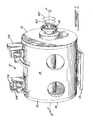
- the torque detecting device identified by the reference numeral 10, has an overall cylindrical shape and is mounted on a suitable support 12.
- the torque detector 10 comprises a cylindrical casing 14 provided with end walls 15 which is used to ensure the structural rigidity of the assembly as well as to protect the internal components of the torque detector 10.
- couplings 16 and 18 From the end walls 15 extend couplings 16 and 18 to be connected respectively to the rotor of a prime mover and to the rotor of a load.
- the coupling member 16 is mounted at one end of a shaft 20 integrally formed with a disc member 22 having a diameter substantially larger than the diameter of coupling 16.
- a disc member 22 On the disc member 22 is also formed an annular projection 24 with a central recess 26 defining a socket 28.
- the projection 24 is also provided with a hole 30 extending transversely to the recess 26.
- Disc member 22 is mounted for rotation to the casing 14 by a pair of roller bearing 32 which receive the shaft 20.
- a magnetic tape 34 On the periphery of disc member 22 is mounted a magnetic tape 34 on which is recorded a periodic signal, preferably of sinusoidal nature.
- Coupling member 18 is mounted on the shaft of a disc member 22a which is identical to the disc member 22 and, for that reason, it will not be described in details here.
- the elements of disc member 22a which correspond to those of disc member 22, are identified by the same reference numerals followed by the suffix "a".
- a torsion shaft 38 which is relatively thin and is made of an elastic material such as steel is mounted between disc members 22 and 22a. At the extremities of the torsion shaft 38 are formed enlargements or heads 40, 40a, respectively.
- heads 40 and 40a are identical, only the head 40 will be described, the elements of the head 40a identical to those of the head 40 will bear the same reference numerals followed by the suffix "a".
- the head 40 is deeply received within the socket 28 which is cross-drilled to form an opening 42 in register with the opening 30 for receiving a locking pin 44 preventing an unwanted removal of the head 40 from the socket 28.
- a metallic sleeve 46 is mounted between disc members 22 and 22a and extends coaxially with respect to the torsion shaft 38.
- the annular projection 24a is received within the metallic sleeve 46 at one end thereof which is designated by the reference numeral 48.
- a pair of openings 50, adjacent the extremity 48 are formed on the sleeve 46 for receiving the locking pin 44a therethrough.
- the annular projection 24 is received within the metallic sleeve 46, at the opposite end thereof, indicated at 51.
- a pair of slots 52 are formed on the metallic sleeve 46, adjacent the extremity 51, to receive the locking pin 44.
- the slots 52 extend in a circumferential direction with respect to the metallic sleeve 46.
- the inner diameter of the metallic sleeve 46, at the extremity 51 is slightly enlarged so as to create a loose fit with the projection 24 allowing the disc member 22 to rotate within limits with respect to the sleeve 46, by twisting the shaft 38, the extremities of the pin 44 moving in the slots 52.
- the length of the slots 52 determine the permissible amplitude of the movement between disc member 22 and the cylinder 46 which is calculated to avoid overtwisting the shaft 38.
- a pair of reading heads 54 and 56 (shown in phantom lines in Figure 2) are mounted to the casing 14, adjacent the periphery of disc member 22 for detecting the sinusoidal signal on the magnetic tape 34 in order to produce, each an output signal.
- the heads 54 and 56 which are Hall effect sensors are spaced from each other by a distance corresponding to a quarter of a period of the signal recorded on the magnetic tape 34.
- a single reading head 58 (also shown in phantom lines in Figure 2) which also is a Hall effect sensor is mounted on the casing 14, adjacent the disc member 22a for detecting the signal recorded on tape 34a.
- the operation of the torque detecting device 10, according to the present invention is as follows.
- the drive shaft of a prime mover which may be an electric motor, an internal combustion engine or the like, is connected to one of the coupling 16 or 18 and the shaft of a load which may be a pump, a generator or the like is connected to the opposite coupling.
- the prime mover may be connected to the coupling 16 and the load is connected to the coupling 18.
- the torque from the prime mover to the load is transmitted through the torque detecting device 10, more specifically by the torsion shaft 38 which, then, is slightly twisted about its axis, the twist angle being proportional to the amplitude of the torque applied.
- the twist angle creates a phase shift between the output signals generated by the reading head 54 and 56 and the reading head 58.
- the output signals from the reading heads 54, 56 and 58 are fed to a microcomputer operating according to a certain program, whose task is to calculate the torque transmitted from the prime mover to the load.
- the torque detector 10 defines in combination with a microcomputer a torque measuring device.
- microcomputer and the program which calculates the torque do not form part of this invention and, for that reason, they will not be described in details here. It should be understood that different type of microcomputers may be used with the torque detector according to this invention and also a variety of programs may be written to calculate the torque, from the output signals of the heads 54, 56 and 58 by determining the phase shift between the output signals.
- the output signal from the reading heads 54 and 56 are used to determine the direction of rotation of the disc members 22 and 22a. Taking as a reference the output signal from the head 56, if the output signal from the head 54 lags the signals from the head 56, the disc members 22 and 22a rotates clockwise, in the direction of the arrow 60. However, if the signal from the head 54 leads the signal from the head 56, then, the disc members 22 and 22a rotate a counter clockwise direction, as shown by the arrow 62.
- This information is useful in conjunction with the sign of the phase shift between the signal from the head 54 and 56 and the head 58 in order to determine to which one of the couplings 16 or 18, the prime mover is connected.
- the prime mover is connected to the coupling 16 and transmits the torque toward the coupling 18.
- each of the reading heads 54, 56 and 58 of the torque measuring device according to this invention is connected to a high-pass filter wherein the output signals generated by the reading heads are filtered before to be applied to the microcomputer. This arrangement improves the accuracy of the torque measuring device.
- the position of a periodic signal generated by a reading head is it the reading head 54, 56 or 58 with respect to a reference voltage level depends upon the gap 64 between the reading head and the magnetic tape. Therefore, in order to obtain a stable output signal, intersecting the reference voltage level at equidistant intervals, the gap 64 must remain constant. This requirement, however, is practically difficult to achieve since there is always a certain amount of run out in the radial direction in the disc members 22 and 22a on which the magnetic tapes 34 and 34a are mounted. Therefore, the gap 64 is not constant but changes during the rotation of the disc member and as a result, the output signal fluctuates.
- the output signal may be considered as being the sum of two components, the periodic signal recorded on the magnetic tape and a much lower frequency signal whose period corresponds to one revolution of the disc member carrying the magnetic tape.
- the specific structure of the high-pass filter is not essential to the invention because a variety of different filters may be used and the details as to their construction may be obtained from the literature.
- filters constructed from passive components such as capacitors and resistors may be employed.
- passive components such as capacitors and resistors
- Such filters are unexpensive but they have a major drawback in that a sharp cut-off characteristic may be obtained only at the expense of a strong signal attenuation which obviously is undesirable.
- the active filters do not have this drawback and while they are more expensive, the cost increase is largely compensated by their flexibility allowing one to tailor the filter precisely to the characteristics of the torque detector.
- the filter should have the sharpest cut-off response possible set at the highest number of revolutions per second that the disc members 22 and 22a and the torsion shaft 38 are susceptible to reach.
- the filter should have the flatest possible frequency response up to the maximum frequency that the output signals generated by the reading heads 54, 56 and 58 can reach.
Landscapes
- Physics & Mathematics (AREA)
- General Physics & Mathematics (AREA)
- Force Measurement Appropriate To Specific Purposes (AREA)
- Power Steering Mechanism (AREA)
- Manipulator (AREA)
Applications Claiming Priority (2)
| Application Number | Priority Date | Filing Date | Title |
|---|---|---|---|
| CA000532924A CA1306618C (en) | 1987-03-25 | 1987-03-25 | Torquemeter |
| CA532924 | 1987-03-25 |
Publications (2)
| Publication Number | Publication Date |
|---|---|
| EP0284508A2 true EP0284508A2 (de) | 1988-09-28 |
| EP0284508A3 EP0284508A3 (de) | 1990-05-30 |
Family
ID=4135278
Family Applications (1)
| Application Number | Title | Priority Date | Filing Date |
|---|---|---|---|
| EP88400681A Withdrawn EP0284508A3 (de) | 1987-03-25 | 1988-03-22 | Drehmomentmesser |
Country Status (4)
| Country | Link |
|---|---|
| US (1) | US4787255A (de) |
| EP (1) | EP0284508A3 (de) |
| JP (1) | JPS63255633A (de) |
| CA (1) | CA1306618C (de) |
Cited By (8)
| Publication number | Priority date | Publication date | Assignee | Title |
|---|---|---|---|---|
| EP0368687A2 (de) * | 1988-09-13 | 1990-05-16 | Consulab Inc. | Positionsmesseinrichtung |
| DE4232040A1 (de) * | 1991-09-26 | 1993-04-08 | Mazda Motor | Drehmomenterfassungssystem |
| US5247839A (en) * | 1989-10-25 | 1993-09-28 | Matsushita Electric Industrial Co., Ltd. | Torsion angle detection apparatus and torque sensor |
| DE19941683A1 (de) * | 1999-09-01 | 2001-03-22 | Siemens Ag | Messvorrichtung zur Ermittlung des drehmomentbedingten Torsionswinkels einer Welle |
| EP1199550A2 (de) * | 2000-10-19 | 2002-04-24 | GKN Walterscheid GmbH | Vorrichtung zum Messen von Drehmomenten in einer Antriebsanordnung |
| GB2427277A (en) * | 2005-06-14 | 2006-12-20 | Equipmake Ltd | Rotation sensor comprising magnetised strip disposed around circumference of rotating body |
| EP1239274B1 (de) * | 2001-03-09 | 2008-01-23 | Snr Roulements | Vorrichtung zur analogen Messung des Drehmomentes, Lenksäule und diese Vorrichtung beinhaltendes Modul |
| AT514415A1 (de) * | 2013-06-06 | 2014-12-15 | Kjion Technology Gmbh | Messgrößenaufnehmer und Messeinrichtung |
Families Citing this family (6)
| Publication number | Priority date | Publication date | Assignee | Title |
|---|---|---|---|---|
| EP0303676B1 (de) * | 1987-02-24 | 1991-03-20 | Renishaw plc | Teilung für wegmessapparat |
| US4926121A (en) * | 1987-03-25 | 1990-05-15 | Consulab, Inc. | Magnetic type position sensor for use in the construction of position indicators or torque meters |
| JPH04348239A (ja) * | 1991-03-25 | 1992-12-03 | Mazda Motor Corp | トルク・回転センサ |
| US5400663A (en) * | 1993-11-05 | 1995-03-28 | Bridges; Robert H. | Integral torsion sensor |
| GB0404458D0 (en) * | 2004-03-01 | 2004-03-31 | Zenith Oilfield Technology Ltd | Apparatus & method |
| US8001848B2 (en) * | 2007-12-18 | 2011-08-23 | Deere & Company | Torque measurement method and apparatus |
Citations (6)
| Publication number | Priority date | Publication date | Assignee | Title |
|---|---|---|---|---|
| GB1352275A (en) * | 1971-04-29 | 1974-05-08 | Simmonds Precision Products | Methods and systems of measuring torsion |
| US3871215A (en) * | 1971-05-10 | 1975-03-18 | Massachusetts Inst Technology | Opto-electronic apparatus to generate a pulse-modulated signal indicative of the mechanical state of a system |
| US3935733A (en) * | 1974-11-14 | 1976-02-03 | Resco, Inc. | Electronic transmission dynamometer |
| DE2815463A1 (de) * | 1977-05-05 | 1978-11-09 | Texaco Development Corp | Drehmomentmesser |
| GB2027211A (en) * | 1978-07-17 | 1980-02-13 | Resco Ltd | Method of measuring long shaft torque |
| DE3213589A1 (de) * | 1981-04-14 | 1982-11-04 | Aisin Seiki K.K., Kariya, Aichi | Drehmomentmessfuehler |
Family Cites Families (8)
| Publication number | Priority date | Publication date | Assignee | Title |
|---|---|---|---|---|
| US2947168A (en) * | 1954-06-23 | 1960-08-02 | Denis C Yang | Power indicator |
| US3170323A (en) * | 1959-09-30 | 1965-02-23 | Siemens Ag | Device for producing a torque or torsion responsive signal |
| US3142981A (en) * | 1960-11-22 | 1964-08-04 | Performance Measurements Compa | Digital force transducer |
| US3580352A (en) * | 1969-01-21 | 1971-05-25 | Gen Motors Corp | Steering torque servo |
| US3751975A (en) * | 1970-09-01 | 1973-08-14 | Ono Sokki Co Ltd | Torsion digital viscometer |
| DE2231571A1 (de) * | 1972-06-28 | 1974-01-10 | Daimler Benz Ag | Vorrichtung zum messen von verdrehungen mechanischer systeme |
| US4513626A (en) * | 1982-02-22 | 1985-04-30 | Nippon Soken, Inc. | Torque detector |
| US4448084A (en) * | 1982-03-17 | 1984-05-15 | Robert Bosch Gmbh | Non-contacting shaft position sensor |
-
1987
- 1987-03-25 CA CA000532924A patent/CA1306618C/en not_active Expired - Lifetime
- 1987-04-02 US US07/033,195 patent/US4787255A/en not_active Expired - Fee Related
-
1988
- 1988-03-22 EP EP88400681A patent/EP0284508A3/de not_active Withdrawn
- 1988-03-24 JP JP63070846A patent/JPS63255633A/ja active Pending
Patent Citations (6)
| Publication number | Priority date | Publication date | Assignee | Title |
|---|---|---|---|---|
| GB1352275A (en) * | 1971-04-29 | 1974-05-08 | Simmonds Precision Products | Methods and systems of measuring torsion |
| US3871215A (en) * | 1971-05-10 | 1975-03-18 | Massachusetts Inst Technology | Opto-electronic apparatus to generate a pulse-modulated signal indicative of the mechanical state of a system |
| US3935733A (en) * | 1974-11-14 | 1976-02-03 | Resco, Inc. | Electronic transmission dynamometer |
| DE2815463A1 (de) * | 1977-05-05 | 1978-11-09 | Texaco Development Corp | Drehmomentmesser |
| GB2027211A (en) * | 1978-07-17 | 1980-02-13 | Resco Ltd | Method of measuring long shaft torque |
| DE3213589A1 (de) * | 1981-04-14 | 1982-11-04 | Aisin Seiki K.K., Kariya, Aichi | Drehmomentmessfuehler |
Cited By (14)
| Publication number | Priority date | Publication date | Assignee | Title |
|---|---|---|---|---|
| EP0368687A2 (de) * | 1988-09-13 | 1990-05-16 | Consulab Inc. | Positionsmesseinrichtung |
| EP0368687A3 (de) * | 1988-09-13 | 1991-09-25 | Consulab Inc. | Positionsmesseinrichtung |
| US5247839A (en) * | 1989-10-25 | 1993-09-28 | Matsushita Electric Industrial Co., Ltd. | Torsion angle detection apparatus and torque sensor |
| DE4232040A1 (de) * | 1991-09-26 | 1993-04-08 | Mazda Motor | Drehmomenterfassungssystem |
| DE4232040C2 (de) * | 1991-09-26 | 1999-07-29 | Mazda Motor | Drehmomenterfassungssystem |
| DE19941683C2 (de) * | 1999-09-01 | 2001-06-21 | Siemens Ag | Messvorrichtung zur Ermittlung des drehmomentbedingten Torsionswinkels einer Welle |
| DE19941683A1 (de) * | 1999-09-01 | 2001-03-22 | Siemens Ag | Messvorrichtung zur Ermittlung des drehmomentbedingten Torsionswinkels einer Welle |
| EP1199550A2 (de) * | 2000-10-19 | 2002-04-24 | GKN Walterscheid GmbH | Vorrichtung zum Messen von Drehmomenten in einer Antriebsanordnung |
| EP1199550A3 (de) * | 2000-10-19 | 2003-04-23 | GKN Walterscheid GmbH | Vorrichtung zum Messen von Drehmomenten in einer Antriebsanordnung |
| US6651519B2 (en) | 2000-10-19 | 2003-11-25 | Gkn Walterscheid Gmbh | Device for measuring torque in a drive assembly |
| EP1239274B1 (de) * | 2001-03-09 | 2008-01-23 | Snr Roulements | Vorrichtung zur analogen Messung des Drehmomentes, Lenksäule und diese Vorrichtung beinhaltendes Modul |
| GB2427277A (en) * | 2005-06-14 | 2006-12-20 | Equipmake Ltd | Rotation sensor comprising magnetised strip disposed around circumference of rotating body |
| AT514415A1 (de) * | 2013-06-06 | 2014-12-15 | Kjion Technology Gmbh | Messgrößenaufnehmer und Messeinrichtung |
| AT514415B1 (de) * | 2013-06-06 | 2016-02-15 | Gharehgozloo Parastu Mag | Messgrößenaufnehmer und Messeinrichtung |
Also Published As
| Publication number | Publication date |
|---|---|
| US4787255A (en) | 1988-11-29 |
| CA1306618C (en) | 1992-08-25 |
| EP0284508A3 (de) | 1990-05-30 |
| JPS63255633A (ja) | 1988-10-21 |
Similar Documents
| Publication | Publication Date | Title |
|---|---|---|
| US4787255A (en) | Torquemeter | |
| JP5607877B2 (ja) | トルク測定方法およびその装置 | |
| AU769556B2 (en) | Sensor system for detecting an angle of rotation and/or a torque | |
| KR102361434B1 (ko) | 수학적으로 부드러운 클로들을 갖는 토크 센서 | |
| EP1300662B1 (de) | Drehwinkelsensor, Drehmomentsensor und Lenkvorrichtung | |
| US6782766B2 (en) | Apparatus for detecting torque, axial position and axial alignment of a rotating shaft | |
| KR100385377B1 (ko) | 회전축상의 토오크를 계산하기 위한 장치 및 방법 | |
| US5508608A (en) | Magnetic flux device for measuring rotary motions and for generating an electric alternating signal representative of the rotary motions | |
| EP0191560A2 (de) | Drehmomentüberwachungsvorrichtung | |
| US5285691A (en) | Apparatus for monitoring operation of a drive shaft | |
| US6834558B2 (en) | Combined torque measurement and clutch apparatus | |
| EP0882943A1 (de) | Vorrichtung zur Erfassung des momentanen Drehwinkels | |
| Vance et al. | Measurement of torsional vibration in rotating machinery | |
| KR20190138763A (ko) | 토크 측정장치 | |
| WO2001038885A1 (en) | Angular velocity monitor | |
| US6427537B1 (en) | Measuring equipment | |
| JPS59147231A (ja) | トルク計測用フレキシブルカツプリング | |
| JP2566617B2 (ja) | 軸の回転数の検出装置 | |
| SU1545108A1 (ru) | Устройство дл измерени крут щего момента | |
| GB2360596A (en) | Rotary coupling alignment using a permanent magnet and a pair of Hall effect sensors within respective coupling halves | |
| KR102170435B1 (ko) | 자동변속기용 펄스 제너레이터 회전각 검출해상도 증대방법 | |
| JPH045337B2 (de) | ||
| JPS61259132A (ja) | 回転軸のトルク測定方法及び装置 | |
| RU2085879C1 (ru) | Преобразователь крутящего момента | |
| RU2002114945A (ru) | Способ диагностирования валов роторных машин, передающих крутильные нагрузки |
Legal Events
| Date | Code | Title | Description |
|---|---|---|---|
| PUAI | Public reference made under article 153(3) epc to a published international application that has entered the european phase |
Free format text: ORIGINAL CODE: 0009012 |
|
| AK | Designated contracting states |
Kind code of ref document: A2 Designated state(s): AT BE CH DE ES FR GB GR IT LI LU NL SE |
|
| PUAL | Search report despatched |
Free format text: ORIGINAL CODE: 0009013 |
|
| AK | Designated contracting states |
Kind code of ref document: A3 Designated state(s): AT BE CH DE ES FR GB GR IT LI LU NL SE |
|
| STAA | Information on the status of an ep patent application or granted ep patent |
Free format text: STATUS: THE APPLICATION IS DEEMED TO BE WITHDRAWN |
|
| 18D | Application deemed to be withdrawn |
Effective date: 19901003 |