EP0284136A1 - Confocal laser scanning microscope - Google Patents
Confocal laser scanning microscope Download PDFInfo
- Publication number
- EP0284136A1 EP0284136A1 EP88200452A EP88200452A EP0284136A1 EP 0284136 A1 EP0284136 A1 EP 0284136A1 EP 88200452 A EP88200452 A EP 88200452A EP 88200452 A EP88200452 A EP 88200452A EP 0284136 A1 EP0284136 A1 EP 0284136A1
- Authority
- EP
- European Patent Office
- Prior art keywords
- detector
- light
- light beam
- filter
- scanning
- Prior art date
- Legal status (The legal status is an assumption and is not a legal conclusion. Google has not performed a legal analysis and makes no representation as to the accuracy of the status listed.)
- Granted
Links
- 238000005259 measurement Methods 0.000 claims abstract description 3
- 238000012545 processing Methods 0.000 claims abstract description 3
- 230000003287 optical effect Effects 0.000 claims description 8
- 230000000694 effects Effects 0.000 claims description 6
- 238000000386 microscopy Methods 0.000 claims description 3
- 239000013078 crystal Substances 0.000 claims description 2
- 238000000799 fluorescence microscopy Methods 0.000 claims 2
- 230000010287 polarization Effects 0.000 description 8
- 238000002360 preparation method Methods 0.000 description 6
- 238000000034 method Methods 0.000 description 3
- 238000004624 confocal microscopy Methods 0.000 description 2
- 238000004519 manufacturing process Methods 0.000 description 2
- 238000004377 microelectronic Methods 0.000 description 2
- 230000004075 alteration Effects 0.000 description 1
- 238000001218 confocal laser scanning microscopy Methods 0.000 description 1
- 238000012937 correction Methods 0.000 description 1
- 230000000875 corresponding effect Effects 0.000 description 1
- 238000013461 design Methods 0.000 description 1
- 239000006185 dispersion Substances 0.000 description 1
- RUZYUOTYCVRMRZ-UHFFFAOYSA-N doxazosin Chemical compound C1OC2=CC=CC=C2OC1C(=O)N(CC1)CCN1C1=NC(N)=C(C=C(C(OC)=C2)OC)C2=N1 RUZYUOTYCVRMRZ-UHFFFAOYSA-N 0.000 description 1
- 230000006870 function Effects 0.000 description 1
- 230000015654 memory Effects 0.000 description 1
- 239000002184 metal Substances 0.000 description 1
- 238000000399 optical microscopy Methods 0.000 description 1
- 210000001747 pupil Anatomy 0.000 description 1
Images

Classifications
-
- G—PHYSICS
- G02—OPTICS
- G02B—OPTICAL ELEMENTS, SYSTEMS OR APPARATUS
- G02B21/00—Microscopes
- G02B21/0004—Microscopes specially adapted for specific applications
- G02B21/002—Scanning microscopes
- G02B21/0024—Confocal scanning microscopes (CSOMs) or confocal "macroscopes"; Accessories which are not restricted to use with CSOMs, e.g. sample holders
- G02B21/0052—Optical details of the image generation
- G02B21/0068—Optical details of the image generation arrangements using polarisation
-
- G—PHYSICS
- G02—OPTICS
- G02B—OPTICAL ELEMENTS, SYSTEMS OR APPARATUS
- G02B21/00—Microscopes
- G02B21/0004—Microscopes specially adapted for specific applications
- G02B21/002—Scanning microscopes
- G02B21/0024—Confocal scanning microscopes (CSOMs) or confocal "macroscopes"; Accessories which are not restricted to use with CSOMs, e.g. sample holders
- G02B21/0032—Optical details of illumination, e.g. light-sources, pinholes, beam splitters, slits, fibers
-
- G—PHYSICS
- G02—OPTICS
- G02B—OPTICAL ELEMENTS, SYSTEMS OR APPARATUS
- G02B21/00—Microscopes
- G02B21/0004—Microscopes specially adapted for specific applications
- G02B21/002—Scanning microscopes
- G02B21/0024—Confocal scanning microscopes (CSOMs) or confocal "macroscopes"; Accessories which are not restricted to use with CSOMs, e.g. sample holders
- G02B21/0036—Scanning details, e.g. scanning stages
-
- G—PHYSICS
- G02—OPTICS
- G02B—OPTICAL ELEMENTS, SYSTEMS OR APPARATUS
- G02B21/00—Microscopes
- G02B21/0004—Microscopes specially adapted for specific applications
- G02B21/002—Scanning microscopes
- G02B21/0024—Confocal scanning microscopes (CSOMs) or confocal "macroscopes"; Accessories which are not restricted to use with CSOMs, e.g. sample holders
- G02B21/0036—Scanning details, e.g. scanning stages
- G02B21/0048—Scanning details, e.g. scanning stages scanning mirrors, e.g. rotating or galvanomirrors, MEMS mirrors
-
- G—PHYSICS
- G02—OPTICS
- G02B—OPTICAL ELEMENTS, SYSTEMS OR APPARATUS
- G02B21/00—Microscopes
- G02B21/0004—Microscopes specially adapted for specific applications
- G02B21/002—Scanning microscopes
- G02B21/0024—Confocal scanning microscopes (CSOMs) or confocal "macroscopes"; Accessories which are not restricted to use with CSOMs, e.g. sample holders
- G02B21/0052—Optical details of the image generation
- G02B21/0072—Optical details of the image generation details concerning resolution or correction, including general design of CSOM objectives
-
- G—PHYSICS
- G02—OPTICS
- G02B—OPTICAL ELEMENTS, SYSTEMS OR APPARATUS
- G02B21/00—Microscopes
- G02B21/0004—Microscopes specially adapted for specific applications
- G02B21/002—Scanning microscopes
- G02B21/0024—Confocal scanning microscopes (CSOMs) or confocal "macroscopes"; Accessories which are not restricted to use with CSOMs, e.g. sample holders
- G02B21/0052—Optical details of the image generation
- G02B21/0076—Optical details of the image generation arrangements using fluorescence or luminescence
-
- G—PHYSICS
- G02—OPTICS
- G02B—OPTICAL ELEMENTS, SYSTEMS OR APPARATUS
- G02B21/00—Microscopes
- G02B21/0004—Microscopes specially adapted for specific applications
- G02B21/002—Scanning microscopes
- G02B21/0024—Confocal scanning microscopes (CSOMs) or confocal "macroscopes"; Accessories which are not restricted to use with CSOMs, e.g. sample holders
- G02B21/008—Details of detection or image processing, including general computer control
- G02B21/0084—Details of detection or image processing, including general computer control time-scale detection, e.g. strobed, ultra-fast, heterodyne detection
Definitions
- the invention relates to a confocal laser scanning microscope provided with a laser as point light source, a deflection system for the line and frame scanning and a lens system, at least one objective near the object, an object stage, a spatial filter and a detector, and an electronic control and image-processing sys tem, the object being scanned point by point by the light beam and measurements being made with the detector only where the point light source is focused so that out-of-focus light is not detected, as a result of which resolution and contrast considerably improve in three dimensions, in particular, axially to the image plane, and 3D information can be derived from the object.
- a confocal laser scanning microscope is known from the book entitled "Theory and Practice of Scanning Optical Microscopy" by T Wilson and C Sheppard, Academic Press, 1984.
- the focused laser spot is scanned over the stationary object or preparation.
- Use is generally made of galvanometric deflection by means of mirror galvanometers in said scanning movement of the focused laser spot both for the line scanning and for the frame scanning.
- the object is also often scanned by means of the moving object stage with respect to a stationary focus laser spot.
- the disadvantage of such methods of scanning is that they have a mechanical nature and are therefore inherently slow. This also produces long frame times.
- the object of the invention is to eliminate these problems and, in a confocal laser scanning microscope, to achieve a deflection which can operate with high speed and flexibility, i.e. with variable scanning amplitude and various types of microscopy, and which has an optically relatively simple embodiment.
- a deflection which can operate with high speed and flexibility, i.e. with variable scanning amplitude and various types of microscopy, and which has an optically relatively simple embodiment.
- rapid line and frame scanning it is then possible, in a very short time, to combine electronically a number of thin image sections to form an image with an increased depth of focus.
- the deflection system comprises an acousto-optical deflector and, for the slower field scanning, it comprises another deflector constructed in a manner such that at least the frame-scanning movement of the return light beam is completely eliminated, as a result of which the return light is focused on the spatial filter.
- the other deflector in the deflection system may consist of a mirror galvanometer.
- a further advantageous embodiment in which a beam splitter is incorporated in the light path in order to split off the return light beam after the acousto-optical deflector and to direct it to the detector via a further objective, is characterized in that the deflection system with the acousto-optical deflector is also constructed in a manner such that the line-scanning movement of the return light beam is also completely eliminated, and in that the spatial filter is a pin-hole filter which forms a point detector with the subsequent detector.
- a quarter-wave plate may be incorporated in the outward path in front of the objective in order to supress the disturbing effect of optical reflections in the outward path which are produced by the use of the acousto-optical deflector with the necessity, associated therewith, of using several lenses.
- a polarizing filter whose polarization direction is perpendicular to the polarization direction of the outward light should then be incorporated in the path of the reflected light beam.
- the outward linearly polarized light is converted into circularly polarized light by the quarter-wave plate.
- said circularly polarized light After reflection by the object, said circularly polarized light again passes through the quarter-wave plate so that light is linearly polarized with a polarization direction perpendicular to that of the incident beam.
- the polarization filter incorporated in the path of the reflected light transmits only light having a polarization direction perpendicular to that of the outward beam, and this can then be detected by the point detector.
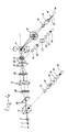
- the first embodiment is explained with reference to Figure 1.
- the laser light beam 1 first passes the lenses 2 and 3 forming together a beam expansion optical system, followed by a beam splitter 4, an acousto-optical deflector 5 having a planocylindrical lens 5.1 and a planoconvex lens 5.2 both at the entrance and at the exit side, a lens 6, a deflector 7, which may be a mirror galvanometer, a lens 8, a quarter-wave plate 16, and an objective 9.
- an object not shown, is further placed on a stationary object stage.
- the reflected light traverses a return path identical to the outward path up to the beam splitter 4 after which it is split off to a polarizing filter 11, a further objective 13, a spatial filter 14, a lens 17, a band pass or cut-off filter 12, and finally a detector 15.
- the expansion optical system mentioned which has an expansion factor of three, ensures, in combination with the other optical elements, that the light completely fills the entrance pupil of the objective 9.
- the beam splitter 4 ensures that light reflected by the object is separated from the outward laser light.
- the acousto-optical deflector 5 ensures more rapid line scanning over the object, and the mirror galvanometer 7 ensures a relatively slower frame scanning across the object.
- the acousto-optical deflector can achieve a deflection of the laser beam with such a high frequency that the latter takes place with video speed or even higher speed.
- the lens 6 increases the angle through which the laser beam is deflected by the acousto-optical deflector.
- the focused spot of the laser beam ends up in a position such that the objective is used in the correct manner.
- the mirror galvanometer 7 is at the focal point of said lens and in the centre point of the lens 8.
- the objective 9 focuses the outward laser beam 18 on the object, which may be, for example, a biological preparation or any other object.
- the laser light 19 reflected or scattered by the object follows the same optical path backwards up to the beam splitter 4. After this, the reflected light follows the path already specified through the elements 11, 13, 14, 17 and 12 up to the detector 15.
- the scanning X-Y movement of the laser beam introduced by the acousto-optical detector and the mirror galvanometer is eliminated again on the return path so that the reflected light is focused on the stationary spatial filter 14, which is a pin-hole filter (2-micron hole). This filter, with the detector immediately behind it, forms a point detector. As a result of this the microscope has confocal characteristics.
- the disturbing reflections introduced in the outward path by the acousto-optical deflector are eliminated by means of a quarter-wave plate 16 incorporated in front of the objective 9 and a polarizing filter 11 incorporated after the beam splitter.
- the outward linearly polarized light is converted into circularly polarized light by the plate 16, after which said light, after reflection, again passes through said quarter-wave plate and is converted again into linearly polarized light with a polarization direction perpendicular to the incident beam.
- the polarization filter 11 incorporated after the beam splitter is also adjusted to this polarization direction so that only reflections from the object and the objective 9 are detected.
- Such a spatial filter may advantageously be displaced by three piezoelectric crystals, each for one of the three axes of the XYZ coordinate system, as indicated in Figure 3.
- such a microscope can be used for examining fluorescent preparations which have this property inherently or have been marked for this purpose.
- the light emitted as a result when light is incident on the object has a wavelength other than that of the outward laser light.
- a band filter or cut-off filter 12 in the return path which is matched to the expected wavelength of the return light, the latter can be selectively transmitted so that no disturbing effect is experienced from the reflected laser light. Since the light of differing wavelengths also undergoes a different deflection in the acousto-optical deflector 5, the spatial filter 12 must be arranged in another position corresponding to the angular dispersion of the acousto-optical deflector.
- FIG. 4 indicates a second embodiment.
- a diachromatic mirror 20 has been incorporated in the light path between the planocylindrical lens 5.1 and the lens 6. Said mirror transmits the (short-wave) laser light and deflects the long-wave return light originating, for example, from fluorescence. This light is passed through a correction lens 21 and focused with the objective 22 on a special spatial filter 23 which is a slit filter (330 m x 1 m), as a result of which this system has confocal characteristics. In this manner, a line detector is formed with the subsequent lens 24 and detector 26. Between the lens 24 and the detector 26 one more band pass or cut-off filter 25 has been incorporated which has the same function as that of the band pass or cut-off filter 12. With this embodiment, return light which has a wavelength other than that of the outward light can be advantageously examined if the acousto-optical deflector has too low an efficiency for said light, i.e. brings about too large an atten
- each image contains 1000 lines.
- the detector and the subsequent electronics which measure the half tone of a pixel which have to have at least a response of not more than 50 nsec.
- an image with increased depth of focus can be built up by combining a number of thin image sections.
- 20 sections situated underneath each other can be combined in one second so that a object which is 20 sections thick can be reproduced with complete sharpness.
- such a microscope according to the invention having a line-scanning frequency of, for example, 20-30 kHz and a frame-scanning frequency of, for example, 90 Hz can also be used in forensic examination and in the microelectronics industry. In all cases the fact that it is not necessary with this microscope to work with the object under vacuum is of great advantage. In contrast to the scanning electron microscope, for which the preparations have to be covered with a thin conductive metal layer, this method is also non-destructive. The fact that, in the microscope according to the invention, no mechanical forces are exerted on the preparation is also an advantage over systems in which the preparation is scanned. In the microelectronics industry, this microscope can be used for production control of LSI and VLSI chips, the production of "custom design" chips and also the functional control of chips by means of the so-called "optical beam induced current" method.
- the present microscope can also be used advantageously for examining optical memories.
Landscapes
- Physics & Mathematics (AREA)
- Chemical & Material Sciences (AREA)
- Analytical Chemistry (AREA)
- General Physics & Mathematics (AREA)
- Optics & Photonics (AREA)
- Engineering & Computer Science (AREA)
- Computer Vision & Pattern Recognition (AREA)
- General Engineering & Computer Science (AREA)
- Microscoopes, Condenser (AREA)
- Investigating Or Analysing Materials By Optical Means (AREA)
- Mechanical Optical Scanning Systems (AREA)
- Investigating, Analyzing Materials By Fluorescence Or Luminescence (AREA)
Abstract
Description
- The invention relates to a confocal laser scanning microscope provided with a laser as point light source, a deflection system for the line and frame scanning and a lens system, at least one objective near the object, an object stage, a spatial filter and a detector, and an electronic control and image-processing sys tem, the object being scanned point by point by the light beam and measurements being made with the detector only where the point light source is focused so that out-of-focus light is not detected, as a result of which resolution and contrast considerably improve in three dimensions, in particular, axially to the image plane, and 3D information can be derived from the object. Such a confocal laser scanning microscope is known from the book entitled "Theory and Practice of Scanning Optical Microscopy" by T Wilson and C Sheppard, Academic Press, 1984.
- In such a microscope, the focused laser spot is scanned over the stationary object or preparation. Use is generally made of galvanometric deflection by means of mirror galvanometers in said scanning movement of the focused laser spot both for the line scanning and for the frame scanning. The object is also often scanned by means of the moving object stage with respect to a stationary focus laser spot. The disadvantage of such methods of scanning is that they have a mechanical nature and are therefore inherently slow. This also produces long frame times.
- The object of the invention is to eliminate these problems and, in a confocal laser scanning microscope, to achieve a deflection which can operate with high speed and flexibility, i.e. with variable scanning amplitude and various types of microscopy, and which has an optically relatively simple embodiment. As a result of rapid line and frame scanning, it is then possible, in a very short time, to combine electronically a number of thin image sections to form an image with an increased depth of focus.
- In a confocal laser scanning microscope of the type mentioned in the introduction, this is thus achieved according to the invention in that, for the more rapid line scanning, the deflection system comprises an acousto-optical deflector and, for the slower field scanning, it comprises another deflector constructed in a manner such that at least the frame-scanning movement of the return light beam is completely eliminated, as a result of which the return light is focused on the spatial filter.
- The use of an acousto-optical deflector is known per se in the case of non-confocal laser scanning micro scopy. If it is used in confocal microscopy however, the known disadvantages of the dispersive nature and the necessity of using several lenses then occur, as a result of which, respectively, confocal microscopy using light to be observed of a wavelength other than that of the light incident on the object (fluorescence etc) is not readily possible and the disturbing effect of reflections at surfaces of the lenses used is considerable. In addition, the latter have to be of good quality to avoid aberrations.
- In an advantageous embodiment, the other deflector in the deflection system may consist of a mirror galvanometer.
- A further advantageous embodiment, in which a beam splitter is incorporated in the light path in order to split off the return light beam after the acousto-optical deflector and to direct it to the detector via a further objective, is characterized in that the deflection system with the acousto-optical deflector is also constructed in a manner such that the line-scanning movement of the return light beam is also completely eliminated, and in that the spatial filter is a pin-hole filter which forms a point detector with the subsequent detector.
- Advantageously, in the confocal laser scanning microscope according to the invention a quarter-wave plate may be incorporated in the outward path in front of the objective in order to supress the disturbing effect of optical reflections in the outward path which are produced by the use of the acousto-optical deflector with the necessity, associated therewith, of using several lenses. A polarizing filter, whose polarization direction is perpendicular to the polarization direction of the outward light should then be incorporated in the path of the reflected light beam. The outward linearly polarized light is converted into circularly polarized light by the quarter-wave plate. After reflection by the object, said circularly polarized light again passes through the quarter-wave plate so that light is linearly polarized with a polarization direction perpendicular to that of the incident beam. The polarization filter incorporated in the path of the reflected light transmits only light having a polarization direction perpendicular to that of the outward beam, and this can then be detected by the point detector.
- The invention will now be explained in more detail on the basis of an exemplary embodiment with reference to the drawings, in which:
- Figure 1 gives a diagrammatic view of a first embodiment of the confocal laser scanning microscope according to the invention;
- Figure 2 gives a diagrammatic view of the manner in which the light beam is incident on the objective;
- Figure 3 gives a detailed view of the spatial filter in the microscope of Figure 1; and
- Figure 4 gives a diagrammatic view of a second embodiment of the confocal laser scanning microscope according to the invention.
- The first embodiment is explained with reference to Figure 1. The
laser light beam 1 first passes thelenses beam splitter 4, an acousto-optical deflector 5 having a planocylindrical lens 5.1 and a planoconvex lens 5.2 both at the entrance and at the exit side, alens 6, adeflector 7, which may be a mirror galvanometer, alens 8, a quarter-wave plate 16, and an objective 9. In theobject plane 10, an object, not shown, is further placed on a stationary object stage. The reflected light traverses a return path identical to the outward path up to thebeam splitter 4 after which it is split off to a polarizingfilter 11, afurther objective 13, aspatial filter 14, alens 17, a band pass or cut-off filter 12, and finally adetector 15. - The expansion optical system mentioned, which has an expansion factor of three, ensures, in combination with the other optical elements, that the light completely fills the entrance pupil of the
objective 9. Thebeam splitter 4 ensures that light reflected by the object is separated from the outward laser light. The acousto-optical deflector 5 ensures more rapid line scanning over the object, and themirror galvanometer 7 ensures a relatively slower frame scanning across the object. In this connection, the acousto-optical deflector can achieve a deflection of the laser beam with such a high frequency that the latter takes place with video speed or even higher speed. - The
lens 6 increases the angle through which the laser beam is deflected by the acousto-optical deflector. The focused spot of the laser beam ends up in a position such that the objective is used in the correct manner. Themirror galvanometer 7 is at the focal point of said lens and in the centre point of thelens 8. As a result of this, the laser beam is stationary both at the mirror galvanometer and at the rear side of the objective so that, at these positions, only the angle of incidence, but not the position of incidence, of the laser beam changes. In this connection, compare also Figure 2. - The
objective 9 focuses theoutward laser beam 18 on the object, which may be, for example, a biological preparation or any other object. Thelaser light 19 reflected or scattered by the object follows the same optical path backwards up to thebeam splitter 4. After this, the reflected light follows the path already specified through theelements detector 15. The scanning X-Y movement of the laser beam introduced by the acousto-optical detector and the mirror galvanometer is eliminated again on the return path so that the reflected light is focused on the stationaryspatial filter 14, which is a pin-hole filter (2-micron hole). This filter, with the detector immediately behind it, forms a point detector. As a result of this the microscope has confocal characteristics. - In this first embodiment according to the invention, the disturbing reflections introduced in the outward path by the acousto-optical deflector are eliminated by means of a quarter-
wave plate 16 incorporated in front of the objective 9 and a polarizingfilter 11 incorporated after the beam splitter. The outward linearly polarized light is converted into circularly polarized light by theplate 16, after which said light, after reflection, again passes through said quarter-wave plate and is converted again into linearly polarized light with a polarization direction perpendicular to the incident beam. Thepolarization filter 11 incorporated after the beam splitter is also adjusted to this polarization direction so that only reflections from the object and the objective 9 are detected. - Further disadvantageous effects may possibly be caused by the dispersive nature of the acousto-optical deflector, as a result of which return light of a wavelength (for example, fluorescence) other than the laser light no longer passes through the spatial filter, are taken care of by displacing the
spatial filter 14 in those cases. Such a spatial filter may advantageously be displaced by three piezoelectric crystals, each for one of the three axes of the XYZ coordinate system, as indicated in Figure 3. - Advantageously, such a microscope can be used for examining fluorescent preparations which have this property inherently or have been marked for this purpose. The light emitted as a result when light is incident on the object has a wavelength other than that of the outward laser light. By using a band filter or cut-off
filter 12 in the return path which is matched to the expected wavelength of the return light, the latter can be selectively transmitted so that no disturbing effect is experienced from the reflected laser light. Since the light of differing wavelengths also undergoes a different deflection in the acousto-optical deflector 5, thespatial filter 12 must be arranged in another position corresponding to the angular dispersion of the acousto-optical deflector. - Figure 4 indicates a second embodiment. A
diachromatic mirror 20 has been incorporated in the light path between the planocylindrical lens 5.1 and thelens 6. Said mirror transmits the (short-wave) laser light and deflects the long-wave return light originating, for example, from fluorescence. This light is passed through acorrection lens 21 and focused with the objective 22 on a specialspatial filter 23 which is a slit filter (330 m x 1 m), as a result of which this system has confocal characteristics. In this manner, a line detector is formed with thesubsequent lens 24 anddetector 26. Between thelens 24 and thedetector 26 one more band pass or cut-offfilter 25 has been incorporated which has the same function as that of the band pass or cut-offfilter 12. With this embodiment, return light which has a wavelength other than that of the outward light can be advantageously examined if the acousto-optical deflector has too low an efficiency for said light, i.e. brings about too large an attenuation. - With this microscope it is possible to assemble, for example, 20 images per second at a line frequency of 20 kHz. That is to say, each image contains 1000 lines. With such a number of 20,000 lines per second and if there are to be 1000 image points or pixels per line, the detector and the subsequent electronics which measure the half tone of a pixel which have to have at least a response of not more than 50 nsec. Advantageously, with such a fast image assembly, an image with increased depth of focus can be built up by combining a number of thin image sections. According to the above example, 20 sections situated underneath each other can be combined in one second so that a object which is 20 sections thick can be reproduced with complete sharpness.
- In addition to being used in the field of application of biology, such a microscope according to the invention having a line-scanning frequency of, for example, 20-30 kHz and a frame-scanning frequency of, for example, 90 Hz can also be used in forensic examination and in the microelectronics industry. In all cases the fact that it is not necessary with this microscope to work with the object under vacuum is of great advantage. In contrast to the scanning electron microscope, for which the preparations have to be covered with a thin conductive metal layer, this method is also non-destructive. The fact that, in the microscope according to the invention, no mechanical forces are exerted on the preparation is also an advantage over systems in which the preparation is scanned. In the microelectronics industry, this microscope can be used for production control of LSI and VLSI chips, the production of "custom design" chips and also the functional control of chips by means of the so-called "optical beam induced current" method.
- The present microscope can also be used advantageously for examining optical memories.
Claims (6)
Priority Applications (1)
| Application Number | Priority Date | Filing Date | Title |
|---|---|---|---|
| AT88200452T ATE79476T1 (en) | 1987-03-13 | 1988-03-09 | CONFOCAL LASER SCANNING MICROSCOPE. |
Applications Claiming Priority (2)
| Application Number | Priority Date | Filing Date | Title |
|---|---|---|---|
| NL8700612 | 1987-03-13 | ||
| NL8700612A NL8700612A (en) | 1987-03-13 | 1987-03-13 | CONFOCAL LASER SCANNING MICROSCOPE. |
Publications (2)
| Publication Number | Publication Date |
|---|---|
| EP0284136A1 true EP0284136A1 (en) | 1988-09-28 |
| EP0284136B1 EP0284136B1 (en) | 1992-08-12 |
Family
ID=19849704
Family Applications (1)
| Application Number | Title | Priority Date | Filing Date |
|---|---|---|---|
| EP88200452A Expired - Lifetime EP0284136B1 (en) | 1987-03-13 | 1988-03-09 | Confocal laser scanning microscope |
Country Status (7)
| Country | Link |
|---|---|
| US (1) | US4863226A (en) |
| EP (1) | EP0284136B1 (en) |
| JP (2) | JPS63298211A (en) |
| AT (1) | ATE79476T1 (en) |
| DE (1) | DE3873570T2 (en) |
| ES (1) | ES2034154T3 (en) |
| NL (1) | NL8700612A (en) |
Cited By (7)
| Publication number | Priority date | Publication date | Assignee | Title |
|---|---|---|---|---|
| WO1995030167A1 (en) * | 1994-04-30 | 1995-11-09 | Medical Research Council | Scanning confocal optical microscope |
| US5691839A (en) * | 1993-04-15 | 1997-11-25 | Kowa Company Ltd. | Laser scanning optical microscope |
| WO2002067037A3 (en) * | 2001-02-16 | 2002-10-24 | Evotec Ag | Microscope |
| EP1467235A1 (en) * | 2003-04-08 | 2004-10-13 | VisiTech International Ltd. | Fast multi-line laser confocal scanning microscope |
| EP1570411A4 (en) * | 2002-10-22 | 2007-05-30 | Univ Rice William M | CONFOCAL HIGH SPEED MICROSCOPE WITH RANDOM ACCESS |
| CN105486638A (en) * | 2015-11-30 | 2016-04-13 | 哈尔滨工业大学 | Super-resolution array scanning structure light illumination imaging apparatus and imaging method thereof |
| CN108519329A (en) * | 2018-03-26 | 2018-09-11 | 华中科技大学 | A kind of line co-focusing imaging device of multi-channel scanning and detection |
Families Citing this family (44)
| Publication number | Priority date | Publication date | Assignee | Title |
|---|---|---|---|---|
| US5200838A (en) * | 1988-05-27 | 1993-04-06 | The University Of Connecticut | Lateral effect imaging system |
| JP2525894B2 (en) * | 1989-04-07 | 1996-08-21 | 浜松ホトニクス株式会社 | Fluorescence characteristic inspection device for semiconductor samples |
| JP2525893B2 (en) * | 1989-04-07 | 1996-08-21 | 浜松ホトニクス株式会社 | Fluorescence characteristic inspection device |
| US5225924A (en) * | 1989-04-07 | 1993-07-06 | Dainippon Screen Mfg. Co., Ltd. | Optical beam scanning system |
| US5002348A (en) * | 1989-05-24 | 1991-03-26 | E. I. Du Pont De Nemours And Company | Scanning beam optical signal processor |
| EP0418928B1 (en) * | 1989-09-22 | 1996-05-01 | Fuji Photo Film Co., Ltd. | Scanning microscope and scanning mechanism for the same |
| US5034613A (en) * | 1989-11-14 | 1991-07-23 | Cornell Research Foundation, Inc. | Two-photon laser microscopy |
| US5386112A (en) * | 1990-06-29 | 1995-01-31 | Dixon; Arthur E. | Apparatus and method for transmitted-light and reflected-light imaging |
| US5260578A (en) * | 1991-04-10 | 1993-11-09 | Mayo Foundation For Medical Education And Research | Confocal imaging system for visible and ultraviolet light |
| DE69229777T3 (en) * | 1991-04-10 | 2010-12-30 | Mayo Foundation For Medical Education And Research, Rochester | CONFOCUS PICTURE SYSTEM FOR VISIBLE AND UV LIGHT |
| US5306902A (en) * | 1992-09-01 | 1994-04-26 | International Business Machines Corporation | Confocal method and apparatus for focusing in projection lithography |
| US5479252A (en) * | 1993-06-17 | 1995-12-26 | Ultrapointe Corporation | Laser imaging system for inspection and analysis of sub-micron particles |
| USH1530H (en) * | 1993-06-17 | 1996-05-07 | Ultrapointe Corporation | Surface extraction from a three-dimensional data set |
| US5923430A (en) | 1993-06-17 | 1999-07-13 | Ultrapointe Corporation | Method for characterizing defects on semiconductor wafers |
| EP0646768A3 (en) * | 1993-09-29 | 1997-05-14 | Ushio Electric Inc | Confocal optical microscope and length measuring device using this microscope. |
| US5587832A (en) * | 1993-10-20 | 1996-12-24 | Biophysica Technologies, Inc. | Spatially light modulated confocal microscope and method |
| US5923466A (en) * | 1993-10-20 | 1999-07-13 | Biophysica Technologies, Inc. | Light modulated confocal optical instruments and method |
| US5561611A (en) * | 1994-10-04 | 1996-10-01 | Noran Instruments, Inc. | Method and apparatus for signal restoration without knowledge of the impulse response function of the signal acquisition system |
| DE19510102C1 (en) * | 1995-03-20 | 1996-10-02 | Rainer Dr Uhl | Confocal fluorescence microscope |
| WO1997011355A1 (en) | 1995-09-19 | 1997-03-27 | Cornell Research Foundation, Inc. | Multi-photon laser microscopy |
| US6148114A (en) * | 1996-11-27 | 2000-11-14 | Ultrapointe Corporation | Ring dilation and erosion techniques for digital image processing |
| DE19758744C2 (en) * | 1997-01-27 | 2003-08-07 | Zeiss Carl Jena Gmbh | Laser Scanning Microscope |
| US6771417B1 (en) * | 1997-08-01 | 2004-08-03 | Carl Zeiss Jena Gmbh | Applications of adaptive optics in microscopy |
| DE19733193B4 (en) * | 1997-08-01 | 2005-09-08 | Carl Zeiss Jena Gmbh | Microscope with adaptive optics |
| US6098031A (en) * | 1998-03-05 | 2000-08-01 | Gsi Lumonics, Inc. | Versatile method and system for high speed, 3D imaging of microscopic targets |
| US6366357B1 (en) | 1998-03-05 | 2002-04-02 | General Scanning, Inc. | Method and system for high speed measuring of microscopic targets |
| US5936728A (en) * | 1998-04-14 | 1999-08-10 | Noran Instruments, Inc. | Flash photolysis method and apparatus |
| WO2000055669A1 (en) * | 1999-03-18 | 2000-09-21 | Lucid, Inc. | System and method for enhancing confocal reflectance images of tissue specimens |
| US6720547B1 (en) * | 1999-03-18 | 2004-04-13 | Lucid, Inc. | System and method for enhancing confocal reflectance images of tissue specimens |
| US6548796B1 (en) * | 1999-06-23 | 2003-04-15 | Regents Of The University Of Minnesota | Confocal macroscope |
| US6449039B1 (en) | 1999-07-28 | 2002-09-10 | Thermo Noran Inc. | Laser scanning fluorescence microscopy with compensation for spatial dispersion of fast laser pulses |
| DE10050529B4 (en) * | 2000-10-11 | 2016-06-09 | Leica Microsystems Cms Gmbh | Method for beam control in a scanning microscope, arrangement for beam control in a scanning microscope and scanning microscope |
| US7139122B1 (en) * | 2000-10-17 | 2006-11-21 | Lucid, Inc. | System and method for enhancing confocal reflectance images of tissue specimens |
| AU2002245119A1 (en) | 2000-12-15 | 2002-07-30 | Sloan-Kettering Institute For Cancer Research | Beam-steering of multi-chromatic light using acousto-optical deflectors and dispersion-compensatory optics |
| US6750974B2 (en) | 2002-04-02 | 2004-06-15 | Gsi Lumonics Corporation | Method and system for 3D imaging of target regions |
| JP4987233B2 (en) * | 2005-01-06 | 2012-07-25 | オリンパス株式会社 | Laser scanning microscope |
| EP1895905B1 (en) | 2005-05-12 | 2024-10-23 | Lucid, Inc. | Confocal scanning microscope having optical and scanning systems which provide a handheld imaging head |
| DE102007021378A1 (en) * | 2007-05-04 | 2008-11-06 | Ape Angewandte Physik Und Elektronik Gmbh | A method and optical arrangement for generating a non-linear optical signal on a stimulated by an excitation field material and use of the method and the optical arrangement |
| KR101119381B1 (en) * | 2009-06-18 | 2012-03-07 | 한국과학기술원 | Device and system for measuring properties of cells and method of measuring properties of cells using the same |
| CN101904735B (en) * | 2010-07-20 | 2013-05-08 | 苏州微清医疗器械有限公司 | Quick titling mirror-based wide view field confocal scanning microscope |
| CN102885612A (en) * | 2012-02-14 | 2013-01-23 | 苏州微清医疗器械有限公司 | Fundus imaging equipment for clinical diagnosis |
| CN106442335B (en) * | 2016-12-16 | 2024-04-09 | 中国科学院工程热物理研究所 | Microscopic visual pumping detection heat reflection system |
| CN112261253B (en) * | 2020-10-15 | 2022-05-03 | 浙江大华技术股份有限公司 | Confocal compensation filter control method, confocal compensation filter control device, storage medium, and electronic device |
| WO2023193480A1 (en) * | 2022-04-08 | 2023-10-12 | 南京博视医疗科技有限公司 | Retinal imaging apparatus and imaging method thereof |
Citations (2)
| Publication number | Priority date | Publication date | Assignee | Title |
|---|---|---|---|---|
| GB2152697A (en) * | 1983-10-25 | 1985-08-07 | Atomic Energy Authority Uk | Improvements in or relating to scanning optical microscopes |
| US4634880A (en) * | 1982-04-19 | 1987-01-06 | Siscan Systems, Inc. | Confocal optical imaging system with improved signal-to-noise ratio |
Family Cites Families (8)
| Publication number | Priority date | Publication date | Assignee | Title |
|---|---|---|---|---|
| JPS5118136B1 (en) * | 1970-11-25 | 1976-06-08 | ||
| US4044363A (en) * | 1974-12-23 | 1977-08-23 | Dymo Industries, Inc. | Laser photocomposition system and method |
| DE3427611A1 (en) * | 1984-07-26 | 1988-06-09 | Bille Josef | LASER BEAM LITHOGRAPH |
| US4640626A (en) * | 1984-09-13 | 1987-02-03 | Siemens Aktiengesellschaft | Method and apparatus for localizing weak points within an electrical circuit |
| JPS61118710A (en) * | 1984-11-15 | 1986-06-06 | Nippon Jido Seigyo Kk | Image pickup device |
| JPS61121022A (en) * | 1984-11-19 | 1986-06-09 | Nippon Jido Seigyo Kk | Microscopic image pickup device |
| JPS61140914A (en) * | 1984-12-14 | 1986-06-28 | Hitachi Ltd | Confocal microscope |
| JP2524574B2 (en) * | 1985-03-27 | 1996-08-14 | オリンパス光学工業株式会社 | Scanning optical microscope |
-
1987
- 1987-03-13 NL NL8700612A patent/NL8700612A/en not_active Application Discontinuation
-
1988
- 1988-03-09 DE DE88200452T patent/DE3873570T2/en not_active Expired - Lifetime
- 1988-03-09 EP EP88200452A patent/EP0284136B1/en not_active Expired - Lifetime
- 1988-03-09 ES ES198888200452T patent/ES2034154T3/en not_active Expired - Lifetime
- 1988-03-09 AT AT88200452T patent/ATE79476T1/en not_active IP Right Cessation
- 1988-03-10 US US07/166,226 patent/US4863226A/en not_active Expired - Lifetime
- 1988-03-12 JP JP63059205A patent/JPS63298211A/en active Pending
-
1999
- 1999-02-22 JP JP1999000819U patent/JP2607804Y2/en not_active Expired - Lifetime
Patent Citations (2)
| Publication number | Priority date | Publication date | Assignee | Title |
|---|---|---|---|---|
| US4634880A (en) * | 1982-04-19 | 1987-01-06 | Siscan Systems, Inc. | Confocal optical imaging system with improved signal-to-noise ratio |
| GB2152697A (en) * | 1983-10-25 | 1985-08-07 | Atomic Energy Authority Uk | Improvements in or relating to scanning optical microscopes |
Non-Patent Citations (1)
| Title |
|---|
| AT&T TECHNICAL JOURNAL, vol. 65, no 1. January/February 1986, pages 68-77, Short Hills, New Jersey, US; J.G. DE LA ROSA et al.: "Wafer inspection with a laser scanning microscope" * |
Cited By (11)
| Publication number | Priority date | Publication date | Assignee | Title |
|---|---|---|---|---|
| US5691839A (en) * | 1993-04-15 | 1997-11-25 | Kowa Company Ltd. | Laser scanning optical microscope |
| WO1995030167A1 (en) * | 1994-04-30 | 1995-11-09 | Medical Research Council | Scanning confocal optical microscope |
| WO2002067037A3 (en) * | 2001-02-16 | 2002-10-24 | Evotec Ag | Microscope |
| US7298549B2 (en) | 2001-02-16 | 2007-11-20 | Evotec Ag | Microscope |
| EP1570411A4 (en) * | 2002-10-22 | 2007-05-30 | Univ Rice William M | CONFOCAL HIGH SPEED MICROSCOPE WITH RANDOM ACCESS |
| US7706584B2 (en) | 2002-10-22 | 2010-04-27 | Baylor College of Medicine and William Marsh Rice University | Random access high-speed confocal microscope |
| EP1467235A1 (en) * | 2003-04-08 | 2004-10-13 | VisiTech International Ltd. | Fast multi-line laser confocal scanning microscope |
| CN105486638A (en) * | 2015-11-30 | 2016-04-13 | 哈尔滨工业大学 | Super-resolution array scanning structure light illumination imaging apparatus and imaging method thereof |
| CN105486638B (en) * | 2015-11-30 | 2019-02-05 | 哈尔滨工业大学 | A super-resolution array scanning structured light illumination imaging device and imaging method thereof |
| CN108519329A (en) * | 2018-03-26 | 2018-09-11 | 华中科技大学 | A kind of line co-focusing imaging device of multi-channel scanning and detection |
| CN108519329B (en) * | 2018-03-26 | 2021-01-15 | 华中科技大学 | A Line Confocal Imaging Device with Multiplex Scanning and Detection |
Also Published As
| Publication number | Publication date |
|---|---|
| ES2034154T3 (en) | 1993-04-01 |
| EP0284136B1 (en) | 1992-08-12 |
| DE3873570D1 (en) | 1992-09-17 |
| JPS63298211A (en) | 1988-12-06 |
| DE3873570T2 (en) | 1994-01-05 |
| US4863226A (en) | 1989-09-05 |
| JPH11135U (en) | 1999-11-09 |
| JP2607804Y2 (en) | 2003-03-31 |
| ATE79476T1 (en) | 1992-08-15 |
| NL8700612A (en) | 1988-10-03 |
Similar Documents
| Publication | Publication Date | Title |
|---|---|---|
| US4863226A (en) | Confocal laser scanning microscope | |
| US4893008A (en) | Scanning optical microscope | |
| US5386112A (en) | Apparatus and method for transmitted-light and reflected-light imaging | |
| US5751417A (en) | Arrangement for confocal fluorescence microscopy | |
| US7706584B2 (en) | Random access high-speed confocal microscope | |
| DE3586383T2 (en) | IMAGE RECORDING DEVICE. | |
| US5737121A (en) | Real time scanning optical macroscope | |
| JPH05203878A (en) | Scanning laser microscope | |
| JPH0618785A (en) | Confocal type laser scanning transmission microscope | |
| JP2004509360A (en) | Arrangement configuration for confocal autofocusing | |
| EP1265092B1 (en) | Method and Apparatus for ROI-Scan with High Temporal Resolution | |
| EP0536273B1 (en) | Apparatus and method for transmitted-light and reflected-light imaging | |
| JPS61219919A (en) | Scan type optical microscope | |
| JP3655677B2 (en) | Confocal scanning optical microscope | |
| JPH05288992A (en) | Transmission microscope | |
| JPH10104523A (en) | Confocal microscope | |
| JP2002040329A (en) | Confocal microscope | |
| Awamura et al. | Color laser microscope | |
| JP3331175B2 (en) | Microscope observation device | |
| JPH01316715A (en) | Beam scan type optical microscope | |
| JPH03131811A (en) | Confocal scanning type transmission microscope | |
| JPH02267512A (en) | Con-focal scanning type optical microscope | |
| JPH10104522A (en) | Con-focal scanning optical microscope | |
| JPH09166750A (en) | Observing method and microscope | |
| JPH04175713A (en) | Scanning type optical microscope |
Legal Events
| Date | Code | Title | Description |
|---|---|---|---|
| PUAI | Public reference made under article 153(3) epc to a published international application that has entered the european phase |
Free format text: ORIGINAL CODE: 0009012 |
|
| AK | Designated contracting states |
Kind code of ref document: A1 Designated state(s): AT BE CH DE ES FR GB GR IT LI LU NL SE |
|
| 17P | Request for examination filed |
Effective date: 19881121 |
|
| 17Q | First examination report despatched |
Effective date: 19900814 |
|
| GRAA | (expected) grant |
Free format text: ORIGINAL CODE: 0009210 |
|
| AK | Designated contracting states |
Kind code of ref document: B1 Designated state(s): AT BE CH DE ES FR GB GR IT LI LU NL SE |
|
| PG25 | Lapsed in a contracting state [announced via postgrant information from national office to epo] |
Ref country code: GR Free format text: LAPSE BECAUSE OF FAILURE TO SUBMIT A TRANSLATION OF THE DESCRIPTION OR TO PAY THE FEE WITHIN THE PRESCRIBED TIME-LIMIT Effective date: 19920812 |
|
| REF | Corresponds to: |
Ref document number: 79476 Country of ref document: AT Date of ref document: 19920815 Kind code of ref document: T |
|
| ITF | It: translation for a ep patent filed | ||
| REF | Corresponds to: |
Ref document number: 3873570 Country of ref document: DE Date of ref document: 19920917 |
|
| ET | Fr: translation filed | ||
| REG | Reference to a national code |
Ref country code: ES Ref legal event code: FG2A Ref document number: 2034154 Country of ref document: ES Kind code of ref document: T3 |
|
| PLBE | No opposition filed within time limit |
Free format text: ORIGINAL CODE: 0009261 |
|
| STAA | Information on the status of an ep patent application or granted ep patent |
Free format text: STATUS: NO OPPOSITION FILED WITHIN TIME LIMIT |
|
| 26N | No opposition filed | ||
| EPTA | Lu: last paid annual fee | ||
| EAL | Se: european patent in force in sweden |
Ref document number: 88200452.6 |
|
| REG | Reference to a national code |
Ref country code: GB Ref legal event code: IF02 |
|
| BECA | Be: change of holder's address |
Owner name: *VISITECH INTERNATIONAL LTDBUSINESS AND INNOVATION Effective date: 20040127 |
|
| REG | Reference to a national code |
Ref country code: CH Ref legal event code: PUE Owner name: VISITECH INTERNATIONAL LTD. Free format text: NEDERLANDSE ORGANISATIE VOOR TOEGEPAST NATUURWETENSCHAPPELIJK ONDERZOEK TNO#J. VAN STOLBERGLAAN 148#DEN HAAG (NL) -TRANSFER TO- VISITECH INTERNATIONAL LTD.#BUSINESS AND INNOVATION CENTRE SUNDERLAND ENTERPRISE PARK (EAST)#SUNDERLAND SR5 2TQ (GB) |
|
| REG | Reference to a national code |
Ref country code: GB Ref legal event code: 732E |
|
| NLS | Nl: assignments of ep-patents |
Owner name: VISITECH INTERNATIONAL LTD. |
|
| REG | Reference to a national code |
Ref country code: FR Ref legal event code: TP |
|
| REG | Reference to a national code |
Ref country code: ES Ref legal event code: PC2A |
|
| PGFP | Annual fee paid to national office [announced via postgrant information from national office to epo] |
Ref country code: NL Payment date: 20070319 Year of fee payment: 20 |
|
| PGFP | Annual fee paid to national office [announced via postgrant information from national office to epo] |
Ref country code: AT Payment date: 20070323 Year of fee payment: 20 Ref country code: BE Payment date: 20070323 Year of fee payment: 20 Ref country code: ES Payment date: 20070323 Year of fee payment: 20 Ref country code: GB Payment date: 20070323 Year of fee payment: 20 |
|
| PGFP | Annual fee paid to national office [announced via postgrant information from national office to epo] |
Ref country code: LU Payment date: 20070326 Year of fee payment: 20 Ref country code: SE Payment date: 20070326 Year of fee payment: 20 |
|
| PGFP | Annual fee paid to national office [announced via postgrant information from national office to epo] |
Ref country code: CH Payment date: 20070329 Year of fee payment: 20 |
|
| PGFP | Annual fee paid to national office [announced via postgrant information from national office to epo] |
Ref country code: DE Payment date: 20070531 Year of fee payment: 20 |
|
| PGFP | Annual fee paid to national office [announced via postgrant information from national office to epo] |
Ref country code: IT Payment date: 20070525 Year of fee payment: 20 |
|
| BE20 | Be: patent expired |
Owner name: *VISITECH INTERNATIONAL LTD Effective date: 20080309 |
|
| REG | Reference to a national code |
Ref country code: CH Ref legal event code: PL |
|
| REG | Reference to a national code |
Ref country code: GB Ref legal event code: PE20 Expiry date: 20080308 |
|
| PG25 | Lapsed in a contracting state [announced via postgrant information from national office to epo] |
Ref country code: NL Free format text: LAPSE BECAUSE OF EXPIRATION OF PROTECTION Effective date: 20080309 |
|
| PGFP | Annual fee paid to national office [announced via postgrant information from national office to epo] |
Ref country code: FR Payment date: 20070321 Year of fee payment: 20 |
|
| NLV7 | Nl: ceased due to reaching the maximum lifetime of a patent |
Effective date: 20080309 |
|
| EUG | Se: european patent has lapsed | ||
| PG25 | Lapsed in a contracting state [announced via postgrant information from national office to epo] |
Ref country code: GB Free format text: LAPSE BECAUSE OF EXPIRATION OF PROTECTION Effective date: 20080308 |
|
| REG | Reference to a national code |
Ref country code: ES Ref legal event code: FD2A Effective date: 20080310 |
|
| PG25 | Lapsed in a contracting state [announced via postgrant information from national office to epo] |
Ref country code: ES Free format text: LAPSE BECAUSE OF EXPIRATION OF PROTECTION Effective date: 20080310 |