EP0418928B1 - Scanning microscope and scanning mechanism for the same - Google Patents
Scanning microscope and scanning mechanism for the same Download PDFInfo
- Publication number
- EP0418928B1 EP0418928B1 EP90118213A EP90118213A EP0418928B1 EP 0418928 B1 EP0418928 B1 EP 0418928B1 EP 90118213 A EP90118213 A EP 90118213A EP 90118213 A EP90118213 A EP 90118213A EP 0418928 B1 EP0418928 B1 EP 0418928B1
- Authority
- EP
- European Patent Office
- Prior art keywords
- laser beam
- scanning
- light
- sample
- optical means
- Prior art date
- Legal status (The legal status is an assumption and is not a legal conclusion. Google has not performed a legal analysis and makes no representation as to the accuracy of the status listed.)
- Expired - Lifetime
Links
Images


Classifications
-
- G—PHYSICS
- G02—OPTICS
- G02B—OPTICAL ELEMENTS, SYSTEMS OR APPARATUS
- G02B21/00—Microscopes
- G02B21/0004—Microscopes specially adapted for specific applications
- G02B21/002—Scanning microscopes
- G02B21/0024—Confocal scanning microscopes (CSOMs) or confocal "macroscopes"; Accessories which are not restricted to use with CSOMs, e.g. sample holders
- G02B21/0032—Optical details of illumination, e.g. light-sources, pinholes, beam splitters, slits, fibers
-
- G—PHYSICS
- G02—OPTICS
- G02B—OPTICAL ELEMENTS, SYSTEMS OR APPARATUS
- G02B21/00—Microscopes
- G02B21/0004—Microscopes specially adapted for specific applications
- G02B21/002—Scanning microscopes
-
- G—PHYSICS
- G02—OPTICS
- G02B—OPTICAL ELEMENTS, SYSTEMS OR APPARATUS
- G02B21/00—Microscopes
- G02B21/0004—Microscopes specially adapted for specific applications
- G02B21/002—Scanning microscopes
- G02B21/0024—Confocal scanning microscopes (CSOMs) or confocal "macroscopes"; Accessories which are not restricted to use with CSOMs, e.g. sample holders
- G02B21/0036—Scanning details, e.g. scanning stages
Definitions
- This invention relates to a confocal scanning mechanism, such as a microscope, according to the pre-characterizing part of claim 1.
- Optical type scanning microscopes have heretofore been used. With the scanning microscope, a light beam is converged to a small light spot on a sample, and the sample is two-dimensionally scanned with the light spot. The light beam, which has passed through the sample during the scanning, the light beam, which has been reflected from the sample during the scanning, or the fluorescence, which is produced by the sample during the scanning, is detected by a photodetector. An enlarged image of the sample is thereby obtained.
- a confocal scanning microscope As one type of the scanning microscopes, a confocal scanning microscope has heretofore been proposed.
- a light beam is produced by a light source and is condensed to a light spot such that an image of the light spot is formed on a sample.
- a point image of the light beam, which has been radiated out of the sample is formed and detected by a photodetector.
- the confocal scanning microscope is advantageous in that no pinhole need to located on the surface of the sample.
- the conventional confocal scanning microscope utilizes one of the following scanning mechanisms:
- the scanning mechanism described in (1) has the problem in that the sample flies out of its correct position when it is scanned quickly. With scanning microscopes, samples of living organisms are often observed. If the quick scanning cannot be carried out during the observation of a sample of a living organism, subtle movements of the sample cannot be found. Also, a need exists widely for the real-time recording of images of various other samples. If the quick scanning cannot be carried out, such a requirement cannot be satisfied.
- the scanning mechanism described in (2) quick scanning can be achieved.
- the scanning mechanism has the drawback in that a light deflector, such as a galvanometer mirror or an acousto-optic light deflector (AOD), which is expensive must be used.
- a light beam is deflected by a light deflector.
- the angle of incidence of the deflected light beam upon an objective lens of the light projecting optical means changes momentarily, and aberration is caused to occur. Therefore, the scanning mechanism described in (2) also has the problem in that it is difficult for the objective lens to be designed such that aberration can be eliminated.
- the light projecting lens (which serves also as light receiving lens) is supported on the distal end of a inovable arm.
- the lens receives a certain part of the light beam, dependent on its actual position.
- the object of the present invention is to provide a confocal scanning mechanism, such as a microscope, which enables quick scanning, which is simple, and which can be manufactured at a low cost.
- the specific object of the present invention is to provide a scanning mechanism which is suitable for use in the scanning microscope.
- moving a sample supporting member with respect to a movable member in sub-scanning directions means movement of the sample supporting member relative to the movable member in the sub-scanning directions, and embraces both the cases wherein the sample supporting member is moved while the movable member is kept stationary with respect to the sub-scanning directions, and cases wherein the movable member is moved in the sub-scanning directions while the sample supporting member is kept stationary.
- the speed, at which the sample is scanned with the light spot in the sub-scanning directions, can be kept comparatively low. Therefore, even when the sample supporting member is moved in the sub-scanning direction in the manner described above, the sample does not fly out of its correct position.
- the light beam is not deflected during the scanning. Therefore, only the light beam on the optical axis of the optical means need be taken into consideration during the designing of the optical means. Accordingly, the optical means can be designed easily.
- the light projecting optical means and the light receiving optical means are supported together by the movable member, and the main scanning of the light spot is carried out by reciprocally moving the movable member. Therefore, the sample supporting member need not be moved quickly, and the sample is prevented from flying out of its correct position. Also, the quick scanning can be achieved.
- the confocal scanning microscope in accordance with the present invention can be manufactured at a lower cost than the conventional confocal scanning microscope.
- moving an optical means with respect to a sample supporting member means movement of the optical means relative to the sample supporting member, and embraces the cases wherein the optical means is moved while the sample supporting member is kept stationary, cases wherein the sample supporting member is moved while the optical means is kept stationary, and cases wherein both the optical means and the sample supporting member are moved.
- a device such as a piezo-electric device or an ultrasonic vibrator, which has a small operating force but is capable of quickly operating, can be utilized as the source for operating said moving member. Therefore, the quick scanning can be achieved. Accordingly, with the scanning microscope in accordance with the present invention, the time required for microscope images to be picked up can be kept markedly short.
- FIG 1 shows a first embodiment of the confocal scanning microscope in accordance with the present invention, which is of the transmission type.
- Figures 2 and 3 show a scanning mechanism employed in this embodiment.
- an RGB laser 10 produces a laser beam 11 composed of red light, green light, and blue light.
- a beam compressor 12 reduces the beam diameter of the laser beam 11.
- the laser beam 11 then condensed by a distributed index lens 13 and impinges upon a single-mode optical fiber 14.
- One edge of the optical fiber 14 is secured to a movable member 15.
- the laser beam 11, which has been guided through the optical fiber 14, is radiated out of the edge of the optical fiber 14, which is secured to the movable member 15.
- the edge of the optical fiber 14 radiates the laser beam 11 like a point light source.
- a light projecting optical means 18 and a light receiving optical means 21 are secured to the movable member 15 such that their optical axes align with each other.
- the light projecting optical means 18 is composed of a collimator lens 16 and an objective lens 17.
- the light receiving optical means 21 is composed of an objective lens 19 and a condensing lens 20.
- a sample supporting member 22, which is independent from the movable member 15, is located between the light projecting optical means 18 and the light receiving optical means 21.
- the laser beam 11 is collimated by the collimator lens 16, and the collimated laser beam 11 is then condensed by the objective lens 17. In this manner, an image of the condensed laser beam 11 is formed as a small light spot at a point P on a sample 23, which is placed on the sample supporting member 22.
- a laser beam 11′, which has passed through the sample 23, is collimated by the objective lens 19 of the light receiving optical means 21, and the collimated laser beam 11′ is then condensed by the condensing lens 20. Thereafter, the condensed laser beam 11′ impinges upon one edge of a single-mode optical fiber 24 and enters the optical fiber 24.
- the edge of the optical fiber 24 is secured to the movable member 15, and the other edge thereof is connected to a distributed index lens 25.
- the laser beam 11′, which has been guided through the optical fiber 24, is radiated out of the other edge of the optical fiber 24 and is collimated by the distributed index lens 25.
- the laser beam 11′ which has been collimated by the distributed index lens 25, impinges upon a dichroic mirror 26. Only the blue light 11b is reflected by the dichroic mirror 26 and detected by a first photodetector 27.
- the laser beam 11′ which has passed through the dichroic mirror 26, impinges upon a dichroic mirror 28. Only the green light 11G is reflected by the dichroic mirror 28. The green light 11G is detected by a second photodetector 29.
- the laser beam 11′ i.e. the red light 11R
- the photodetectors 27, 29, and 31 are constituted of photodiodes, or the like, and generate signals SB, SG, and SR, which represent the blue components, the green components, and the red components of an enlarged image of the sample 23.
- Figure 2 is a plan view showing the movable member 15 and the surrounding parts shown in Figure 1.
- Figure 3 is a right side view showing the movable member 15 and the surrounding parts shown in Figure 1.
- the movable member 15 is secured to a laminated piezo-electric device 33, which is in turn secured to a frame 32.
- the laminated piezo-electric device 33 receives operating electric power from a piezo-electric device operating circuit 34 and reciprocally moves the movable member 15 at high speeds in the main scanning directions indicated by the double headed arrow X.
- the frequency of the reciprocal movement is set as being 10kHz.
- the main scanning width is equal to 100 ⁇ m
- the optical fibers 14 and 24 are flexible and allow the movable member 15 to move while the laser beam 11 and the laser beam 11′ are guided therethrough.
- the sample supporting member 22 is secured to a two-dimensionally movable stage 35.
- the two-dimensionally movable stage 35 is connected to a micrometer 38, which is in turn connected to a pulse motor 37.
- the pulse motor 37 receives an operating current from a motor operating circuit 36.
- the two-dimensionally movable stage 35 is reciprocally moved by the pulse motor 37 in the sub-scanning directions indicated by the double headed arrow Y. In this manner, the sample supporting member 22 is moved with respect to the movable member 15, and the sample 23 is scanned with the light spot, which is formed at the point P, in the sub-scanning directions indicated by the double headed arrow Y.
- the sub-scanning directions are normal to the main scanning directions indicated by the double headed arrow X.
- the time required for the sub-scanning is set as being 1/20 second.
- the sub-scanning speed is as low as this level, the sample 23 does not fly out of its correct position when the sample supporting member 22 is moved.
- the sample 23 is two-dimensionally scanned with a light spot formed at the point P.
- the time-serial signals SB, SG, and SR representing the two-dimensional image of the sample 23 are obtained.
- the signals SB, SG, and SR are integrated with a predetermined period, and signals divided into picture elements are obtained.
- the two-dimensionally movable stage 35 is also moved by a pulse motor 40 in the directions indicated by the double headed arrow Z (i.e. along the optical axis of the light projecting optical means 18 and the light receiving optical means 21), which directions are normal to the main scanning directions indicated by the double headed arrow X and the sub-scanning directions indicated by the double headed arrow Y.
- a motor operating circuit 39 feeds an operating current to the pulse motor 40.
- the two-dimensional scanning with the light spot formed at the point P is carried out each time the two-dimensionally movable. stage 35 is moved a predetermined distance along the directions indicated by the double headed arrow Z.
- the signals SB, SG, and SR generated by the photodetectors 27, 29, and 31 may be stored on a frame memory. In this manner, signals can be obtained which represent the image information at every focusing plane within the range of movement of the sample 23 along the directions indicated by the double headed arrow Z.
- a control circuit 41 feeds synchronizing signals to the piezo-electric device operating circuit 34 and the motor operating circuits 36, 39.
- the synchronizing signals synchronize the scanning with the light spot, which is formed at the point P, in the main and sub-scanning directions, and the movement of the sample supporting member 22 in the directions indicated by the double headed arrow Z with each other.
- the embodiment described above may be modified in various ways.
- the laser beam 11 is condensed by the distributed index lens 13 and enters the single-mode optical fiber 14.
- a microscope objective lens, or the like may be employed in lieu of the distributed index lens 13.
- a multi-mode optical fiber provided with a pinhole, or the like may be employed in lieu of the single-mode optical fiber 14.
- a microscope objective lens or the like, may be employed in lieu of the distributed index lens 25, which serves as a condensing element on the side of the light receiving optical means 21.
- a d.c. motor provided with an encoder may be employed in lieu of the pulse motor 37, which reciprocally moves the sample supporting member 22 secured to the two-dimensionally movable stage 35 in the sub-scanning directions indicated by the double headed arrow Y.
- the sub-scannirg with the light spot which is formed at the point P, being carried out by the movement of the sample supporting member 22, the sub-scanning with the light spot may be effected by moving the movable member 15.
- a scanning technique utilizing a voice coil and natural oscillation of a solid with ultrasonic waves, or the like, may be utilized to move the movable member 15.
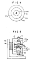
- Figure 4 is a schematic view showing an edge surface of an optical fiber, which should preferably be employed as the optical fiber 24 in the embodiment of Figure 1.
- the laser beam 11′ which has been condensed by the condensing lens 20 shown in Figure 1, impinges upon one edge of the optical fiber 24.
- a pinhole 24b through which the laser beam 11′ can pass, is formed in a core part 24a at said edge of the optical fiber 24.
- the pinhole 24b is located at the position at which an image of the light spot of the laser beam 11′ condensed by the condensing lens 20 shown in Figure 1 is formed.
- the optical fiber 24 is composed of the core part 24a, a cladding layer 24c, and a jacket layer 24d.
- the pinhole 24b is formed approximately at the center part of the edge surface of the core part 24a.
- the pinhole 24b is formed from a process wherein an aluminium layer is deposited by vacuum evaporation on the areas of the core part 24a and the cladding layer 24c in the edge surface of the optical fiber 24, upon which edge surface the laser beam 11′ condensed by the condensing lens 20 impinges, and only the part of the aluminium layer corresponding to the center part of the core part 24a is then removed by an etching technique.
- the diameter of the optical fiber 24 is approximately 125 ⁇ m, and the diameter of the core part 24a falls within the range of approximately 3 ⁇ m to approximately 10 ⁇ m.
- the diameter of the pinhole 24b is smaller than the diameter of the core part 24a and is, for example, approximately 1 ⁇ m.
- the aluminium layer is deposited by vacuum evaporation on the edge surface of the optical fiber 24, and the desired part of the aluminium layer is removed by the etching technique. Therefore, a pinhole having a desirable diameter smaller than the diameter of the core part 24a can be formed. Accordingly, a microscope image having good image quality, e.g. good resolution and contrast, can be obtained.
- the optical fiber 24 shown in Figure 4 may be modified in various ways.
- a layer of any of other metals may be deposited by vacuum evaporation on the edge surface of the optical fiber 24.
- the pinhole 24b need not necessarily be formed at the center part of the edge surface of the core part 24a, but may be formed at any position in the edge surface of the core part 24a. Therefore, a high accuracy is not required for the position at which the pinhole 24b is formed, and the pinhole 24b can be formed easily.
- a multi-mode optical fiber may be employed as the optical fiber 24.
- the multi-mode optical fiber is less expensive than the single-mode optical fiber. Therefore, when the multi-mode optical fiber is employed as the optical fiber 24, the manufacturing cost can be kept low.
- the optical fiber 24 shown in Figure 4 is applied to the confocal scanning microscope, which is of the transmission type.
- the optical fiber 24 shown in Figure 4 is also applicable to a confocal scanning microscope which is of the reflection type. Additionally, the optical fiber 24 shown in Figure 4 is applicable when the movable member 15 or the sample supporting member 22 is moved in the directions indicated by the double headed arrows X and Y, and the main scanning and the sub-scanning are thereby carried out.
- Figure 5 shows a second embodiment of the first confocal scanning microscope in accordance with the present invention, which is of the monochromatic transmission type.
- a light projecting optical means, a light receiving optical means, a light source, and a photodetector are supported together on a movable member. Therefore, the optical means can be kept simple, and the confocal scanning microscope can be kept small in size.
- similar elements are numbered with the same reference numerals with respect to Figures 1, 2, and 3.
- a laser diode 51 is employed as the laser beam source for producing the laser beam 11.
- the laser diode 51 is supported on the movable member 15.
- the laser beam 11 produced by the laser diode 51 directly impinges upon the light projecting optical means 18, which is supported on the movable member 15.
- the light projecting optical means 18 forms an image of the laser beam 11 as a small light spot at the point P on the sample 23.
- the laser beam 11′ which has passed through the sample 23, is condensed by the light receiving optical means 21, which is supported on the movable member 15.
- the condensed laser beam 11′ passes through an aperture pinhole 53 and then directly impinges upon a photodetector 52, which is supported on the movable member 15.
- an image of the condensed laser beam 11′ is formed at the photodetector 52.
- the two-dimensional scanning with the light spot formed at the point P is carried out in the same manner as that described above for the first embodiment.
- the output of the photodetector 52 is stored in a frame memory. In this manner, a signal can be obtained which represents the image information at every focusing plane within the range of movement of the sample 23 along the directions indicated by the double headed arrow Z, which is shown in Figure 3.
- Figure 6 shows a third embodiment of the confocal scanning microscope in accordance with the present invention.
- This embodiment is of the reflection type, wherein a light projecting optical means also serves as a light receiving optical means.
- similar elements are numbered with the same reference numerals with respect to Figures 1, 2, and 3. (This also applies to the drawings described later.)
- the laser beam 11 produced by the RGB laser 10 passes through the beam compressor 12, the distributed index lens 13, the single-mode optical fiber 14, and the light projecting optical means 18. An image of a small light spot is thereby formed at the point P on the sample 23.
- the laser beam 11", which has been reflected by the sample 23, is collimated by the objective lens 17 of the light projecting optical means 18, which also serves as the light receiving optical means 21 described above. Thereafter, the collimated laser beam 11" is condensed by the collimator lens 16, and the condensed laser beam 11" is guided back through the single-mode optical fiber 14.
- the laser beam 11" which has been guided back through the optical fiber 14, passes through the distributed index lens 13 and the beam compressor 12 and impinges upon a beam splitter 61.
- the laser beam 11" is reflected by the beam splitter 61 and then impinges upon a dichroic mirror 26. Only the blue light 11b is reflected by the dichroic mirror 26 and detected by the first photodetector 27. Thereafter, in the same manner as that described above for the first embodiment, the green light 11G and the red light 11R are detected by the second photodetector 29 and the third photodetector 31.
- the signals SB, SG, and SR generated by the photodetectors 27, 29, and 31 are stored on a frame memory. In this manner, signals can be obtained which represent the image information at every focusing plane within the range of movement of the sample 23 along the directions indicated by the double headed arrow Z, which is shown in Figure 3.
- Figure 7 shows a fourth embodiment of the confocal scanning microscope in accordance with the present invention, which is of the monochromatic reflection type.
- the optical means 18, the light source (the laser diode 51), and the photodetector 52 are supported together on the movable member 15.
- a semi-transparent mirror 79 is located in the optical means 18.
- a fifth embodiment of the confocal scanning microscope in accordance with the present invention which is constituted as a transmission type fluorescence microscope, will be described hereinbelow with reference to Figure 8.
- the major part of this scanning fluorescence microscope is constituted in the same manner as that in the first embodiment shown in Figure 1.
- an Ar laser 70 is employed as the laser beam source.
- a laser beam 71 having a wavelength of, for example, 488nm or 514.5nm is produced by the Ar laser 70.
- a sample 72 of a living organism is two-dimensionally scanned with the laser beam 71. Basically, the same scanning mechanism as that in the embodiment of Figure 1 is employed.
- a fluorescent probe such as Fluoroscein isothiocyanate (FITC), Texas Red, or Acridine Orange
- FITC Fluoroscein isothiocyanate
- Texas Red Texas Red
- Acridine Orange a fluorescent probe having intrinsic wavelengths.
- the fluorescence 73 and the laser beam 71 pass through the sample 72, are condensed by the light receiving optical means 21, and then enter the optical fiber 24.
- the fluorescence 73 and the laser beam 71 are guided through the optical fiber 24 and radiated out of the distributed index lens 25.
- the fluorescence 73 and the laser beam 71 which have been radiated out of the distributed index lens 25, impinge upon an interference filter 74.
- the interference filter 74 filters out the laser beam 71, and only the fluorescence 73 is detected by a photodetector 75.
- the sample 72 is two-dimensionally scanned with the laser beam 71, and an output S representing a two-dimensional enlarged image of the sample 72 is generated by the photodetector 75. Also, with this scanning fluorescence microscope, the fluorescence 73 produced from the inside of the sample 72 is detected, and therefore an image of the inside of the sample 72 can be formed.
- a sixth embodiment of the confocal scanning microscope in accordance with the present invention which is constituted as a reflection type fluorescence microscope, will be described hereinbelow with reference to Figure 9.
- the major part of this scanning fluorescence microscope is constituted in the same manner as that in the third embodiment shown in Figure 6.
- the Ar laser 70 is employed as the laser beam source.
- a fluorescent probe has been injected into the living organism sample 72.
- the sample 72 When the sample 72 is exposed to the laser beam 71, it produces the fluorescence 73.
- the fluorescence 73 and the laser beam 71 which has been reflected by the sample 72, pass through the sample 72, are condensed by the light receiving optical means 21, and then enter the optical fiber 14.
- the fluorescence 73 and the laser beam 71 are guided through the optical fiber 14 and radiated out of the distributed index lens 13.
- a dichroic mirror 76 is located between the distributed index lens 13 and the Ar laser 70.
- the fluorescence 73 and the laser beam 71 which have been radiated out of the distributed index lens 13, impinge upon the dichroic mirror 76.
- the dichroic mirror 76 reflects only the fluorescence 73 and guides it to the photodetector 75. In this manner, the fluorescence 73 is detected by the photodetector 75.
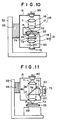
- a seventh embodiment of the confocal scanning microscope in accordance with the present invention which is constituted as a transmission type fluorescence microscope, will be described hereinbelow with reference to Figure 10.
- the major part of this scanning fluorescence microscope is constituted in the same manner as that in the second embodiment shown in Figure 5.
- a laser diode 80 is employed as the laser beam source.
- the laser diode 80 produces a laser beam 71, which has wavelengths falling within the stimulation wavelength range of the fluorescent substance which is formed by the fluorescent probe injected into the living organism sample 72.
- the same interference filter 74 as that employed in the fifth embodiment of Figure 8 is located in the light receiving optical means 21. Only the fluorescence 73 produced by the living organism sample 72 passes through the interference filter 74 and is detected by the photodetector 75.
- FIG. 11 An eighth embodiment of the confocal scanning microscope in accordance with the present invention, which is constituted as a reflection type fluorescence microscope, will be described hereinbelow with reference to Figure 11.
- the light projecting optical means 18, which is employed in the seventh embodiment shown in Figure 10 also serves as the light receiving optical means 21 described above.
- the same dichroic mirror 76 as that employed in the sixth embodiment of Figure 9 is located in the optical means 18.
- the fluorescence 73 which has been produced by the living organism sample 72, is reflected by the dichroic mirror 76 and thereby separated from the laser beam 71.
- the fluorescence 73, which has been reflected by the dichroic mirror 76 passes through the condensing lens 20 and the aperture pinhole 53, and is detected by the photodetector 75.
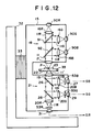
- a ninth embodiment of the confocal scanning microscope in accordance with the present invention will be described hereinbelow with reference to Figure 12.
- This confocal scanning microscope is of the transmission type and forms a color image.
- a red laser diode 90R, a green laser diode 90G, and a blue laser diode 90B are secured to the movable member 15, and produce a red laser beam 11R, a green laser beam 11G, and a blue laser beam 11B.
- the red laser beam 11R, the green laser beam 11G, and the blue laser beam 11B are respectively collimated by collimator lenses 16R, 16G, and 16B.
- the red laser beam 11R passes through dichroic mirrors 91 and 92.
- the green laser beam 11G is reflected by the dichroic mirror 91 and then passes through the dichroic mirror 92.
- the blue laser beam 11B is reflected by the dichroic mirror 92. In this manner, the red laser beam 11R, the green laser beam 11G, and the blue laser beam 11b are combined with one another, and combined laser beams 11 are obtained.
- the combined laser beams 11 are condensed by the objective lens 17, and an image of a small light spot of the combined laser beams 11 is formed at the point P on or in the sample, which is placed on the sample supporting member 22.
- the combined laser beams 11', which have passed through the sample 23, are collimated by the objective lens 19.
- the combined laser beams 11′ which have been collimated by the objective lens 19, impinge upon the dichroic mirror 26. Only the blue laser beam 11b is reflected by the dichroic mirror 26.
- the blue laser beam 11b which has been reflected by the dichroic mirror 26, is condensed by a condensing lens 20B, passes through an aperture pinhole 53B, and is then detected by the first photodetector 27.
- the combined laser beams 11′, which have passed through the dichroic mirror 26, impinge upon the dichroic mirror 28. Only the green laser beam 11G is reflected by the dichroic mirror 28.
- the green laser beam 11G which has been reflected by the dichroic mirror 28, is condensed by a condensing lens 20G, passes through an aperture pinhole 53G, and is then detected by the second photodetector 29.
- the red laser beam 11R which has passed through the dichroic mirror 28, is condensed by a condensing lens 20R, passes through an aperture pinhole 53R, and is then detected by the third photodetector 31.
- the photodetectors 27, 29, and 31 are constituted of photodiodes, or the like, and generate signals SB, SG, and SR, which represent the blue components, the green components, and the red components of an enlarged image of the sample 23.
- signals SB, SG, and SR represent the blue components, the green components, and the red components of an enlarged image of the sample 23.
- FIG. 13 A tenth embodiment of the confocal scanning microscope in accordance with the present invention will be described hereinbelow with reference to Figure 13.
- This confocal scanning microscope is of the reflection type and forms a color image.
- the red laser diode 90R, the green laser diode 90G, and the blue laser diode 90B are secured to the movable member 15.
- the light projecting optical means 18 is constituted basically in the same manner as that in the ninth embodiment of Figure 12.
- a beam splitter 61 is located between the dichroic mirror 92 and the objective lens 17. The combined laser beams 11 pass through the beam splitter 61.
- the combined laser beams 11", which have been reflected by the sample 23, are collimated by the objective lens 17 and then reflected by the beam splitter 61 to the light receiving optical means 21.
- the light receiving optical means 21 is constituted in the same manner as that in the ninth embodiment of Figure 12.
- the photodetectors 27, 29, and 31 generate the signals SB, SG, and SR, which represent the blue components, the green components, and the red components of an enlarged image of the sample 23.
- FIG. 14 is a plan view showing the scanning mechanism employed in this embodiment.
- a monochromatic light laser 100 produces a laser beam 11 having a single wavelength.
- the linear polarized laser beam 11 impinges in the P-polarized condition upon a film surface 101a of a polarization beam splitter 101 and passes therethrough.
- the laser beam 11, which has passed through the polarization beam splitter 101 then passes through a halfwave plate 102 for adjusting the plane of polarization.
- the laser beam 11, which has passed through the halfwave plate 102 is condensed by an entry lens 103 and enters a polarization plane keeping optical fiber 104.
- a PANDA type optical fiber may be employed as the polarization plane keeping optical fiber 104.
- Figure 16 shows the cross-sectional configuration of the PANDA type optical fiber 104.
- the optical fiber 104 is composed of a cladding part 104a and a core 104b which is located in the cladding. part 104a. Stress imparting parts 104c, 104c are formed on both sides of the core 104b.
- the halfwave plate 102 is rotated appropriately such that the orientation of the plane of polarization of the linear polarized laser beam 11 coincides with the directions indicated by the double headed arrow V in Figure 16, along which the stress imparting parts 104c, 104c stand in a line, or the directions indicated by the double headed arrow U in Figure 16, which directions are normal to the directions indicated by the double headed arrow V.
- the halfwave plate 102 is rotated appropriately such that the orientation of the plane of polarization of the linear polarized laser beam 11 coincides with the directions indicated by the double headed arrow U in Figure 16. In this manner, the linear polarized laser beam 11 is caused to impinge upon the optical fiber 104.
- One edge of the optical fiber 104 is secured to the movable member 15.
- the laser beam 11, which has been guided through the optical fiber 104, is radiated out of said edge of the optical fiber 104.
- said edge of the optical fiber 104 radiates the laser beam 11 like a point light source.
- the light projecting optical means 18, which is composed of the collimator lens 16 and the objective lens 17, is secured to the movable member 15. (The light projecting optical means 18 also serves as a light receiving optical means.)
- a quarter-wave plate 105 is located between the collimator lens 16 and the objective lens 17.
- the collimated laser beam 11 then passes through the quarter-wave plate 105 and is converted thereby into a circularly polarized laser beam.
- the collimated laser beam 11 is then condensed by the objective lens 17, and an image of a small light spot of the condensed laser beam 11 is formed at the point P on the sample 23 (i.e. on the surface of the sample 23 or in the inside of the sample 23).
- the sample 23 is placed on the sample supporting member 22.
- the laser beam 11 is reflected by the sample 23. At this time, the direction of rotation of the circularly polarized laser beam 11 is reversed.
- the laser beam 11 ⁇ which has thus been reflected by the sample 23, passes through the quarter-wave plate 105 and is converted thereby into a linear polarized laser beam 11 ⁇ having the plane of polarization, which is oriented in the direction normal to the orientation of the plane of polarization of the laser beam 11. Thereafter, the laser beam 11 ⁇ is condensed by the collimator lens 16 and impinges upon the polarization plane keeping optical fiber 104. At this time, the orientation of the plane of polarization of the laser beam 11 ⁇ coincides with the directions indicated by the double headed arrow V in Figure 16. The laser beam 11 ⁇ , which has been guided through the optical fiber 104, is radiated out of the edge of the optical fiber 104 and collimated by the entry lens 103.
- the laser beam 11 ⁇ which has thus been collimated by the entry lens 103, passes through the halfwave plate 102, impinges upon the film surface 101a of the polarization beam splitter 101 in the S-polarized condition, and is reflected by the film surface 101a.
- the laser beam 11 ⁇ which has thus been reflected by the film surface 101a, is condensed by a condensing lens 108, passes through an aperture pinhole 106, and is detected by the photodetector 75.
- the photodetector 75 generates a signal representing an enlarged image of the sample 23.
- a light isolator which is composed of the quarter-wave plate 105 and the polarization beam splitter 101. Therefore, the laser beam 11 ⁇ does not return to the laser 100, and a large amount of the laser beam 11 ⁇ can be guided to the photodetector 75. Also, the laser beam 11, which is reflected by the entry lens 103, the edge surface of the optical fiber 104, or the like, is prevented from impinging upon the photodetector 75. Therefore, a signal S having a high S/N ratio can be obtained.
- the movable member 15 is secured to one edge part of a tuning fork 110, which is placed horizontally, such that the optical axis of the optical means 18 extends vertically.
- a base part 110a of the tuning fork 110 is secured to the frame 32, and the tuning fork 110 can vibrate at a predetermined intrinsic frequency.
- An electromagnet 111 is located on the side outward from the other edge part of the tuning fork 110 in a slightly spaced relation thereto.
- a pulsed electric power source 112 applies a square-pulsed current having a frequency, which is equal to the intrinsic frequency of the tuning fork 110, to the electromagnet 111.
- a pulsed magnetic field acts on the other edge part of the tuning fork 110. Therefore, the tuning fork 110 vibrates at its intrinsic frequency.
- the movable member 15 secured to the tuning fork 110 is reciprocally moved at high speeds in the directions indicated by the arrow X in Figures 14 and 15 (i.e. horizontally). In this manner, the sample 23 is scanned with the light spot in the main scanning directions.
- an X movable stage 107X which is capable of reciprocally moving in the directions indicated by the arrow X, is located on the frame 32.
- a X movable stage 107Z which is capable of reciprocally moving in the directions indicated by the arrow Z (i.e. along the optical axis of the optical means 18), is located on the X movable stage 107X.
- a Y movable stage 107Y which is capable of reciprocally moving in the directions indicated by the arrow Y (which directions are normal to the directions indicated by the arrows X and Z), is located on the Z movable stage 107Z.
- the sample supporting member 22 is mounted on the Y movable stage 107Y.
- the X movable stage 107X, the Y movable stage 107Y, and the Z movable stage 107Z may be moved appropriately. In this manner, adjustment of the position of the sample 23 with respect to the optical means 18 (finding of the visual field and the focus adjustment) can be carried out.
- the Z movable stage 107Z is moved appropriately. In this manner, a signal S can be obtained which represent the image information at every focusing plane within the range of movement of the sample 23 along the directions indicated by the arrow Z.
- the scanning mechanisms employed in the aforesaid embodiments of the first confocal scanning microscope and the third scanning microscope in accordance with the present invention are also applicable when the scanning is to be carried out in apparatuses other than microscopes.
- the scanning mechanisms described above may be employed when the scanning is to be carried out during the writing of information in memories, the reading of information from memories, and the detection of video or audio signals from recording media.
Description
- This invention relates to a confocal scanning mechanism, such as a microscope, according to the pre-characterizing part of claim 1.
- Optical type scanning microscopes have heretofore been used. With the scanning microscope, a light beam is converged to a small light spot on a sample, and the sample is two-dimensionally scanned with the light spot. The light beam, which has passed through the sample during the scanning, the light beam, which has been reflected from the sample during the scanning, or the fluorescence, which is produced by the sample during the scanning, is detected by a photodetector. An enlarged image of the sample is thereby obtained.
- As one type of the scanning microscopes, a confocal scanning microscope has heretofore been proposed. With the confocal scanning microscope, a light beam is produced by a light source and is condensed to a light spot such that an image of the light spot is formed on a sample. Also, a point image of the light beam, which has been radiated out of the sample, is formed and detected by a photodetector. The confocal scanning microscope is advantageous in that no pinhole need to located on the surface of the sample.
- An example of the confocal scanning microscope is disclosed in Japanese Unexamined Patent Publication No. 62(1987)-217218. A microscope of the above-mentioned type is disclosed in DE-A-3 447 467.
- The conventional confocal scanning microscope utilizes one of the following scanning mechanisms:
- (1) a mechanism which two-dimensionally moves the sample supporting member, and
- (2) a mechanism which two-dimensionally deflects the light beam by a light deflector.
- However, the scanning mechanism described in (1) has the problem in that the sample flies out of its correct position when it is scanned quickly. With scanning microscopes, samples of living organisms are often observed. If the quick scanning cannot be carried out during the observation of a sample of a living organism, subtle movements of the sample cannot be found. Also, a need exists widely for the real-time recording of images of various other samples. If the quick scanning cannot be carried out, such a requirement cannot be satisfied.
- With the scanning mechanism described in (2), quick scanning can be achieved. However, the scanning mechanism has the drawback in that a light deflector, such as a galvanometer mirror or an acousto-optic light deflector (AOD), which is expensive must be used. Also, with the scanning mechanism described in (2), a light beam is deflected by a light deflector. As a result, the angle of incidence of the deflected light beam upon an objective lens of the light projecting optical means changes momentarily, and aberration is caused to occur. Therefore, the scanning mechanism described in (2) also has the problem in that it is difficult for the objective lens to be designed such that aberration can be eliminated.
- Particularly, in cases where an AOD is utilized, astigmatism occurs in the light beam radiated out of the AOD. Therefore, in such cases, a special correction lens must be used, and the optical means cannot be kept simple.
- According to DE-A-34 47 467, the light projecting lens (which serves also as light receiving lens) is supported on the distal end of a inovable arm. The lens receives a certain part of the light beam, dependent on its actual position.
- The object of the present invention is to provide a confocal scanning mechanism, such as a microscope, which enables quick scanning, which is simple, and which can be manufactured at a low cost.
- This object is achieved by the features of claim 1.
- The specific object of the present invention is to provide a scanning mechanism which is suitable for use in the scanning microscope.
- As will be understood from the specification, it should be noted that the term "moving a sample supporting member with respect to a movable member in sub-scanning directions" as used herein means movement of the sample supporting member relative to the movable member in the sub-scanning directions, and embraces both the cases wherein the sample supporting member is moved while the movable member is kept stationary with respect to the sub-scanning directions, and cases wherein the movable member is moved in the sub-scanning directions while the sample supporting member is kept stationary.
- The speed, at which the sample is scanned with the light spot in the sub-scanning directions, can be kept comparatively low. Therefore, even when the sample supporting member is moved in the sub-scanning direction in the manner described above, the sample does not fly out of its correct position.
- With the confocal scanning microscope in accordance with the present invention, the light beam is not deflected during the scanning. Therefore, only the light beam on the optical axis of the optical means need be taken into consideration during the designing of the optical means. Accordingly, the optical means can be designed easily.
- With the confocal scanning microscope in accordance with the present invention, the light projecting optical means and the light receiving optical means are supported together by the movable member, and the main scanning of the light spot is carried out by reciprocally moving the movable member. Therefore, the sample supporting member need not be moved quickly, and the sample is prevented from flying out of its correct position. Also, the quick scanning can be achieved.
- Also, as described above, with the confocal scanning microscope in accordance with the present invention, the light beam is not deflected during the scanning, and therefore the optical means can be designed easily. Additionally, no expensive light deflector, such as a galvanometer mirror or an AOD, need be used, and the configuration of the confocal scanning microscope can be kept simple. Therefore, the confocal scanning microscope in accordance with the present invention can be manufactured at a lower cost than the conventional confocal scanning microscope.
- As will be understood from the specification, it should be noted that the term "moving an optical means with respect to a sample supporting member" as used herein means movement of the optical means relative to the sample supporting member, and embraces the cases wherein the optical means is moved while the sample supporting member is kept stationary, cases wherein the sample supporting member is moved while the optical means is kept stationary, and cases wherein both the optical means and the sample supporting member are moved.
- With the scanning microscope in accordance with the present invention, a device, such as a piezo-electric device or an ultrasonic vibrator, which has a small operating force but is capable of quickly operating, can be utilized as the source for operating said moving member. Therefore, the quick scanning can be achieved. Accordingly, with the scanning microscope in accordance with the present invention, the time required for microscope images to be picked up can be kept markedly short.
-
- Figure 1 is a schematic front view showing a first embodiment of the confocal scanning microscope in accordance with the present invention,
- Figure 2 is a plan view showing the major part of the embodiment shown in Figure 1,
- Figure 3 is a side view showing the major part of the embodiment shown in Figure 1,
- Figure 4 is a schematic view showing an edge surface of an optical fiber, which may be employed in the embodiment of Figure 1,
- Figures 5, 6, 7, 8, 9, 10, 11, 12, 13, and 14 are schematic front views showing second, third, fourth, fifth, sixth, seventh, eighth, ninth, tenth, and eleventh embodiments of the confocal scanning microscope in accordance with the present invention,
- Figure 15 is a plan view showing a scanning mechanism employed in the eleventh embodiment of the confocal scanning microscope in accordance with the present invention, and
- Figure 16 is a sectional view showing a polarization plane keeping optical fiber employed in the eleventh embodiment of the confocal scanning microscope in accordance with the present invention.
- The present invention will hereinbelow be described in further detail with reference to the accompanying drawings.
- Figure 1 shows a first embodiment of the confocal scanning microscope in accordance with the present invention, which is of the transmission type. Figures 2 and 3 show a scanning mechanism employed in this embodiment. As illustrated in Figure 1, an
RGB laser 10 produces alaser beam 11 composed of red light, green light, and blue light. Abeam compressor 12 reduces the beam diameter of thelaser beam 11. Thelaser beam 11 then condensed by adistributed index lens 13 and impinges upon a single-modeoptical fiber 14. - One edge of the
optical fiber 14 is secured to amovable member 15. Thelaser beam 11, which has been guided through theoptical fiber 14, is radiated out of the edge of theoptical fiber 14, which is secured to themovable member 15. At this time, the edge of theoptical fiber 14 radiates thelaser beam 11 like a point light source. A light projectingoptical means 18 and a light receivingoptical means 21 are secured to themovable member 15 such that their optical axes align with each other. The light projectingoptical means 18 is composed of acollimator lens 16 and anobjective lens 17. The light receivingoptical means 21 is composed of anobjective lens 19 and a condensinglens 20. Also, asample supporting member 22, which is independent from themovable member 15, is located between the light projectingoptical means 18 and the light receivingoptical means 21. - The
laser beam 11 is collimated by thecollimator lens 16, and the collimatedlaser beam 11 is then condensed by theobjective lens 17. In this manner, an image of thecondensed laser beam 11 is formed as a small light spot at a point P on asample 23, which is placed on thesample supporting member 22. Alaser beam 11′, which has passed through thesample 23, is collimated by theobjective lens 19 of the light receivingoptical means 21, and the collimatedlaser beam 11′ is then condensed by the condensinglens 20. Thereafter, thecondensed laser beam 11′ impinges upon one edge of a single-modeoptical fiber 24 and enters theoptical fiber 24. The edge of theoptical fiber 24 is secured to themovable member 15, and the other edge thereof is connected to a distributedindex lens 25. Thelaser beam 11′, which has been guided through theoptical fiber 24, is radiated out of the other edge of theoptical fiber 24 and is collimated by the distributedindex lens 25. - The
laser beam 11′, which has been collimated by the distributedindex lens 25, impinges upon adichroic mirror 26. Only the blue light 11b is reflected by thedichroic mirror 26 and detected by afirst photodetector 27. Thelaser beam 11′, which has passed through thedichroic mirror 26, impinges upon adichroic mirror 28. Only the green light 11G is reflected by thedichroic mirror 28. The green light 11G is detected by asecond photodetector 29. Thelaser beam 11′ (i.e. the red light 11R), which has passed through thedichroic mirror 28, is reflected by amirror 30 and detected by athird photodetector 31. Thephotodetectors sample 23. - How the
sample 23 is two-dimensionally scanned with the light spot of thelaser beam 11, which is formed at the point P, will be described hereinbelow with reference to Figures 2 and 3. Figure 2 is a plan view showing themovable member 15 and the surrounding parts shown in Figure 1. Figure 3 is a right side view showing themovable member 15 and the surrounding parts shown in Figure 1. Themovable member 15 is secured to a laminated piezo-electric device 33, which is in turn secured to aframe 32. The laminated piezo-electric device 33 receives operating electric power from a piezo-electricdevice operating circuit 34 and reciprocally moves themovable member 15 at high speeds in the main scanning directions indicated by the double headed arrow X. By way of example, the frequency of the reciprocal movement is set as being 10kHz. In such cases, if the main scanning width is equal to 100µm, the main scanning speed will be equal to
optical fibers movable member 15 to move while thelaser beam 11 and thelaser beam 11′ are guided therethrough. - The
sample supporting member 22 is secured to a two-dimensionallymovable stage 35. The two-dimensionallymovable stage 35 is connected to amicrometer 38, which is in turn connected to apulse motor 37. Thepulse motor 37 receives an operating current from amotor operating circuit 36. The two-dimensionallymovable stage 35 is reciprocally moved by thepulse motor 37 in the sub-scanning directions indicated by the double headed arrow Y. In this manner, thesample supporting member 22 is moved with respect to themovable member 15, and thesample 23 is scanned with the light spot, which is formed at the point P, in the sub-scanning directions indicated by the double headed arrow Y. The sub-scanning directions are normal to the main scanning directions indicated by the double headed arrow X. By way of example, the time required for the sub-scanning is set as being 1/20 second. In such cases, if the sub-scanning width is equal to 100µm, the sub-scanning speed will be equal to
sample 23 does not fly out of its correct position when thesample supporting member 22 is moved. - In the manner described above, the
sample 23 is two-dimensionally scanned with a light spot formed at the point P. As a result, the time-serial signals SB, SG, and SR representing the two-dimensional image of thesample 23 are obtained. By way of example, the signals SB, SG, and SR are integrated with a predetermined period, and signals divided into picture elements are obtained. - In this embodiment, the two-dimensionally
movable stage 35 is also moved by apulse motor 40 in the directions indicated by the double headed arrow Z (i.e. along the optical axis of the light projectingoptical means 18 and the light receiving optical means 21), which directions are normal to the main scanning directions indicated by the double headed arrow X and the sub-scanning directions indicated by the double headed arrow Y. For this purpose, amotor operating circuit 39 feeds an operating current to thepulse motor 40. The two-dimensional scanning with the light spot formed at the point P is carried out each time the two-dimensionally movable.stage 35 is moved a predetermined distance along the directions indicated by the double headed arrow Z. In this manner, only the information at the focusing plane can be detected by thephotodetectors photodetectors sample 23 along the directions indicated by the double headed arrow Z. - A
control circuit 41 feeds synchronizing signals to the piezo-electricdevice operating circuit 34 and themotor operating circuits sample supporting member 22 in the directions indicated by the double headed arrow Z with each other. - The embodiment described above may be modified in various ways. For example, in the aforesaid embodiment, after the beam diameter of the
laser beam 11 is reduced by thebeam compressor 12, thelaser beam 11 is condensed by the distributedindex lens 13 and enters the single-modeoptical fiber 14. A microscope objective lens, or the like, may be employed in lieu of the distributedindex lens 13. Also, a multi-mode optical fiber provided with a pinhole, or the like, may be employed in lieu of the single-modeoptical fiber 14. - Also, a microscope objective lens, or the like, may be employed in lieu of the distributed
index lens 25, which serves as a condensing element on the side of the light receivingoptical means 21. A d.c. motor provided with an encoder may be employed in lieu of thepulse motor 37, which reciprocally moves thesample supporting member 22 secured to the two-dimensionallymovable stage 35 in the sub-scanning directions indicated by the double headed arrow Y. Instead of the sub-scannirg with the light spot, which is formed at the point P, being carried out by the movement of thesample supporting member 22, the sub-scanning with the light spot may be effected by moving themovable member 15. Additionally, instead of the laminated piezo-electric device 33 being used to move themovable member 15, a scanning technique utilizing a voice coil and natural oscillation of a solid with ultrasonic waves, or the like, may be utilized to move themovable member 15. - Figure 4 is a schematic view showing an edge surface of an optical fiber, which should preferably be employed as the
optical fiber 24 in the embodiment of Figure 1. As described above, thelaser beam 11′, which has been condensed by the condensinglens 20 shown in Figure 1, impinges upon one edge of theoptical fiber 24. A pinhole 24b, through which thelaser beam 11′ can pass, is formed in a core part 24a at said edge of theoptical fiber 24. The pinhole 24b is located at the position at which an image of the light spot of thelaser beam 11′ condensed by the condensinglens 20 shown in Figure 1 is formed. - Specifically, the
optical fiber 24 is composed of the core part 24a, acladding layer 24c, and ajacket layer 24d. The pinhole 24b is formed approximately at the center part of the edge surface of the core part 24a. The pinhole 24b is formed from a process wherein an aluminium layer is deposited by vacuum evaporation on the areas of the core part 24a and thecladding layer 24c in the edge surface of theoptical fiber 24, upon which edge surface thelaser beam 11′ condensed by the condensinglens 20 impinges, and only the part of the aluminium layer corresponding to the center part of the core part 24a is then removed by an etching technique. The diameter of theoptical fiber 24 is approximately 125µm, and the diameter of the core part 24a falls within the range of approximately 3µm to approximately 10µm. The diameter of the pinhole 24b is smaller than the diameter of the core part 24a and is, for example, approximately 1µm. In general, it is difficult for the diameters of core parts of the single-mode optical fibers to be made very small, and therefore the core parts have comparatively large diameters. In such cases, if a pinhole is formed over the whole area of the edge surface of the core part, a microscope image having good image quality cannot be obtained. In the embodiment described above, the aluminium layer is deposited by vacuum evaporation on the edge surface of theoptical fiber 24, and the desired part of the aluminium layer is removed by the etching technique. Therefore, a pinhole having a desirable diameter smaller than the diameter of the core part 24a can be formed. Accordingly, a microscope image having good image quality, e.g. good resolution and contrast, can be obtained. - The
optical fiber 24 shown in Figure 4 may be modified in various ways. For example, instead of the aluminium layer be deposited, a layer of any of other metals may be deposited by vacuum evaporation on the edge surface of theoptical fiber 24. Also, the pinhole 24b need not necessarily be formed at the center part of the edge surface of the core part 24a, but may be formed at any position in the edge surface of the core part 24a. Therefore, a high accuracy is not required for the position at which the pinhole 24b is formed, and the pinhole 24b can be formed easily. Additionally, instead of the single-mode optical fiber being used as theoptical fiber 24, a multi-mode optical fiber may be employed as theoptical fiber 24. The multi-mode optical fiber is less expensive than the single-mode optical fiber. Therefore, when the multi-mode optical fiber is employed as theoptical fiber 24, the manufacturing cost can be kept low. - In the embodiment described above, the
optical fiber 24 shown in Figure 4 is applied to the confocal scanning microscope, which is of the transmission type. Theoptical fiber 24 shown in Figure 4 is also applicable to a confocal scanning microscope which is of the reflection type. Additionally, theoptical fiber 24 shown in Figure 4 is applicable when themovable member 15 or thesample supporting member 22 is moved in the directions indicated by the double headed arrows X and Y, and the main scanning and the sub-scanning are thereby carried out. - Figure 5 shows a second embodiment of the first confocal scanning microscope in accordance with the present invention, which is of the monochromatic transmission type. In this embodiment, a light projecting optical means, a light receiving optical means, a light source, and a photodetector are supported together on a movable member. Therefore, the optical means can be kept simple, and the confocal scanning microscope can be kept small in size. In Figure 5, similar elements are numbered with the same reference numerals with respect to Figures 1, 2, and 3.
- With reference to Figure 5, a
laser diode 51 is employed as the laser beam source for producing thelaser beam 11. Thelaser diode 51 is supported on themovable member 15. Thelaser beam 11 produced by thelaser diode 51 directly impinges upon the light projectingoptical means 18, which is supported on themovable member 15. The light projecting optical means 18 forms an image of thelaser beam 11 as a small light spot at the point P on thesample 23. Thelaser beam 11′, which has passed through thesample 23, is condensed by the light receivingoptical means 21, which is supported on themovable member 15. Thecondensed laser beam 11′ passes through anaperture pinhole 53 and then directly impinges upon aphotodetector 52, which is supported on themovable member 15. In this manner, an image of thecondensed laser beam 11′ is formed at thephotodetector 52. In this embodiment, the two-dimensional scanning with the light spot formed at the point P is carried out in the same manner as that described above for the first embodiment. The output of thephotodetector 52 is stored in a frame memory. In this manner, a signal can be obtained which represents the image information at every focusing plane within the range of movement of thesample 23 along the directions indicated by the double headed arrow Z, which is shown in Figure 3. - Figure 6 shows a third embodiment of the confocal scanning microscope in accordance with the present invention. This embodiment is of the reflection type, wherein a light projecting optical means also serves as a light receiving optical means. In Figure 6, similar elements are numbered with the same reference numerals with respect to Figures 1, 2, and 3. (This also applies to the drawings described later.)
- With reference to Figure 6, in the same manner as that described above for the first embodiment, the
laser beam 11 produced by theRGB laser 10 passes through thebeam compressor 12, the distributedindex lens 13, the single-modeoptical fiber 14, and the light projectingoptical means 18. An image of a small light spot is thereby formed at the point P on thesample 23. Thelaser beam 11", which has been reflected by thesample 23, is collimated by theobjective lens 17 of the light projectingoptical means 18, which also serves as the light receivingoptical means 21 described above. Thereafter, the collimatedlaser beam 11" is condensed by thecollimator lens 16, and thecondensed laser beam 11" is guided back through the single-modeoptical fiber 14. Thelaser beam 11", which has been guided back through theoptical fiber 14, passes through the distributedindex lens 13 and thebeam compressor 12 and impinges upon abeam splitter 61. Thelaser beam 11" is reflected by thebeam splitter 61 and then impinges upon adichroic mirror 26. Only the blue light 11b is reflected by thedichroic mirror 26 and detected by thefirst photodetector 27. Thereafter, in the same manner as that described above for the first embodiment, the green light 11G and the red light 11R are detected by thesecond photodetector 29 and thethird photodetector 31. The signals SB, SG, and SR generated by thephotodetectors sample 23 along the directions indicated by the double headed arrow Z, which is shown in Figure 3. - Figure 7 shows a fourth embodiment of the confocal scanning microscope in accordance with the present invention, which is of the monochromatic reflection type. In this embodiment, like the second embodiment shown in Figure 5, the optical means 18, the light source (the laser diode 51), and the
photodetector 52 are supported together on themovable member 15. - In this reflection type confocal scanning microscope, the light projecting
optical means 18, which is employed in the second embodiment shown in Figure 5, also serves as the light receivingoptical means 21 described above. Also, asemi-transparent mirror 79 is located in theoptical means 18. Thelaser beam 11", which has been reflected by thesample 23, is reflected by thesemi-transparent mirror 79 and thereby separated from thelaser beam 11. Thelaser beam 11", which has been reflected by thesemi-transparent mirror 79, passes through the condensinglens 20 and theaperture pinhole 53, and is detected by thephotodetector 52. - A fifth embodiment of the confocal scanning microscope in accordance with the present invention, which is constituted as a transmission type fluorescence microscope, will be described hereinbelow with reference to Figure 8. The major part of this scanning fluorescence microscope is constituted in the same manner as that in the first embodiment shown in Figure 1. In this embodiment, an
Ar laser 70 is employed as the laser beam source. Alaser beam 71 having a wavelength of, for example, 488nm or 514.5nm is produced by theAr laser 70. Asample 72 of a living organism is two-dimensionally scanned with thelaser beam 71. Basically, the same scanning mechanism as that in the embodiment of Figure 1 is employed. - With reference to Figure 8, a fluorescent probe, such as Fluoroscein isothiocyanate (FITC), Texas Red, or Acridine Orange, has been injected cells of the
living organism sample 72. When such a fluorescent probe is exposed to thelaser beam 71, it produces thefluorescence 73 having intrinsic wavelengths. Thefluorescence 73 and thelaser beam 71 pass through thesample 72, are condensed by the light receivingoptical means 21, and then enter theoptical fiber 24. Thefluorescence 73 and thelaser beam 71 are guided through theoptical fiber 24 and radiated out of the distributedindex lens 25. Thefluorescence 73 and thelaser beam 71, which have been radiated out of the distributedindex lens 25, impinge upon aninterference filter 74. Theinterference filter 74 filters out thelaser beam 71, and only thefluorescence 73 is detected by aphotodetector 75. - With the scanning fluorescence microscope, the
sample 72 is two-dimensionally scanned with thelaser beam 71, and an output S representing a two-dimensional enlarged image of thesample 72 is generated by thephotodetector 75. Also, with this scanning fluorescence microscope, thefluorescence 73 produced from the inside of thesample 72 is detected, and therefore an image of the inside of thesample 72 can be formed. - A sixth embodiment of the confocal scanning microscope in accordance with the present invention, which is constituted as a reflection type fluorescence microscope, will be described hereinbelow with reference to Figure 9. The major part of this scanning fluorescence microscope is constituted in the same manner as that in the third embodiment shown in Figure 6. In this embodiment, like the fifth embodiment shown in Figure 8, the
Ar laser 70 is employed as the laser beam source. - With reference to Figure 9, a fluorescent probe has been injected into the living
organism sample 72. When thesample 72 is exposed to thelaser beam 71, it produces thefluorescence 73. Thefluorescence 73 and thelaser beam 71, which has been reflected by thesample 72, pass through thesample 72, are condensed by the light receivingoptical means 21, and then enter theoptical fiber 14. Thefluorescence 73 and thelaser beam 71 are guided through theoptical fiber 14 and radiated out of the distributedindex lens 13. Adichroic mirror 76 is located between the distributedindex lens 13 and theAr laser 70. Thefluorescence 73 and thelaser beam 71, which have been radiated out of the distributedindex lens 13, impinge upon thedichroic mirror 76. Thedichroic mirror 76 reflects only thefluorescence 73 and guides it to thephotodetector 75. In this manner, thefluorescence 73 is detected by thephotodetector 75. - A seventh embodiment of the confocal scanning microscope in accordance with the present invention, which is constituted as a transmission type fluorescence microscope, will be described hereinbelow with reference to Figure 10. The major part of this scanning fluorescence microscope is constituted in the same manner as that in the second embodiment shown in Figure 5. In this embodiment, a
laser diode 80 is employed as the laser beam source. Thelaser diode 80 produces alaser beam 71, which has wavelengths falling within the stimulation wavelength range of the fluorescent substance which is formed by the fluorescent probe injected into the livingorganism sample 72. - Also, in Figure 10, the
same interference filter 74 as that employed in the fifth embodiment of Figure 8 is located in the light receivingoptical means 21. Only thefluorescence 73 produced by the livingorganism sample 72 passes through theinterference filter 74 and is detected by thephotodetector 75. - An eighth embodiment of the confocal scanning microscope in accordance with the present invention, which is constituted as a reflection type fluorescence microscope, will be described hereinbelow with reference to Figure 11. In this embodiment, the light projecting
optical means 18, which is employed in the seventh embodiment shown in Figure 10, also serves as the light receivingoptical means 21 described above. Also, the samedichroic mirror 76 as that employed in the sixth embodiment of Figure 9 is located in theoptical means 18. Thefluorescence 73, which has been produced by the livingorganism sample 72, is reflected by thedichroic mirror 76 and thereby separated from thelaser beam 71. Thefluorescence 73, which has been reflected by thedichroic mirror 76, passes through the condensinglens 20 and theaperture pinhole 53, and is detected by thephotodetector 75. - A ninth embodiment of the confocal scanning microscope in accordance with the present invention will be described hereinbelow with reference to Figure 12. This confocal scanning microscope is of the transmission type and forms a color image. A
red laser diode 90R, agreen laser diode 90G, and ablue laser diode 90B are secured to themovable member 15, and produce a red laser beam 11R, a green laser beam 11G, and a blue laser beam 11B. The red laser beam 11R, the green laser beam 11G, and the blue laser beam 11B are respectively collimated bycollimator lenses dichroic mirrors dichroic mirror 91 and then passes through thedichroic mirror 92. The blue laser beam 11B is reflected by thedichroic mirror 92. In this manner, the red laser beam 11R, the green laser beam 11G, and the blue laser beam 11b are combined with one another, and combinedlaser beams 11 are obtained. - The combined
laser beams 11 are condensed by theobjective lens 17, and an image of a small light spot of the combinedlaser beams 11 is formed at the point P on or in the sample, which is placed on thesample supporting member 22. The combined laser beams 11', which have passed through thesample 23, are collimated by theobjective lens 19. - The combined
laser beams 11′, which have been collimated by theobjective lens 19, impinge upon thedichroic mirror 26. Only the blue laser beam 11b is reflected by thedichroic mirror 26. The blue laser beam 11b, which has been reflected by thedichroic mirror 26, is condensed by a condensing lens 20B, passes through an aperture pinhole 53B, and is then detected by thefirst photodetector 27. The combinedlaser beams 11′, which have passed through thedichroic mirror 26, impinge upon thedichroic mirror 28. Only the green laser beam 11G is reflected by thedichroic mirror 28. The green laser beam 11G, which has been reflected by thedichroic mirror 28, is condensed by a condensinglens 20G, passes through anaperture pinhole 53G, and is then detected by thesecond photodetector 29. Of the combinedlaser beams 11′, only the red laser beam 11R passes through thedichroic mirror 28. The red laser beam 11R, which has passed through thedichroic mirror 28, is condensed by a condensinglens 20R, passes through anaperture pinhole 53R, and is then detected by thethird photodetector 31. - The
photodetectors sample 23. In this embodiment, by way of example, the same scanning mechanism as that employed in the first embodiment of Figure 1 may be employed. - A tenth embodiment of the confocal scanning microscope in accordance with the present invention will be described hereinbelow with reference to Figure 13. This confocal scanning microscope is of the reflection type and forms a color image. In this embodiment, the
red laser diode 90R, thegreen laser diode 90G, and theblue laser diode 90B are secured to themovable member 15. - Also, the light projecting
optical means 18 is constituted basically in the same manner as that in the ninth embodiment of Figure 12. In this embodiment, abeam splitter 61 is located between thedichroic mirror 92 and theobjective lens 17. The combinedlaser beams 11 pass through thebeam splitter 61. - The combined
laser beams 11", which have been reflected by thesample 23, are collimated by theobjective lens 17 and then reflected by thebeam splitter 61 to the light receivingoptical means 21. The light receivingoptical means 21 is constituted in the same manner as that in the ninth embodiment of Figure 12. - In this embodiment, the
photodetectors sample 23. - An eleventh embodiment of the confocal scanning microscope in accordance with the present invention will be described hereinbelow with reference to Figure 14. This confocal scanning microscope is of the monochromatic reflection type. Figure 15 is a plan view showing the scanning mechanism employed in this embodiment. A
monochromatic light laser 100 produces alaser beam 11 having a single wavelength. The linearpolarized laser beam 11 impinges in the P-polarized condition upon a film surface 101a of apolarization beam splitter 101 and passes therethrough. Thelaser beam 11, which has passed through thepolarization beam splitter 101, then passes through ahalfwave plate 102 for adjusting the plane of polarization. Thelaser beam 11, which has passed through thehalfwave plate 102, is condensed by anentry lens 103 and enters a polarization plane keepingoptical fiber 104. - As the polarization plane keeping
optical fiber 104, a PANDA type optical fiber may be employed. Figure 16 shows the cross-sectional configuration of the PANDA typeoptical fiber 104. As illustrated in Figure 16, theoptical fiber 104 is composed of a cladding part 104a and a core 104b which is located in the cladding. part 104a.Stress imparting parts halfwave plate 102 is rotated appropriately such that the orientation of the plane of polarization of the linearpolarized laser beam 11 coincides with the directions indicated by the double headed arrow V in Figure 16, along which thestress imparting parts halfwave plate 102 is rotated appropriately such that the orientation of the plane of polarization of the linearpolarized laser beam 11 coincides with the directions indicated by the double headed arrow U in Figure 16. In this manner, the linearpolarized laser beam 11 is caused to impinge upon theoptical fiber 104. - One edge of the
optical fiber 104 is secured to themovable member 15. Thelaser beam 11, which has been guided through theoptical fiber 104, is radiated out of said edge of theoptical fiber 104. At this time, said edge of theoptical fiber 104 radiates thelaser beam 11 like a point light source. The light projectingoptical means 18, which is composed of thecollimator lens 16 and theobjective lens 17, is secured to themovable member 15. (The light projectingoptical means 18 also serves as a light receiving optical means.) A quarter-wave plate 105 is located between thecollimator lens 16 and theobjective lens 17. - The
laser beam 11, which has been radiated out of the aforesaid edge of theoptical fiber 104, is collimated by thecollimator lens 16. The collimatedlaser beam 11 then passes through the quarter-wave plate 105 and is converted thereby into a circularly polarized laser beam. The collimatedlaser beam 11 is then condensed by theobjective lens 17, and an image of a small light spot of thecondensed laser beam 11 is formed at the point P on the sample 23 (i.e. on the surface of thesample 23 or in the inside of the sample 23). Thesample 23 is placed on thesample supporting member 22. Thelaser beam 11 is reflected by thesample 23. At this time, the direction of rotation of the circularly polarizedlaser beam 11 is reversed. Thelaser beam 11˝, which has thus been reflected by thesample 23, passes through the quarter-wave plate 105 and is converted thereby into a linearpolarized laser beam 11˝ having the plane of polarization, which is oriented in the direction normal to the orientation of the plane of polarization of thelaser beam 11. Thereafter, thelaser beam 11˝ is condensed by thecollimator lens 16 and impinges upon the polarization plane keepingoptical fiber 104. At this time, the orientation of the plane of polarization of thelaser beam 11˝ coincides with the directions indicated by the double headed arrow V in Figure 16. Thelaser beam 11˝, which has been guided through theoptical fiber 104, is radiated out of the edge of theoptical fiber 104 and collimated by theentry lens 103. - Thereafter, the
laser beam 11˝, which has thus been collimated by theentry lens 103, passes through thehalfwave plate 102, impinges upon the film surface 101a of thepolarization beam splitter 101 in the S-polarized condition, and is reflected by the film surface 101a. Thelaser beam 11˝, which has thus been reflected by the film surface 101a, is condensed by a condensinglens 108, passes through anaperture pinhole 106, and is detected by thephotodetector 75. Thephotodetector 75 generates a signal representing an enlarged image of thesample 23. - As described above, a light isolator is provided which is composed of the quarter-
wave plate 105 and thepolarization beam splitter 101. Therefore, thelaser beam 11˝ does not return to thelaser 100, and a large amount of thelaser beam 11˝ can be guided to thephotodetector 75. Also, thelaser beam 11, which is reflected by theentry lens 103, the edge surface of theoptical fiber 104, or the like, is prevented from impinging upon thephotodetector 75. Therefore, a signal S having a high S/N ratio can be obtained. - How the
sample 23 is two-dimensionally scanned with the light spot of thelaser beam 11, which is formed at the point P, will be described hereinbelow with reference to Figures 14 and 15. Themovable member 15 is secured to one edge part of atuning fork 110, which is placed horizontally, such that the optical axis of the optical means 18 extends vertically. A base part 110a of thetuning fork 110 is secured to theframe 32, and thetuning fork 110 can vibrate at a predetermined intrinsic frequency. An electromagnet 111 is located on the side outward from the other edge part of thetuning fork 110 in a slightly spaced relation thereto. - A pulsed
electric power source 112 applies a square-pulsed current having a frequency, which is equal to the intrinsic frequency of thetuning fork 110, to the electromagnet 111. In this manner, a pulsed magnetic field acts on the other edge part of thetuning fork 110. Therefore, thetuning fork 110 vibrates at its intrinsic frequency. As a result, themovable member 15 secured to thetuning fork 110 is reciprocally moved at high speeds in the directions indicated by the arrow X in Figures 14 and 15 (i.e. horizontally). In this manner, thesample 23 is scanned with the light spot in the main scanning directions. - Also, an X movable stage 107X, which is capable of reciprocally moving in the directions indicated by the arrow X, is located on the
frame 32. A Xmovable stage 107Z, which is capable of reciprocally moving in the directions indicated by the arrow Z (i.e. along the optical axis of the optical means 18), is located on the X movable stage 107X. Also, a Ymovable stage 107Y, which is capable of reciprocally moving in the directions indicated by the arrow Y (which directions are normal to the directions indicated by the arrows X and Z), is located on the Zmovable stage 107Z. Thesample supporting member 22 is mounted on the Ymovable stage 107Y. When the main scanning with the light spot formed at the point P is carried out in the manner described above, the Ymovable stage 107Y is moved reciprocally. In this manner, the sub-scanning with the light spot formed at the point P can be effected. - Before the two-dimensional scanning with the light spot formed at the point P is carried out, the X movable stage 107X, the Y
movable stage 107Y, and the Zmovable stage 107Z may be moved appropriately. In this manner, adjustment of the position of thesample 23 with respect to the optical means 18 (finding of the visual field and the focus adjustment) can be carried out. - Also, each time the two-dimensional scanning with the light spot formed at the point P is carried out, the Z
movable stage 107Z is moved appropriately. In this manner, a signal S can be obtained which represent the image information at every focusing plane within the range of movement of thesample 23 along the directions indicated by the arrow Z. - Also, the scanning mechanisms employed in the aforesaid embodiments of the first confocal scanning microscope and the third scanning microscope in accordance with the present invention are also applicable when the scanning is to be carried out in apparatuses other than microscopes. For example, the scanning mechanisms described above may be employed when the scanning is to be carried out during the writing of information in memories, the reading of information from memories, and the detection of video or audio signals from recording media.
Claims (5)
- A confocal scanning mechanism comprising:i) a material supporting member (22) on which a material (23) to be scanned is supported,ii) a light source (10-14; 51, 80, 90R, G, B) which radiates a light beam (11, 71),iii) a light projecting optical means (18) with which said light beam (11, 71) is formed as a small light spot on said material (23) to be scanned,iv) a light receiving optical means (21) with which the light beam (11, 71) radiated out of said material (23) to be scanned is received, and the received light beam is condensed as a point image,v) a photodetector (52; 75; 24, 27, 29, 31) which detects said point image,vi) a movable member (15) which supports said light projecting optical means (18) and said light receiving optical means (21) together,vii) a main scanning means (33) which moves said movable member (15) such that said light spot scans said material (23) to be scanned, in a main scanning direction (X), andviii) a sub-scanning means (35-38) which moves said material supporting member (22) with respect to said movable member (15) in a sub-scanning direction (Y), which is approximately normal to said main scanning direction (X), whereby said material (23) to be scanned with said light spot moves in said sub-scanning direction (Y),characterized in thatsaid movable member (15) also supports said light source (51; 80; 90 R, G, B) and said photodetector (52; 75; 27, 29, 31).
- A mechanism as defined in claim 1 wherein said light projecting optical means (18) also serves as said light receiving optical means.
- A mechanism as defined in claim 1 or 2 wherein a means (39, 40) is provided which moves said material supporting member (22) in a direction (Z), which is normal to said main scanning direction (X) and said sub-scanning direction (Y).
- A mechanism as defined in at least one of claims 1 to 3 wherein said light source is a laser (10-14; 51; 80; 90 R, G, B).
- A mechanism as defined in any of claims 1 to 4, wherein the mechanism is part of a scanning microscope and the material to be scanned is a sample.
Priority Applications (1)
| Application Number | Priority Date | Filing Date | Title |
|---|---|---|---|
| EP95103875A EP0666487A2 (en) | 1989-09-22 | 1990-09-21 | Scanning microscope and scanning mechanism for the same |
Applications Claiming Priority (12)
| Application Number | Priority Date | Filing Date | Title |
|---|---|---|---|
| JP24694689 | 1989-09-22 | ||
| JP246946/89 | 1989-09-22 | ||
| JP1309498A JPH03168713A (en) | 1989-11-29 | 1989-11-29 | Scanning type microscope |
| JP309498/89 | 1989-11-29 | ||
| JP3177890A JPH03235909A (en) | 1990-02-13 | 1990-02-13 | Cofocal scanning type microscope |
| JP31779/90 | 1990-02-13 | ||
| JP31778/90 | 1990-02-13 | ||
| JP3177990 | 1990-02-13 | ||
| JP94654/90 | 1990-04-10 | ||
| JP9465490 | 1990-04-10 | ||
| JP143544/90 | 1990-06-01 | ||
| JP2143544A JP2663195B2 (en) | 1989-09-22 | 1990-06-01 | Confocal scanning microscope |
Related Child Applications (1)
| Application Number | Title | Priority Date | Filing Date |
|---|---|---|---|
| EP95103875.1 Division-Into | 1990-09-21 |
Publications (3)
| Publication Number | Publication Date |
|---|---|
| EP0418928A2 EP0418928A2 (en) | 1991-03-27 |
| EP0418928A3 EP0418928A3 (en) | 1992-07-15 |
| EP0418928B1 true EP0418928B1 (en) | 1996-05-01 |
Family
ID=27549616
Family Applications (1)
| Application Number | Title | Priority Date | Filing Date |
|---|---|---|---|
| EP90118213A Expired - Lifetime EP0418928B1 (en) | 1989-09-22 | 1990-09-21 | Scanning microscope and scanning mechanism for the same |
Country Status (3)
| Country | Link |
|---|---|
| US (1) | US5081350A (en) |
| EP (1) | EP0418928B1 (en) |
| DE (1) | DE69026780T2 (en) |
Cited By (1)
| Publication number | Priority date | Publication date | Assignee | Title |
|---|---|---|---|---|
| DE102020108333B3 (en) | 2020-03-26 | 2021-07-15 | Technische Universität Ilmenau | Method and device for the compensation of unsteady aberrations in the confocal measurement of a sample surface |
Families Citing this family (49)
| Publication number | Priority date | Publication date | Assignee | Title |
|---|---|---|---|---|
| CH697814B1 (en) * | 2001-01-26 | 2009-02-27 | Tecan Trading Ag | Optical system and method for exciting and measuring fluorescence on or in samples treated with fluorescent dyes. |
| JP2613118B2 (en) * | 1990-04-10 | 1997-05-21 | 富士写真フイルム株式会社 | Confocal scanning microscope |
| JPH0540224A (en) * | 1990-07-26 | 1993-02-19 | Fuji Photo Film Co Ltd | Scan type microscope |
| US5241364A (en) * | 1990-10-19 | 1993-08-31 | Fuji Photo Film Co., Ltd. | Confocal scanning type of phase contrast microscope and scanning microscope |
| JPH04157415A (en) * | 1990-10-20 | 1992-05-29 | Fuji Photo Film Co Ltd | Confocal scanning type interference microscope |
| US5179276A (en) * | 1991-03-27 | 1993-01-12 | Fuji Photo Film Co., Ltd. | Optical scanning type image pickup apparatus and optical scanning type microscope |
| US5218195A (en) * | 1991-06-25 | 1993-06-08 | Fuji Photo Film Co., Ltd. | Scanning microscope, scanning width detecting device, and magnification indicating apparatus |
| JPH0527177A (en) * | 1991-07-25 | 1993-02-05 | Fuji Photo Film Co Ltd | Scanning type microscope |
| US5248876A (en) * | 1992-04-21 | 1993-09-28 | International Business Machines Corporation | Tandem linear scanning confocal imaging system with focal volumes at different heights |
| WO1994010595A1 (en) * | 1992-10-23 | 1994-05-11 | Monash University | Confocal microscope and endoscope |
| GB9302799D0 (en) * | 1993-02-12 | 1993-03-31 | Medical Res Council | Detecting means for a scanning optical microscope |
| US5381224A (en) * | 1993-08-30 | 1995-01-10 | A. E. Dixon | Scanning laser imaging system |
| US5548113A (en) * | 1994-03-24 | 1996-08-20 | Trustees Of Boston University | Co-axial detection and illumination with shear force dithering in a near-field scanning optical microscope |
| US20050111089A1 (en) * | 1994-07-15 | 2005-05-26 | Baer Stephen C. | Superresolving microscopy apparatus |
| TW280928B (en) * | 1994-10-24 | 1996-07-11 | At & T Corp | |
| US5528050A (en) * | 1995-07-24 | 1996-06-18 | Molecular Dynamics, Inc. | Compact scan head with multiple scanning modalities |
| DE19702753C2 (en) * | 1997-01-27 | 2003-04-10 | Zeiss Carl Jena Gmbh | Laser Scanning Microscope |
| EP1935983B1 (en) * | 1997-05-05 | 2011-06-22 | ChemoMetec A/S | Method for determination of biological particles in blood |
| DE19834279C2 (en) * | 1998-07-30 | 2002-09-26 | Europ Lab Molekularbiolog | Compact single lens theta microscope |
| US6294775B1 (en) * | 1999-06-08 | 2001-09-25 | University Of Washington | Miniature image acquistion system using a scanning resonant waveguide |
| US6548796B1 (en) * | 1999-06-23 | 2003-04-15 | Regents Of The University Of Minnesota | Confocal macroscope |
| US20040224421A1 (en) * | 2000-06-15 | 2004-11-11 | Deweerd Herman | Bi-directional scanning method |
| JP2004505257A (en) * | 2000-07-27 | 2004-02-19 | ゼテティック・インスティチュート | Multiple source arrays for confocal and near-field microscopy |
| US7151632B2 (en) * | 2001-01-12 | 2006-12-19 | University Of Rochester | Apparatus for production of an inhomogeneously polarized optical beam for use in illumination and a method thereof |
| DE10120424B4 (en) * | 2001-04-26 | 2004-08-05 | Leica Microsystems Heidelberg Gmbh | Scanning microscope and decoupling element |
| US7633033B2 (en) | 2004-01-09 | 2009-12-15 | General Lasertronics Corporation | Color sensing for laser decoating |
| US20050231717A1 (en) * | 2004-04-16 | 2005-10-20 | Industrial Technology Research Institute | Fluorescence inspection spectrometer |
| US7139121B2 (en) * | 2004-06-18 | 2006-11-21 | Quickmate Company, Inc | Projection microscope |
| US7190514B2 (en) * | 2004-08-12 | 2007-03-13 | Yokogawa Electric Corporation | Confocal scanning microscope |
| US7680373B2 (en) * | 2006-09-13 | 2010-03-16 | University Of Washington | Temperature adjustment in scanning beam devices |
| GB0621585D0 (en) * | 2006-10-30 | 2006-12-06 | Secretary Trade Ind Brit | Confocal microscope |
| US7447415B2 (en) * | 2006-12-15 | 2008-11-04 | University Of Washington | Attaching optical fibers to actuator tubes with beads acting as spacers and adhesives |
| US7738762B2 (en) * | 2006-12-15 | 2010-06-15 | University Of Washington | Attaching optical fibers to actuator tubes with beads acting as spacers and adhesives |
| US8305432B2 (en) * | 2007-01-10 | 2012-11-06 | University Of Washington | Scanning beam device calibration |
| US8536483B2 (en) | 2007-03-22 | 2013-09-17 | General Lasertronics Corporation | Methods for stripping and modifying surfaces with laser-induced ablation |
| US7583872B2 (en) * | 2007-04-05 | 2009-09-01 | University Of Washington | Compact scanning fiber device |
| US7608842B2 (en) * | 2007-04-26 | 2009-10-27 | University Of Washington | Driving scanning fiber devices with variable frequency drive signals |
| US20080281159A1 (en) * | 2007-05-08 | 2008-11-13 | University Of Washington | Coordinating image acquisition among multiple endoscopes |
| US20080281207A1 (en) * | 2007-05-08 | 2008-11-13 | University Of Washington | Image acquisition through filtering in multiple endoscope systems |
| US8212884B2 (en) * | 2007-05-22 | 2012-07-03 | University Of Washington | Scanning beam device having different image acquisition modes |
| US20090008827A1 (en) * | 2007-07-05 | 2009-01-08 | General Lasertronics Corporation, A Corporation Of The State Of California | Aperture adapters for laser-based coating removal end-effector |
| US8437587B2 (en) * | 2007-07-25 | 2013-05-07 | University Of Washington | Actuating an optical fiber with a piezoelectric actuator and detecting voltages generated by the piezoelectric actuator |
| US7522813B1 (en) * | 2007-10-04 | 2009-04-21 | University Of Washington | Reducing distortion in scanning fiber devices |
| US8411922B2 (en) * | 2007-11-30 | 2013-04-02 | University Of Washington | Reducing noise in images acquired with a scanning beam device |
| US10112257B1 (en) | 2010-07-09 | 2018-10-30 | General Lasertronics Corporation | Coating ablating apparatus with coating removal detection |
| US9895771B2 (en) | 2012-02-28 | 2018-02-20 | General Lasertronics Corporation | Laser ablation for the environmentally beneficial removal of surface coatings |
| US10086597B2 (en) | 2014-01-21 | 2018-10-02 | General Lasertronics Corporation | Laser film debonding method |
| US11506877B2 (en) | 2016-11-10 | 2022-11-22 | The Trustees Of Columbia University In The City Of New York | Imaging instrument having objective axis and light sheet or light beam projector axis intersecting at less than 90 degrees |
| JP6677238B2 (en) | 2017-04-13 | 2020-04-08 | 横河電機株式会社 | Confocal scanner and confocal microscope |
Family Cites Families (8)
| Publication number | Priority date | Publication date | Assignee | Title |
|---|---|---|---|---|
| US4736110A (en) * | 1984-09-28 | 1988-04-05 | Nippon Jidoseigyo, Ltd. | Image pick-up apparatus |
| DE3447467A1 (en) * | 1984-12-27 | 1986-07-03 | United Kingdom Atomic Energy Authority, London | Scanning microscope |
| JPH0682173B2 (en) * | 1986-03-19 | 1994-10-19 | レーザーテック株式会社 | Transmission microscope imager |
| NL8700612A (en) * | 1987-03-13 | 1988-10-03 | Tno | CONFOCAL LASER SCANNING MICROSCOPE. |
| JPH0738046B2 (en) * | 1987-03-30 | 1995-04-26 | 新王子製紙株式会社 | Surface inspection device for semi-transparent sheet-like samples with internal structure |
| JPS63306413A (en) * | 1987-06-09 | 1988-12-14 | Olympus Optical Co Ltd | Scanning type optical microscope |
| US5032720A (en) * | 1988-04-21 | 1991-07-16 | White John G | Confocal imaging system |
| US5035476A (en) * | 1990-06-15 | 1991-07-30 | Hamamatsu Photonics K.K. | Confocal laser scanning transmission microscope |
-
1990
- 1990-09-21 DE DE69026780T patent/DE69026780T2/en not_active Expired - Fee Related
- 1990-09-21 EP EP90118213A patent/EP0418928B1/en not_active Expired - Lifetime
- 1990-09-24 US US07/587,122 patent/US5081350A/en not_active Expired - Lifetime
Cited By (1)
| Publication number | Priority date | Publication date | Assignee | Title |
|---|---|---|---|---|
| DE102020108333B3 (en) | 2020-03-26 | 2021-07-15 | Technische Universität Ilmenau | Method and device for the compensation of unsteady aberrations in the confocal measurement of a sample surface |
Also Published As
| Publication number | Publication date |
|---|---|
| DE69026780T2 (en) | 1996-11-07 |
| EP0418928A2 (en) | 1991-03-27 |
| US5081350A (en) | 1992-01-14 |
| DE69026780D1 (en) | 1996-06-05 |
| EP0418928A3 (en) | 1992-07-15 |
Similar Documents
| Publication | Publication Date | Title |
|---|---|---|
| EP0418928B1 (en) | Scanning microscope and scanning mechanism for the same | |
| US5260569A (en) | Scanning microscope and scanning mechanism | |
| JP2607804Y2 (en) | Confocal laser scanning microscope | |
| US5241364A (en) | Confocal scanning type of phase contrast microscope and scanning microscope | |
| US5719391A (en) | Fluorescence imaging system employing a macro scanning objective | |
| US5386112A (en) | Apparatus and method for transmitted-light and reflected-light imaging | |
| EP1245986B1 (en) | Confocal microscope | |
| US20050174425A1 (en) | Laser scanning confocal microscope with fibre bundle return | |
| JPH03291614A (en) | Confocal scanning type microscope | |
| US5506725A (en) | Transmission type confocal laser microscope | |
| EP0536273B1 (en) | Apparatus and method for transmitted-light and reflected-light imaging | |
| EP0666487A2 (en) | Scanning microscope and scanning mechanism for the same | |
| US5162648A (en) | Confocal scanning interference microscope using reference beam | |
| JP2663195B2 (en) | Confocal scanning microscope | |
| EP0718656B1 (en) | Transmission type confocal laser microscope | |
| JPH05224127A (en) | Confocal scanning type differential interfere microscope | |
| JPH03134609A (en) | Laser scanning type microscope | |
| JPH03172815A (en) | Cofocus scanning type microscope | |
| JP2660613B2 (en) | Confocal scanning microscope | |
| JP2613130B2 (en) | Confocal scanning phase contrast microscope | |
| JP2663194B2 (en) | Confocal scanning microscope | |
| JP2613129B2 (en) | Confocal scanning microscope | |
| JPH07199079A (en) | Microscopic photometry instrument | |
| JP3152130B2 (en) | Confocal light scanner | |
| JPH03131811A (en) | Confocal scanning type transmission microscope |
Legal Events
| Date | Code | Title | Description |
|---|---|---|---|
| PUAI | Public reference made under article 153(3) epc to a published international application that has entered the european phase |
Free format text: ORIGINAL CODE: 0009012 |
|
| AK | Designated contracting states |
Kind code of ref document: A2 Designated state(s): DE FR GB |
|
| PUAL | Search report despatched |
Free format text: ORIGINAL CODE: 0009013 |
|
| AK | Designated contracting states |
Kind code of ref document: A3 Designated state(s): DE FR GB |
|
| 17P | Request for examination filed |
Effective date: 19920922 |
|
| 17Q | First examination report despatched |
Effective date: 19940624 |
|
| GRAH | Despatch of communication of intention to grant a patent |
Free format text: ORIGINAL CODE: EPIDOS IGRA |
|
| GRAA | (expected) grant |
Free format text: ORIGINAL CODE: 0009210 |
|
| AK | Designated contracting states |
Kind code of ref document: B1 Designated state(s): DE FR GB |
|
| XX | Miscellaneous (additional remarks) |
Free format text: TEILANMELDUNG 95103875.1 EINGEREICHT AM 21/09/90. |
|
| REF | Corresponds to: |
Ref document number: 69026780 Country of ref document: DE Date of ref document: 19960605 |
|
| ET | Fr: translation filed | ||
| PLBE | No opposition filed within time limit |
Free format text: ORIGINAL CODE: 0009261 |
|
| STAA | Information on the status of an ep patent application or granted ep patent |
Free format text: STATUS: NO OPPOSITION FILED WITHIN TIME LIMIT |
|
| 26N | No opposition filed | ||
| REG | Reference to a national code |
Ref country code: GB Ref legal event code: IF02 |
|
| REG | Reference to a national code |
Ref country code: GB Ref legal event code: 732E |
|
| REG | Reference to a national code |
Ref country code: FR Ref legal event code: TP Ref country code: FR Ref legal event code: CD |
|
| PGFP | Annual fee paid to national office [announced via postgrant information from national office to epo] |
Ref country code: FR Payment date: 20080915 Year of fee payment: 19 |
|
| PGFP | Annual fee paid to national office [announced via postgrant information from national office to epo] |
Ref country code: GB Payment date: 20080924 Year of fee payment: 19 |
|
| PGFP | Annual fee paid to national office [announced via postgrant information from national office to epo] |
Ref country code: DE Payment date: 20081002 Year of fee payment: 19 |
|
| GBPC | Gb: european patent ceased through non-payment of renewal fee |
Effective date: 20090921 |
|
| REG | Reference to a national code |
Ref country code: FR Ref legal event code: ST Effective date: 20100531 |
|
| PG25 | Lapsed in a contracting state [announced via postgrant information from national office to epo] |
Ref country code: DE Free format text: LAPSE BECAUSE OF NON-PAYMENT OF DUE FEES Effective date: 20100401 Ref country code: FR Free format text: LAPSE BECAUSE OF NON-PAYMENT OF DUE FEES Effective date: 20090930 |
|
| PG25 | Lapsed in a contracting state [announced via postgrant information from national office to epo] |
Ref country code: GB Free format text: LAPSE BECAUSE OF NON-PAYMENT OF DUE FEES Effective date: 20090921 |