EP0283909B1 - Hochdruckreinigungsgerät - Google Patents
Hochdruckreinigungsgerät Download PDFInfo
- Publication number
- EP0283909B1 EP0283909B1 EP88104133A EP88104133A EP0283909B1 EP 0283909 B1 EP0283909 B1 EP 0283909B1 EP 88104133 A EP88104133 A EP 88104133A EP 88104133 A EP88104133 A EP 88104133A EP 0283909 B1 EP0283909 B1 EP 0283909B1
- Authority
- EP
- European Patent Office
- Prior art keywords
- pressure
- pump
- housing
- pressure pump
- shaft
- Prior art date
- Legal status (The legal status is an assumption and is not a legal conclusion. Google has not performed a legal analysis and makes no representation as to the accuracy of the status listed.)
- Expired - Lifetime
Links
- 238000004140 cleaning Methods 0.000 title claims description 20
- 238000002485 combustion reaction Methods 0.000 claims description 16
- 230000005540 biological transmission Effects 0.000 claims description 12
- 239000000446 fuel Substances 0.000 claims description 9
- 239000007921 spray Substances 0.000 claims description 3
- 239000012530 fluid Substances 0.000 claims description 2
- 238000010276 construction Methods 0.000 description 4
- 239000007788 liquid Substances 0.000 description 4
- 239000007858 starting material Substances 0.000 description 2
- 230000006835 compression Effects 0.000 description 1
- 238000007906 compression Methods 0.000 description 1
- 230000002349 favourable effect Effects 0.000 description 1
- 238000002347 injection Methods 0.000 description 1
- 239000007924 injection Substances 0.000 description 1
- 230000007257 malfunction Effects 0.000 description 1
- 238000000034 method Methods 0.000 description 1
- 125000006850 spacer group Chemical group 0.000 description 1
Images
Classifications
-
- B—PERFORMING OPERATIONS; TRANSPORTING
- B08—CLEANING
- B08B—CLEANING IN GENERAL; PREVENTION OF FOULING IN GENERAL
- B08B3/00—Cleaning by methods involving the use or presence of liquid or steam
-
- B—PERFORMING OPERATIONS; TRANSPORTING
- B08—CLEANING
- B08B—CLEANING IN GENERAL; PREVENTION OF FOULING IN GENERAL
- B08B3/00—Cleaning by methods involving the use or presence of liquid or steam
- B08B3/02—Cleaning by the force of jets or sprays
- B08B3/026—Cleaning by making use of hand-held spray guns; Fluid preparations therefor
-
- F—MECHANICAL ENGINEERING; LIGHTING; HEATING; WEAPONS; BLASTING
- F24—HEATING; RANGES; VENTILATING
- F24H—FLUID HEATERS, e.g. WATER OR AIR HEATERS, HAVING HEAT-GENERATING MEANS, e.g. HEAT PUMPS, IN GENERAL
- F24H1/00—Water heaters, e.g. boilers, continuous-flow heaters or water-storage heaters
- F24H1/08—Packaged or self-contained boilers, i.e. water heaters with control devices and pump in a single unit
-
- B—PERFORMING OPERATIONS; TRANSPORTING
- B08—CLEANING
- B08B—CLEANING IN GENERAL; PREVENTION OF FOULING IN GENERAL
- B08B2203/00—Details of cleaning machines or methods involving the use or presence of liquid or steam
- B08B2203/007—Heating the liquid
-
- B—PERFORMING OPERATIONS; TRANSPORTING
- B08—CLEANING
- B08B—CLEANING IN GENERAL; PREVENTION OF FOULING IN GENERAL
- B08B2203/00—Details of cleaning machines or methods involving the use or presence of liquid or steam
- B08B2203/02—Details of machines or methods for cleaning by the force of jets or sprays
- B08B2203/0217—Use of a detergent in high pressure cleaners; arrangements for supplying the same
Definitions
- the invention relates to a high-pressure cleaning device with an internal combustion engine, which drives a high-pressure pump via transmission means, via which a cleaning liquid is delivered under pressure to a spray device.
- a high-pressure cleaning device with an internal combustion engine, which drives a high-pressure pump via transmission means, via which a cleaning liquid is delivered under pressure to a spray device.
- Such a device is known from US-A 4 047 665.
- FR-A 2 473 912 describes a high-pressure cleaning device in which a high-pressure pump driven by an electric motor is flanged directly to the electric motor, so that the motor shaft of the electric motor projects into the housing of the high-pressure pump.
- a high-pressure cleaning device of the type described in the introduction in that the high-pressure pump is arranged on the motor in such a way that the output shaft of the internal combustion engine or an extension thereof projects into the housing of the high-pressure pump in such a way that a space is present between the internal combustion engine and the pump housing and that in this space a pulley connected to the output shaft of the engine is arranged, which drives an electric generator via a transmission belt to supply the engine with electrical ignition energy.
- the main power sensor namely the high-pressure cleaning pump, is connected directly to the output shaft of the internal combustion engine in this construction, so that the power can be transmitted directly to the high-pressure pump without the interposition of belt transmissions. This results in a particularly space-saving construction and a lossless and robust construction.
- the high-pressure pump is plugged directly onto the output shaft, it is still possible to drive an electrical generator.
- This is done by the pulley arranged in the space between the high-pressure pump and the internal combustion engine on the output shaft, which hardly increases the dimensions of the overall very compact unit and which thus also enables the drive of a generator in a space-saving manner, which supplies the engine with electrical ignition energy after starting , so that a battery can be dispensed with.
- the kinetic energy required for the generator is only a small part of the energy required for the high-pressure pump, so that the use of a belt drive in the generator is not disadvantageous.
- the shaft of the generator directly drives a fan for a burner and a fuel pump. It is thus possible to heat the high-pressure cleaning fluid in a burner, the electrical energy required for igniting the burner also being supplied by the generator. A single belt drive is therefore sufficient to enable all power transmissions from the engine to the driven units.
- the construction becomes particularly compact if the fan and the fuel pump are held on the generator housing, preferably by flanging directly on.
- the high-pressure pump is designed as a swash plate pump, that a swash plate shaft surrounding the output shaft of the motor is guided out of the housing of the high-pressure pump in a sealed manner and is sealed off from the output shaft.
- the inside of the high-pressure pump can be filled with oil, which nevertheless cannot penetrate into the motor housing.
- the pulley is held on the swash plate shaft, that is to say that the swash plate shaft protruding from the high-pressure pump housing carries in its area protruding from the housing the pulley which is connected to it in a rotationally fixed manner.
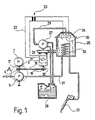
- the high-pressure cleaning device shown in the drawing is driven by an engine 1 which is designed as an internal combustion engine, for example a gasoline or a diesel engine.
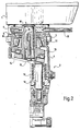
- This has a drive shaft 2 protruding from its housing, onto which a high-pressure pump 3 is attached (FIG. 2).
- These High-pressure pump 3 comprises a housing 4, which is fastened to the housing of the motor 1 via spacer pins 5 such that an intermediate space 6 is formed between the housing of the motor 1 and the housing 4 of the high-pressure pump 3, through which the drive shaft 2 of the motor 1 passes.
- a swash plate shaft 7 is arranged on the drive shaft 2 of the motor 1 immersed in the housing, which is rotatably pushed onto the drive shaft 2 and so protrudes from an opening 8 of the housing 4 that it drives the drive shaft 2 to surrounds the housing of the motor 1.
- the swash plate shaft 7 is fixed in the axial direction on the drive shaft 2 by means of a screw 9 and is sealed off from the drive shaft 2 by an annular seal 10 at its free end.
- a ring seal 11 which surrounds the swash plate shaft 7 and which seals the inside of the housing 4 to the outside, is arranged in the opening 8.
- the swash plate shaft 7 is rotatably mounted in the interior of the housing 4 by means of a ball bearing 12 and carries a pressure ring 14 on its inclined swash plate 13, which is also rotatably mounted relative to the plate 13 via a ball bearing.
- a plurality of axial pistons 16 of the high-pressure pump are pressed onto the pressure ring 14 via compression springs 15, only a single one being shown in the drawing of a plurality of pistons.
- the axial piston 16 pumps a liquid from a suction line under high pressure into a pressure line in a manner known per se and therefore not detailed.
- a pulley 17 is arranged on the swash plate shaft 7 in a manner fixed against relative rotation, over which a transmission belt 18 runs.
- the transmission belt 18 leads to a further pulley 19, which is held on the drive shaft 20 of an electric generator 21 in a rotationally fixed manner.
- an electric generator 21 When it rotates via lines 22 and a transformer 23, it supplies an ignition voltage to ignition electrodes 24 of an oil burner 25.
- the generator can supply the ignition voltage for the spark plugs of the engine; the line connections required for this are not specifically shown in the drawing.
- a blower 26 is flanged directly to the generator 21, which is also driven by the drive shaft 20 and supplies an air flow to the oil burner 25.
- the drive shaft 20 also drives a fuel pump 27, which supplies fuel from a storage container 28 via a line 29 to an injection nozzle 30 of the oil burner 25.
- the fuel pump 27 can be flanged directly to the blower 26, so that the generator, blower and fuel pump form a unit driven by a common drive shaft 20, the drive shaft 20 being driven by the pulley 17 via the transmission belt 18.
- the cleaning medium conveyed by the high-pressure pump 3 is fed via a line 31 to a heat exchanger 32 in the oil burner 25, so that the cleaning liquid is heated there.
- the heated cleaning liquid is then directed onto the surface to be cleaned by the operator via a hand spray gun 33.
- the internal combustion engine 1 is started by an operator using a mechanical starter, for example a reversing starter. No battery is required for this process. As soon as the engine is running, most of its power is transferred to the high-pressure pump, a small part drives the generator, the blower and the fuel pump.
- the overall result is an extremely compact design, in which all driven units, including the drive motor, are combined in two blocks, which are coupled to one another via a transmission belt.
Landscapes
- Engineering & Computer Science (AREA)
- Physics & Mathematics (AREA)
- Thermal Sciences (AREA)
- Chemical & Material Sciences (AREA)
- Combustion & Propulsion (AREA)
- Mechanical Engineering (AREA)
- General Engineering & Computer Science (AREA)
- Cleaning By Liquid Or Steam (AREA)
Description
- Die Erfindung betrifft ein Hochdruckreinigungsgerät mit einem Verbrennungsmotor, der über Getriebemittel eine Hochdruckpumpe antreibt, über welche eine Reinigungsflüssigkeit unter Druck an eine Spritzeinrichtung abgegeben wird. Ein derartiges Gerät ist aus der US-A 4 047 665 bekannt.
- Es sind auch andere Hochdruckreinigungsanlagen bekannt, die durch einen Benzin- oder Dieselmotor angetrieben werden. Bei diesen bekannten Vorrichtungen wird eine Hochdruckpumpe üblicherweise über einen Riemenantrieb von dem Verbrennungsmotor angetrieben. Die Leistungsübertragung vom Verbrennungsmotor auf die Hochdruckpumpe über einen Riemenantrieb benötigt nicht nur viel Platz, sondern es ergeben sich dadurch Leistungsverluste und Störanfälligkeiten, die unerwünscht sind. Außerdem ist es bei den bekannten Geräten dieser Art notwendig, eine Batterie zu verwenden, aie über eine vom Antriebsmotor angetriebene Lichtmaschine getrieben wird. Auch dadurch wird ein solches Gerät schwer, kompliziert im Aufbau und störanfällig.
- In der FR-A 2 473 912 wird ein Hochdruckreinigungsgerät beschrieben, bei dem eine über einen Elektromotor getriebene Hochdruckpumpe unmittelbar an den Elektromotor angeflanscht ist, so daß die Motorwelle des Elektromotors in das Gehäuse der Hochdruckpumpe hineinragt. Es besteht bei der Verwendung eines Elektromotors natürlich keinerlei Notwendigkeit, eine Zündspannung zu erzeugen, die andererseits beim Betrieb von Verbrennungsmotoren benötigt wird.
- Es ist Aufgabe der Erfindung, ein durch einen Verbrennungsmotor angetriebenes Hochdruckreinigungsgerät der eingangs beschriebenen Art so zu verbessern, daß eine besonders günstige Kraftübertragung zur Hochdruckpumpe gewährleistet wird und auf eine Batterie verzichtet werden kann.
- Diese Aufgabe wird bei einem Hochdruckreinigungsgerät der eingangs beschriebenen Art erfindungsgemäß dadurch gelöst, daß die Hochdruckpumpe am Motor derart angeordnet ist, daß die Ausgangswelle des Verbrennungsmotors oder eine Verlängerung derselben in das Gehäuse der Hochdruckpumpe hineinragt, daß zwischen dem Verbrennungsmotor und dem Pumpengehäuse ein Zwischenraum vorhanden ist und daß in diesem Zwischenraum eine drehfest mit der Ausgangswelle des Motors verbundene Riemenscheibe angeordnet ist, die über einen Transmissionsriemen einen elektrischen Generator zur Versorgung des Motors mit elektrischer Zündenergie antreibt.
- Der Hauptleistungsaufnehmer, nämlich die Hochdruckreinigungspumpe, ist bei dieser Konstruktion unmittelbar mit der Ausgangswelle des Verbrennungsmotors verbunden, so daß ohne Zwischenschaltung von Riemenübertragungen die Leistung unmittelbar auf die Hochdruckpumpe übertragen werden kann. Es ergibt sich dadurch ein besonders platzsparender Aufbau und eine verlusttreie und robuste Konstruktion.
- Aufgrund des unmittelbaren Aufsteckens der Hochdruckpumpe auf die Ausgangswelle besteht noch die Möglichkeit, einen elektrischen Generator anzutreiben. Dies erfolgt durch die im Zwischenraum zwischen Hochdruckpumpe und Verbrennungsmotor auf der Ausgangswelle angeordnete Riemenscheibe, die die Abmessungen der insgesamt sehr kompakten Baueinheit kaum vergrößert und die damit in platzsparender Weise zusätzlich noch den Antrieb eines Generators ermöglicht, der den Motor nach dem Start mit elektrischer Zündenergie versorgt, so daß auf eine Batterie verzichtet werden kann. Die für den Generator benötigte Bewegungsenergie ist nur ein kleiner Teil der für die Hochdruckpumpe benötigten Energie, so daß die Verwendung eines Riemenantriebes beim Generator nicht nachteilig ist.
- Bei einer bevorzugten Ausgestaltung der Erfindung ist vorgesehen, daß die Welle des Generators unmittelbar ein Gebläse für einen Brenner und eine Brennstoffpumpe antreibt. Es ist damit möglich, die Hochdruckreinigungsflüssigkeit in einem Brenner zu beheizen, wobei die dafür benötigte elektrische Energie zur Zündung des Brenners ebenfalls vom Generator geliefert wird. Es genügt also ein einziger Riemenantrieb, um alle Kraftübertragungen vom Motor auf die angetriebenen Aggregate zu ermöglichen.
- Besonders kompakt wird der Aufbau, wenn das Gebläse und die Brennstoffpumpe am Generatorgehäuse gehalten sind, vorzugsweise durch unmittelbares Anflanschen.
- Bei einem bevorzugten Ausführungsbeispiel ist vorgesehen, daß die Hochdruckpumpe als Taumelscheibenpumpe ausgebildet ist, daß ein die Ausgangswelle des Motors umgebender Taumelscheibenschaft abgedichtet aus dem Gehäuse der Hochdruckpumpe herausgeführt ist und gegeniber der Augsgangswelle abgedichtet ist. Auf diese Weise kann das Innere der Hochdruckpumpe mit Öl gefüllt sein, welches trotzdem nicht in das Motorgehäuse eindringen kann.
- Es kann vorgesehen sein, daß die Riemenscheibe auf dem Taumelscheibenschaft gehalten ist, das heißt, der aus dem Hochdruckpumpengehäuse herausragende Taumelscheibenschaft trägt in seinem aus dem Gehäuse herausstehenden Bereich die Riemenscheibe, die mit ihm drehfest verbunden ist.
- Die nachfolgende Beschreibung bevorzugter Ausführungsformen der Erfindung dient im Zusammenhang mit der Zeichnung der näheren Erläuterung. Es zeigen:
- Fig. 1 eine schematische Ansicht eines Hochdruckreinigungsgerätes mit einem Verbrennungsmotor als Antriebsaggregat und
- Fig. 2 eine Teilschnittdarstellung einer an einem Verbrennungsmotor gehaltenen Hochdruckpumpe mit zwischengeschalteter Riemenscheibe.
- Das in der Zeichnung dargestellte Hochdruckreinigungsgerät wird von einem Motor 1 angetrieben, der als Verbrennungsmotor ausgebildet ist, es handelt sich beispielsweise um einen Benzin- oder einen Dieselmotor. Dieser weist eine aus seinem Gehäuse hervortretende Antriebswelle 2 auf, auf die eine Hochdruckpumpe 3 aufgesteckt ist (Figur 2). Diese Hochdruckpumpe 3 umfaßt ein Gehäuse 4, welches über Abstandszapfen 5 so am Gehäuse des Motors 1 befestigt ist, daß zwischen dem Gehäuse des Motors 1 und dem Gehäuse 4 der Hochdruckpumpe 3 ein Zwischenraum 6 ausgebildet ist, durch den die Antriebswelle 2 des Motors 1 hindurchtritt.
- Im Innern des Gehäuses 4 der Hochdruckpumpe 3 ist auf der in das Gehäuseinnere eintauchenden Antriebswelle 2 des Motors 1 ein Taumelscheibenschaft 7 angeordnet, der drehfest auf die Antriebswelle 2 aufgeschoben ist und so aus einer Öffnung 8 des Gehäuses 4 herausragt, daß er die Antriebswelle 2 bis zum Gehäuse des Motors 1 hin umgibt. Der Taumelscheibenschaft 7 ist mittels einer Schraube 9 in axialer Richtung an der Antriebswelle 2 festgelegt und durch eine Ringdichtung 10 an seinem freien Ende gegenüber der Antriebswelle 2 abgedichtet. Außerdem ist in der Öffnung 8 eine den Taumelscheibenschaft 7 umgebende Ringdichtung 11 angeordnet, welche das Innere des Gehäuses 4 nach außen hin abdichtet.
- Der Taumelscheibenschaft 7 ist mittels eines Kugellagers 12 drehbar im Inneren des Gehäuses 4 gelagert und trägt an seiner schräggestellten Taumelscheibe 13 einen Andruckring 14, der ebenfalls über ein Kugellager drehbar gegenüber der Scheibe 13 gelagert ist. An dem Andruckring 14 werden über Druckfedern 15 mehrere Axialkolben 16 der Hochdruckpumpe angedrückt, wobei in der Zeichnung von mehreren Kolben nur ein einziger dargestellt ist. Der Axialkolben 16 pumpt in an sich bekannter und daher nicht näher ausgeführter Weise eine Flüssigkeit aus einer Saugleitung unter hohem Druck in eine Druckleitung.
- In dem Zwischenraum 6 ist auf dem Taumelscheibenschaft 7 drehfest eine Riemenscheibe 17 angeordnet, über die ein Transmissionsriemen 18 läuft.
- Wie aus Figur 1 ersichtlich wird, führt der Transmissionsriemen 18 zu einer weiteren Riemenscheibe 19, die drehfest auf der Antriebswelle 20 eines elektrischen Generators 21 gehalten ist. Dieser liefert bei Drehung über Leitungen 22 und einen Transformator 23 eine Zündspannung zu Zündelektroden 24 eines Ölbrenners 25. Außerdem kann der Generator die Zündspannung für die Zindkerzen des Motors liefern, die dazu notwendigen Leitungsverbindungen sind in der Zeichnung nicht eigens dargestellt.
- An den Generator 21 ist unmittelbar ein Gebläse 26 angeflanscht, welches ebenfalls iber die Antriebswelle 20 angetrieben wird und einen Luftstrom an den Ölbrenner 25 liefert. Außerdem wird von der Antriebswelle 20 noch eine Brennstoffpumpe 27 angetrieben, die Brennstoff aus einem Vorratsbehälter 28 über eine Leitung 29 einer Einspritzdüse 30 des Ölbrenners 25 zuführt. Die Brennstoffpumpe 27 kann unmittel bar an das Gebläse 26 angeflanscht sein, so daß Generator, Gebläse und Brennstoffpumpe eine von einer gemeinsamen Antriebswelle 20 angetriebene Baueinheit bilden, wobei die Antriebswelle 20 über den Transmissionsriemen 18 von der Riemenscheibe 17 angetrieben wird.
- Das von der Hochdruckpumpe 3 geförderte Reinigungsmedium wird über eine Leitung 31 einem Wärmetauscher 32 im Ölbrenner 25 zugeführt, so daß dort eine Erwärmung der Reinigungsflüssigkeit stattfindet. Die aufgeheizte Reinigungsflüssigkeit wird dann über eine Handspritzpistole 33 von der Bedienungsperson auf die zu reinigende Fläche gerichtet.
- Bei dem Betrieb wird der Verbrennungsmotor 1 von einer Bedienungsperson durch einen mechanischen Starter in Lauf gesetzt, beispielsweise durch einen Reversierstarter. Zu diesem Vorgang ist keine Batterie notwendig. Sobald der Motor läuft, wird der größte Teil seiner Leistung auf die Hochdruckpumpe übertragen, ein geringer Teil treibt den Generator, das Gebläse und die Brennstoffpumpe an. Es ergibt sich insgesamt ein äußerst kompakter Aufbau, bei dem alle angetriebenen Aggregate einschließlich des Antriebsmotors in zwei Blöcken vereinigt sind, die über einen Transmissionsriemen miteinander gekoppelt sind.
Claims (5)
Applications Claiming Priority (2)
| Application Number | Priority Date | Filing Date | Title |
|---|---|---|---|
| DE3709391 | 1987-03-21 | ||
| DE3709391 | 1987-03-21 |
Publications (2)
| Publication Number | Publication Date |
|---|---|
| EP0283909A1 EP0283909A1 (de) | 1988-09-28 |
| EP0283909B1 true EP0283909B1 (de) | 1990-08-16 |
Family
ID=6323719
Family Applications (1)
| Application Number | Title | Priority Date | Filing Date |
|---|---|---|---|
| EP88104133A Expired - Lifetime EP0283909B1 (de) | 1987-03-21 | 1988-03-16 | Hochdruckreinigungsgerät |
Country Status (3)
| Country | Link |
|---|---|
| EP (1) | EP0283909B1 (de) |
| DE (1) | DE3860452D1 (de) |
| ES (1) | ES2017772B3 (de) |
Family Cites Families (3)
| Publication number | Priority date | Publication date | Assignee | Title |
|---|---|---|---|---|
| US4047665A (en) * | 1975-11-14 | 1977-09-13 | Moynihan William N | Spray control system |
| DE3001571C2 (de) * | 1980-01-17 | 1982-10-28 | Alfred Kärcher GmbH & Co, 7057 Winnenden | Hochdruckreinigungsgerät |
| US4529362A (en) * | 1983-02-07 | 1985-07-16 | Hitachi, Ltd. | Servo pump for hydraulic systems |
-
1988
- 1988-03-16 DE DE8888104133T patent/DE3860452D1/de not_active Expired - Fee Related
- 1988-03-16 ES ES88104133T patent/ES2017772B3/es not_active Expired - Lifetime
- 1988-03-16 EP EP88104133A patent/EP0283909B1/de not_active Expired - Lifetime
Also Published As
| Publication number | Publication date |
|---|---|
| DE3860452D1 (de) | 1990-09-20 |
| ES2017772B3 (es) | 1991-03-01 |
| EP0283909A1 (de) | 1988-09-28 |
Similar Documents
| Publication | Publication Date | Title |
|---|---|---|
| DE3001571C2 (de) | Hochdruckreinigungsgerät | |
| DE1966223A1 (de) | Brennkraftmaschine mit Selbstzuendung und Aufladung | |
| DE2737601A1 (de) | Verfahren und einrichtung zum anlassen einer luftverdichtenden viertakt- brennkraftmaschine | |
| EP1120557A2 (de) | Betriebseinrichtung für eine Brennkraftmaschine eines Kraftfahrzeuges mit einem Starter | |
| DE3423316A1 (de) | Kraftstoffoerderaggregat | |
| DE2257866A1 (de) | Kaltstartvorrichtung fuer innere brennkraftmaschinen | |
| EP0093732B1 (de) | Einrichtung in einem drucksystem | |
| EP0929740A1 (de) | Nach dem verfahren der pulsierenden verbrennung arbeitende kraftmaschine | |
| EP0283909A1 (de) | Hochdruckreinigungsgerät | |
| DE2124064A1 (de) | Anlasser | |
| DE8704256U1 (de) | Hochdruckreinigungsgerät | |
| DE2821954A1 (de) | Umlaufmotor | |
| DE20000343U1 (de) | Antriebsanordnung für die Nebenaggregate eines Kraftfahrzeuges | |
| DE3304723A1 (de) | Anordnung einer einen zusatzkreislauf im betriebssystem eines dieselmotors speisende zusatzpumpe | |
| AT390127B (de) | Tragbares dieselmotor-generator-pumpenaggregat | |
| WO1990001636A1 (de) | Vorrichtung zum fördern von kraftstoff aus einem vorratstank zur brennkraftmaschine, insbesondere eines kraftfahrzeuges | |
| DE3617365A1 (de) | Verfahren und vorrichtung zum antreiben einer welle | |
| DE717179C (de) | Schwungkraftanlasser fuer Brennkraftmaschinen | |
| DE102020121673B3 (de) | Gasrückführpumpe zur Absaugung explosionsfähiger Gas-, Dampf- oder/und Luftgemische und Lüfterrad für eine solche Gasrückführpumpe | |
| DE2911070A1 (de) | Magnetkupplung fuer den verbrennungsmotor einer waermepumpe | |
| EP0234318B1 (de) | Vorrichtung zum Vorwärmen der Ansaugluft eines Mehrzylinder-Dieselmotors | |
| DE2556948A1 (de) | Schmierung fuer verbrennungskraftmotore | |
| DE843769C (de) | Drehkolben-Brennkraftmaschine mit sphaerischer Umlauftrommel | |
| DE2552373A1 (de) | Motor- und/oder pumpenaggregat | |
| DE4405554C1 (de) | Zusatzeinrichtung für eine Verbrennungsmaschine |
Legal Events
| Date | Code | Title | Description |
|---|---|---|---|
| PUAI | Public reference made under article 153(3) epc to a published international application that has entered the european phase |
Free format text: ORIGINAL CODE: 0009012 |
|
| AK | Designated contracting states |
Kind code of ref document: A1 Designated state(s): DE ES FR GB IT |
|
| 17P | Request for examination filed |
Effective date: 19880917 |
|
| 17Q | First examination report despatched |
Effective date: 19890719 |
|
| GRAA | (expected) grant |
Free format text: ORIGINAL CODE: 0009210 |
|
| ITF | It: translation for a ep patent filed | ||
| AK | Designated contracting states |
Kind code of ref document: B1 Designated state(s): DE ES FR GB IT |
|
| REF | Corresponds to: |
Ref document number: 3860452 Country of ref document: DE Date of ref document: 19900920 |
|
| GBT | Gb: translation of ep patent filed (gb section 77(6)(a)/1977) | ||
| ET | Fr: translation filed | ||
| PLBE | No opposition filed within time limit |
Free format text: ORIGINAL CODE: 0009261 |
|
| STAA | Information on the status of an ep patent application or granted ep patent |
Free format text: STATUS: NO OPPOSITION FILED WITHIN TIME LIMIT |
|
| 26N | No opposition filed | ||
| ITTA | It: last paid annual fee | ||
| PGFP | Annual fee paid to national office [announced via postgrant information from national office to epo] |
Ref country code: ES Payment date: 19970311 Year of fee payment: 10 |
|
| PG25 | Lapsed in a contracting state [announced via postgrant information from national office to epo] |
Ref country code: ES Free format text: LAPSE BECAUSE OF NON-PAYMENT OF DUE FEES Effective date: 19980317 |
|
| REG | Reference to a national code |
Ref country code: ES Ref legal event code: FD2A Effective date: 20000503 |
|
| REG | Reference to a national code |
Ref country code: GB Ref legal event code: IF02 |
|
| PGFP | Annual fee paid to national office [announced via postgrant information from national office to epo] |
Ref country code: FR Payment date: 20030218 Year of fee payment: 16 |
|
| PGFP | Annual fee paid to national office [announced via postgrant information from national office to epo] |
Ref country code: GB Payment date: 20030312 Year of fee payment: 16 |
|
| PGFP | Annual fee paid to national office [announced via postgrant information from national office to epo] |
Ref country code: DE Payment date: 20030414 Year of fee payment: 16 |
|
| PG25 | Lapsed in a contracting state [announced via postgrant information from national office to epo] |
Ref country code: GB Free format text: LAPSE BECAUSE OF NON-PAYMENT OF DUE FEES Effective date: 20040316 |
|
| PG25 | Lapsed in a contracting state [announced via postgrant information from national office to epo] |
Ref country code: DE Free format text: LAPSE BECAUSE OF NON-PAYMENT OF DUE FEES Effective date: 20041001 |
|
| GBPC | Gb: european patent ceased through non-payment of renewal fee |
Effective date: 20040316 |
|
| PG25 | Lapsed in a contracting state [announced via postgrant information from national office to epo] |
Ref country code: FR Free format text: LAPSE BECAUSE OF NON-PAYMENT OF DUE FEES Effective date: 20041130 |
|
| REG | Reference to a national code |
Ref country code: FR Ref legal event code: ST |
|
| PG25 | Lapsed in a contracting state [announced via postgrant information from national office to epo] |
Ref country code: IT Free format text: LAPSE BECAUSE OF NON-PAYMENT OF DUE FEES;WARNING: LAPSES OF ITALIAN PATENTS WITH EFFECTIVE DATE BEFORE 2007 MAY HAVE OCCURRED AT ANY TIME BEFORE 2007. THE CORRECT EFFECTIVE DATE MAY BE DIFFERENT FROM THE ONE RECORDED. Effective date: 20050316 |