EP0283302A2 - Verfahren zum Feststellen von Bahndaten - Google Patents
Verfahren zum Feststellen von Bahndaten Download PDFInfo
- Publication number
- EP0283302A2 EP0283302A2 EP88302388A EP88302388A EP0283302A2 EP 0283302 A2 EP0283302 A2 EP 0283302A2 EP 88302388 A EP88302388 A EP 88302388A EP 88302388 A EP88302388 A EP 88302388A EP 0283302 A2 EP0283302 A2 EP 0283302A2
- Authority
- EP
- European Patent Office
- Prior art keywords
- phase
- signals
- stations
- carrier
- satellites
- Prior art date
- Legal status (The legal status is an assumption and is not a legal conclusion. Google has not performed a legal analysis and makes no representation as to the accuracy of the status listed.)
- Withdrawn
Links
Images


Classifications
-
- G—PHYSICS
- G01—MEASURING; TESTING
- G01S—RADIO DIRECTION-FINDING; RADIO NAVIGATION; DETERMINING DISTANCE OR VELOCITY BY USE OF RADIO WAVES; LOCATING OR PRESENCE-DETECTING BY USE OF THE REFLECTION OR RERADIATION OF RADIO WAVES; ANALOGOUS ARRANGEMENTS USING OTHER WAVES
- G01S3/00—Direction-finders for determining the direction from which infrasonic, sonic, ultrasonic, or electromagnetic waves, or particle emission, not having a directional significance, are being received
- G01S3/02—Direction-finders for determining the direction from which infrasonic, sonic, ultrasonic, or electromagnetic waves, or particle emission, not having a directional significance, are being received using radio waves
- G01S3/14—Systems for determining direction or deviation from predetermined direction
- G01S3/46—Systems for determining direction or deviation from predetermined direction using antennas spaced apart and measuring phase or time difference between signals therefrom, i.e. path-difference systems
- G01S3/48—Systems for determining direction or deviation from predetermined direction using antennas spaced apart and measuring phase or time difference between signals therefrom, i.e. path-difference systems the waves arriving at the antennas being continuous or intermittent and the phase difference of signals derived therefrom being measured
-
- G—PHYSICS
- G01—MEASURING; TESTING
- G01S—RADIO DIRECTION-FINDING; RADIO NAVIGATION; DETERMINING DISTANCE OR VELOCITY BY USE OF RADIO WAVES; LOCATING OR PRESENCE-DETECTING BY USE OF THE REFLECTION OR RERADIATION OF RADIO WAVES; ANALOGOUS ARRANGEMENTS USING OTHER WAVES
- G01S19/00—Satellite radio beacon positioning systems; Determining position, velocity or attitude using signals transmitted by such systems
- G01S19/01—Satellite radio beacon positioning systems transmitting time-stamped messages, e.g. GPS [Global Positioning System], GLONASS [Global Orbiting Navigation Satellite System] or GALILEO
- G01S19/13—Receivers
- G01S19/24—Acquisition or tracking or demodulation of signals transmitted by the system
- G01S19/29—Acquisition or tracking or demodulation of signals transmitted by the system carrier including Doppler, related
-
- G—PHYSICS
- G01—MEASURING; TESTING
- G01S—RADIO DIRECTION-FINDING; RADIO NAVIGATION; DETERMINING DISTANCE OR VELOCITY BY USE OF RADIO WAVES; LOCATING OR PRESENCE-DETECTING BY USE OF THE REFLECTION OR RERADIATION OF RADIO WAVES; ANALOGOUS ARRANGEMENTS USING OTHER WAVES
- G01S19/00—Satellite radio beacon positioning systems; Determining position, velocity or attitude using signals transmitted by such systems
- G01S19/38—Determining a navigation solution using signals transmitted by a satellite radio beacon positioning system
- G01S19/39—Determining a navigation solution using signals transmitted by a satellite radio beacon positioning system the satellite radio beacon positioning system transmitting time-stamped messages, e.g. GPS [Global Positioning System], GLONASS [Global Orbiting Navigation Satellite System] or GALILEO
- G01S19/42—Determining position
- G01S19/43—Determining position using carrier phase measurements, e.g. kinematic positioning; using long or short baseline interferometry
- G01S19/44—Carrier phase ambiguity resolution; Floating ambiguity; LAMBDA [Least-squares AMBiguity Decorrelation Adjustment] method
-
- G—PHYSICS
- G01—MEASURING; TESTING
- G01S—RADIO DIRECTION-FINDING; RADIO NAVIGATION; DETERMINING DISTANCE OR VELOCITY BY USE OF RADIO WAVES; LOCATING OR PRESENCE-DETECTING BY USE OF THE REFLECTION OR RERADIATION OF RADIO WAVES; ANALOGOUS ARRANGEMENTS USING OTHER WAVES
- G01S19/00—Satellite radio beacon positioning systems; Determining position, velocity or attitude using signals transmitted by such systems
- G01S19/01—Satellite radio beacon positioning systems transmitting time-stamped messages, e.g. GPS [Global Positioning System], GLONASS [Global Orbiting Navigation Satellite System] or GALILEO
- G01S19/13—Receivers
- G01S19/32—Multimode operation in a single same satellite system, e.g. GPS L1/L2
Definitions
- This invention relates to improved techniques for determining orbital data of space travelling objects such as earth satellites, and more particularly to improved radio interferometric methods and instrumentation for determining such data.
- Orbital data are data representative of the path of a satellite in space and, more specifically, of the position of a satellite at a particular time or as a function of time.
- Orbital data may represent an orbit in various ways. For example, a satellite's position and velocity vectors may be specified in rectangular coordinates at a certain epoch. Alternatively, the elements of an osculating or a mean ellipse may be given.
- Radio interferometric data such as differences of carrier phase observations of satellite signals from a pair of receiving stations constitute a kind of orbital data.
- the present invention concerns the combination of carrier phase data from three or more receivers and the processing of the combined data to determine data more directly representative of the path or position of a satellite in space. Therefore, the term “orbital data” will be used herein to refer to the latter data, and the term “orbit determinations” will be used to refer to the process of deriving such orbital data from the phase measurement data.
- the GPS is now in the process of being deployed by the U. S. Department of Defense, and will be used mainly for purposes of navigation and position determination. About seven satellites of the GPS now orbit the earth and transmit radio signals by which users can determine their positions on earth.
- the Global Positioning System is expected to include about 21 satellites orbiting the earth in three planes. About seven satellites will be distributed around a geocentric circular orbit in each of these planes; each plane will be inclined to the earth's equator by an angle of about 55 degrees; and the equator crossing points, or nodes, of the orbits will be about equally spaced in longitude, about 120 degrees apart.
- the altitudes of the orbits above the surface of the earth are all about 20,000 km, and the common orbital period is about 24 hours as viewed from the rotating earth.
- the GPS satellites are not "geostationary", but each appears to a ground-based observer to rise, move through the sky, and set daily. From any given point on the earth's surface, at least four satellites will be in view at any time, 24 hours per day. Because the orbits are so high, a given satellite at a given time may be seen from widely separated points on the earth's surface.
- Each GPS satellite transmits microwave L-band radio signals continuously in two frequency bands, centered at 1575.42 MHz and 1227.60 MHz and known as the "L1" and the “L2" bands, respectively.
- the transmitted signal is a broadband, noise-like, pseudorandom signal which contains no discrete spectral components. The signals are therefore said to be carrier-suppressed.
- carrier is used herein in the same sense as is usual in the radio art; that is, a carrier is a periodic wave of essentially constant amplitude, frequency, and phase. Information may be conveyed, or “carried” by varying the amplitude, frequency and/or phase of such a signal.
- a carrier may be called a "subcarrier” if its frequency is less than the bandwidth of the signal.
- a signal may include several carriers. For example, a broadcast television signal is said to include a video carrier and an audio carrier.
- a stable frequency standard such as an atomic cesium beam device provides a fundamental frequency of 5.115 MegaHertz, called f0, from which all other critical satellite frequencies are derived by integer multiplication or division.
- the frequency of the L1 band center frequency carrier of GPS signals is 308 times f0 or 1575.42 MegaHertz, and the frequency of the L2 band center frequency carrier is 240 times f0 or 1227.60 MegaHertz.
- the f0 fundamental frequency is a carrier frequency which may be reconstructed from the GPS signals.
- GPS signals are bi-phase or quadriphase modulated.
- quadrature components of an L band center frequency carrier are multiplied, in the satellite, with pseudorandom, binary valued waves m(t) and n(t).
- the m(t) and n(t) waveforms are aperiodic, but periodic carrier waves are implicit in them.
- Polarity or phase reversals of m(t) and n(t) occur only at times which are integer multiples of fixed time intervals tm and tn known as the chip widths of m(t) and n(t), respectively.
- m(t) reversed polarity at every multiple of tm
- m(t) would be a periodic square wave with a frequency equal to 1/(2tm). Because the polarity reversals actually occur pseudorandomly, just half the time on average, the 1/(2tm) frequency carrier wave is suppressed, as is the band center frequency carrier.
- n(t) reversed polarity at every multiple of tn
- n(t) would be a periodic square wave with a frequency equal to 1/(2tn).
- n(t) reverses polarity pseudorandomly, both the 1/(2tn)-frequency carrier and the band center frequency carrier are suppressed.
- one quadrature component of the 308 f0 or 1575.42 MHz, L1 band center frequency carrier is modulated with m(t), which has chip width tm equal to 5/f0 or about 977.5 nanoseconds.
- the orthogonal component of the L1 band center frequency carrier is modulated with n(t), which has chip width tn equal to 1/(2f0) or about 97.75 nanoseconds.
- the 240 f0 or 1227.60 MHz, L2 band center frequency carrier is modulated with only n(t).
- the spread spectrum signal transmitted in the L1 band at least three different carrier waves are implicitly present, with frequencies of f0/10 (equal to 0.5115 MHz), f0 (equal to 5.115 MHz), and 308 f0 (equal to 1575.42 MHz).
- the spread spectrum signal transmitted in the L2 band at least two different carrier waves are implicitly present, with frequencies of f0 (5.115 MHz) and 240 f0 (1227.60 MHz).
- m(t) wave is itself the product of several waves whose time intervals between polarity reversals are fixed integer multiples of tm.
- additional carriers whose frequencies are corresponding submultiples of 1/(2 tm) are implicitly present.
- One of the waveforms or factors multiplied together to produce m(t) known as the "C/A" code waveform or C/A code sequence, is a satellite-specific, pseudorandom, binary sequence of 1023 chips repeated periodically with a period of 1 millisecond, or a frequency of 1 kiloHertz.
- m(t) Another factor in m(t) is a stream of binary "navigation" data having a 20-millisecond chip width, thus a 25 Hertz carrier frequency. These data include the current time indicated by the satellite's clock, a description of the satellite's current position in orbit, and a description of corrections to be applied to the time indicated by the satellite's clock. These data are broadcast by the satellites for use in the process of determining the position of a receiver from measurements of the received signals. Similar or identical data may be included in the n(t) wave which may modulate both the L1 and the L2 band center frequency carriers.
- An aspect of some carrier reconstruction techniques is that the second harmonic rather than the fundamental frequency of an implicit carrier is reconstructed.
- second-harmonic frequencies of 616 f0 and 2 f0 are reconstructed from the GPS signals received in the L1 band, and frequencies of 480 f0 and 2 f0 are reconstructed from the signals received in the L1 band.
- Various methods are known for deriving position information from a signal received from a GPS satellite.
- the time delay of the pseudorandom code modulation of the signal is measured.
- the phase of a periodic carrier wave implicit in the signal is measured. Time delay and carrier phase measurements may be combined.
- information relating both to the position of the receiver and to the position of the orbiting satellite is obtained.
- the present invention is primarily concerned with the determination of orbital position information.
- the position information obtainable by measuring the phase of a GPS carrier wave is potentially much more accurate than the information obtainable by measuring the modulation delay.
- the potential accuracy of carrier phase information can be difficult to achieve because carrier phase measurements are ambiguous. Their full potential cannot be realized unless the ambiguity problem can be resolved.
- the ambiguity problem is a fundamental one affecting all types of phase measurements, but its nature and the difficulty of solving it depend strongly on the techniques used to collect and process the measurements. The nature of the ambiguity problem, whether it can be solved, and if so how, depend particularly on how well the positions of the satellite and the receiving station are known. Uncertainty in knowledge of a satellite orbital position causes more serious difficulty in solving the ambiguity problem than uncertainty in a fixed receiver position.
- Which position is unknown is critical because, for example, a fixed receiver position may be specified for the entire time span of an extensive set of observations, by the values of just three coordinates (for example, latitude, longitude, and height). On the other hand, a minimum of six parameters must be specified to define the orbit of a satellite, even for a relatively short time span.
- the present invention addresses the problem of phase ambiguity in the context of determining unknown orbital parameters. This problem, as mentioned, is much more difficult than the ambiguity problem in determining unknown receiver position coordinates.
- the difficulty of resolving phase ambiguity in the orbit determination process is such that the usually recommended procedures do not include any attempt to resolve phase ambiguity.
- the present invention at least in the preferred embodiment, enables more accurate orbit determination by improving the ability to resolve phase ambiguity in the process.
- known methods of resolving ambiguity usable in the determination of an unknown receiver position when orbits are already accurately known, are reviewed hereinbelow. Why known methods of resolving ambiguity fail when the orbits are unknown is also discussed.
- the biases stem from three sources: (1) The measured phase includes the phase of the transmitting oscillator in the satellite. This phase is not only random; it varies randomly with time. (2) The phase of the receiver's local oscillator has been subtracted from the measured phase. This phase also varies randomly with time. (3) In addition, the measured phase is biased by an unknown integer number of cycles because a carrier wave is a periodic wave. This integer cycle bias represents the inherent ambiguity of a carrier phase measurement.
- Carrier phase measurement are ambiguous because a carrier wave is a periodic wave.
- One cycle of any periodic phenomenon is, by definition, indistinguishable from any other cycle.
- a periodic wave such as a reconstructed GPS carrier signal continuously
- the total value of a phase change can be observed. However, without more information one cannot determine the initial value of the phase.
- a continuous series of phase measurements has an unknown, constant bias.
- useful information can not be derived from the average, or mean, value of the series of measurements.
- useful information is contained in the variation about the mean, the mean value will only contain useful information if the bias can be determined.
- the bias of a series of carrier phase measurements stemming from the phase of any given satellite's oscillator may be cancelled by subtracting measurements of that satellite's signal made simultaneously at two different receiving stations.
- the resulting between-stations difference observable is still useful for determining the position of one receiver if the position of the other is known.
- the bias of a series of carrier phase measurements stemming from the phase of any given receiver's oscillator may be cancelled by subtracting simultaneous measurements by that receiver of two different satellites.
- the resulting between-satellites difference observable is still useful for determining the position of the receiver.
- the double differencing method requires a plurality of satellites to be observed simultaneously at each of a plurality of receiving stations. At each station, carriers are reconstructed from the received signals, and the carrier phases are measured with respect to the local reference oscillator, for all the satellites at the same time. Then differences are taken between phases measured for different satellites at the same time, in order to cancel the common errors associated with the local oscillator phase.
- Carrier phase measurements from three or more receivers at a time may be combined in a double-differencing mode. If at a specific epoch, n receivers observed m satellites, then (n-1)(m-1) linearly independent double differences can be formed.
- An efficient algorithm for combining carrier phase data from more than two receivers is described in the article by Yehuda Bock, Sergei A. Gourevitch, Charles C. Stepman III, Robert W. King, and Richard I. Abbot, entitled “Interferometric Analysis of GPS Phase Observations", appearing in the journal manuscripta geodaetica , volume 11, pages 282 - 288, published in 1986. As disclosed hereinbelow, the present invention involves the combination, in a doubly differenced mode, of measurements made by three or more receivers.
- L represent the wavelength of a reconstructed carrier wave, that is, the speed of light c divided by the reconstructed carrier frequency.
- the wavelength is computed from twice the implicit carrier frequency.
- r i k represent the distance or "range” between receiver k at the reception and measurement time, t, and satellite i at the time of transmission, (t - r i k /c).
- f k represent the phase of the k th receiver's local reference oscillator
- f i represent the phase of the i th satellite's transmitting oscillator.
- Determining uniquely the true integer value of the unknown bias of a continuous series of doubly-differenced phase observations is called "resolving the ambiguity" of the series. If the ambiguity parameter of a series can be determined, it may be subtracted from each observation in the series, or otherwise accounted for. Then useful information may be derived from the average value of the series of measurements. Thus, the value of an observation series is enhanced by determination of the bias.
- a series of observed values of doubly-differenced phase is composed of a mean, or average, value, plus a variation about the mean. Both the mean value and the variation about the mean contain potentially useful information about the positions of the satellites and the receivers.
- the mean value of the phase is related to the mean of the doubly-differenced satellite-receiver distance, and the variation of the phase is related to the variation of this distance.
- the mean value includes an additive bias which is unknown, then one does not know the value of the position-related part, so it is difficult to derive meaningful position information from the mean value.
- the additive bias is known, the position-related part of the mean value of the observed phase is known and can contribute to determining the positions of the receivers.
- the mean value of the observed phase could contribute to determining the positions of the satellites. Determining the additive bias and applying the mean value information to determine the positions of satellites is an aspect of the present invention.
- One method of determining the integer bias of a series of doubly-differenced phase observations is simply to utilize sufficiently accurate information from an external source to calculate the value of the phase observable with an uncertainty of less than one-half cycle.
- a simple example of using information from an external source would be the use of independently derived information about the positions of the satellites and the stations to calculate the doubly differenced range, DDr ij kq , in Eq. 3.
- Substituting the actually observed value of the doubly differenced phase for the theoretical value, DDf ij kq , in Eq. 3 yields an equation which may be solved for the ambiguity parameter, N ij kq .
- Another example of using independently derived information to determine the ambiguity parameter is the use of a "parallel" series of doubly-differenced observations, from the same pair of stations and for the same pair of satellites, and at one or more of the same measurement epochs, of the satellite-to-station path length as inferred from the time delay of the code modulation of a satellite signal.
- This method was proposed in a paper published in 1979 by C. C. Counselman III, I. I. Shapiro, R. L. Greenspan, and D. B.
- This method relies on the ability to determine the doubly-differenced range from observations of the modulation delay with sufficiently small uncertainty that the bias of the doubly-differenced center frequency carrier phase for the same station pair and satellite pair is computable with less than one-half cycle of error.
- An important aspect of this method is that it does not require determination or external knowledge of the geometry.
- phase observations of GPS satellites are known in which phases are observed for a plurality of reconstructed carriers including one or more subcarriers.
- the phase of a subcarrier is indicative of modulation delay.
- the known multiple-frequency and bandwidth synthesis methods are very much like the above mentioned GPS code-delay method; all are independent of, and do not involve knowledge or determination of, the satellite-station geometry.
- the signals transmitted by the GPS satellites are not really suitable for use of the multiple-frequency and bandwidth synthesis methods.
- a serious problem is that the widths of the GPS L1 and L2 bands are too small in comparison with the frequency spacing between the bands. It is the relatively narrow GPS signal bandwidth which also severely limits the utility of the code-delay method. The reasons behind the limitation are related.
- the determination of satellite orbital data in accordance with one embodiment of the present invention involves the use of at least three receiving stations preferably including some closely spaced stations, some widely spaced stations, and stations with a progression of intermediate spacings.
- the spacings in this case refer to geometrical distance.
- an analogy exists between the use of progressively spaced stations and the use of progressively spaced frequencies.
- it may not be feasible to equip the GPS (or any other) satellites to transmit a suitable progression of frequencies it is indeed feasible to set up an array of tracking stations with a suitable progression of geometrical spacings. In a sense, therefore, this embodiment of the present invention may be said to compensate for the gaps in the GPS frequency spectrum which limit the use of known multi-frequency and related techniques.
- the information which is contained in the variation about the mean of each series serves, in effect, to determine the unknown position-related quantities; from the determinations of these quantities the satellite-to-station path lengths are computed; the computed path lengths are converted from distance to phase units by dividing by the wavelength, and are doubly differenced; the mean of the doubly differenced phase thus computed is subtracted from the actually observed mean; and the resulting difference is an estimate of the bias.
- this estimate is near an integer value and has sufficiently small uncertainty that the correct integer value of the bias can be identified with confidence.
- every integer value in a finite interval surrounding the estimate of each ambiguity parameter is tested by repeating the least-squares adjustment, or "fit", of all the non-ambiguity parameters to the observations for each trial set of integer values of the ambiguity parameters.
- the sum of the squares of the post-fit differences, or "residuals”, between the observed and the corresponding computed values of doubly differenced phase is computed. This sum, which the least-squares fitting process attempts to minimize, indicates the badness of the fit.
- the particular set of integer values of ambiguity parameters found to have the smallest sum of squares of post-fit residuals is identified. Confidence in the correctness of this identification indicated by the contrast between the related sum of squares, and the next-smallest sum or sums.
- Ambiguity resolution by methods such as these is known to be useful in the processing of carrier phase data when the errors in the theoretically computed values of the phase observables are small in comparison with one cycle of phase. Obviously, if the magnitudes of these errors can approach or exceed one-half cycle, they can prevent the correct determination of the ambiguity parameters. It is known that such errors increase with increasing distance between a pair of receivers. The magnitudes of the phase errors are known to increase with increasing distance between the receiving stations for several reasons.
- the error in the computed value of Dr i kq will be 1 centimeter for a 50-kilometer distance, and 10 centimeters for a 500-kilometer distance.
- the L1 band center frequency carrier which has a wavelength of about 19 cm
- a 2 ⁇ 10-7 radian orbital error would probably not cause trouble in the ambiguity resolution process for a 50-km baseline.
- At least two methods of handling ambiguity parameters as continuous variables, rather than integers, are known.
- the variables representing the ambiguity, or continuous unknown bias, parameters are real numbers like the variables representing the satellite orbits, etc.
- One method is to solve for the unknown ambiguity-related variables explicitly. That is, they are determined by solving a large set of simultaneous equations explicitly including all of the unknown variables. This solution yields estimates of the biases as well as estimates of the other unknowns. Performing such a simultaneous solution was the first step in one of the ambiguity resolution methods described above.
- Another method avoids the whole matter of ambiguity parameters.
- the biases are eliminated, or solved for only “implicitly”, by redefining the observable quantities so that they have no biases.
- Each series of doubly-differenced phase observations for a given station pair and satellite pair is replaced by itself minus the arithmetic mean, or average, value of the original series.
- the bias parameters are difficult to separate from the orbital parameters. It is also said that the bias parameters are correlated with the orbital parameters.
- the difficulty of separating biases from orbital parameters is greater if the time span of the observations is shorter. However, the difficulty is substantial even if a satellite is observed for the duration of its visible "pass", from horizon to horizon. The difficulty is such that ambiguity resolution has not been considered feasible in the context of orbit determination.
- a preferred embodiment of the invention makes it possible to enhance the determination of the orbits of satellites by determining uniquely the integer cycle values of the biases of doubly-differenced phase observations of the satellites derived from ground stations and processed to determine the orbits of satellites.
- each of a set of such satellites transmits radio signals including carrier waves which may be suppressed, or only implicitly present.
- the signals are received from the observable satellites concurrently by means of an antenna at each of at least three ground stations.
- the relative position vector extending from one receiving station to another is called a "baseline vector", or simply a “baseline”, and the distance between the stations is called the baseline length.
- a network of baselines is said to connect the stations.
- the stations are arrayed such that the ratio of the maximum to the minimum baseline length is much greater than one.
- carrier phase measurements are made of the signals received from each observable satellite. The measurements are repeated at a series of such times while the satellites move substantial distances in their orbits.
- phase measurements are differenced between satellites.
- the phase-difference data at that station are also differenced with the phase difference data derived concurrently at another station and from the same observed satellites, to form a set of doubly-differenced phase data in which the contributions of station-specific and satellite-specific phase errors have been cancelled.
- a time series of doubly-differenced phase measurement data is formed which is biased by an integer number of cycles of phase.
- This series is combined with a series of data from a different baseline, or station pair, and the two data series are processed together to determine the orbits of the satellites.
- the doubly-differenced phase biases are determined simultaneously with the orbits.
- Unique determination of the integer values of at least some of the biases is facilitated by the above noted spatial arrangement of the stations wherein the ratio of the longest to the shortest baseline length is much greater than one. This integer bias determination enhances the accuracy of the related orbit determination.
- the methodology of embodiments of the present invention involves a kind of bootstrapping, or positive feedback, which occurs in the determination of the integer biases when closely and widely spaced stations are used together. If the bias of a series of doubly-differenced phase observations is unknown, then the usable information content of the series resides only in the time-variation of the series of observed values. This time-variation information from the observations derived from the most widely spaced stations serves to determine the orbits with sufficiently small uncertainly that the integer biases of other observation series, from closely spaced stations, can be determined uniquely.
- the enhancement of the closer-station observations enables the orbital parameters to be determined more accurately, with the result that it becomes possible to determine uniquely the integer biases of observations from more widely spaced stations.
- the consequent enhancement of these more-widely-spaced-station observations enables the orbital parameters to be determined still more accurately, with the result that it becomes possible to determine the integer biases of observations from still more widely spaced stations, and so on until all biases have been determined uniquely.
- the orbit determination may still be enhanced substantially even if some of the integers remain undetermined, that is, if the integer values of some of the biases are not uniquely determined.
- Unique determination of the integer values of at least some of the doubly-differenced carrier phase biases in accordance with another embodiment of the present invention may be facilitated by the use of a plurality of carrier frequencies with the ratio of the maximum to the minimum frequency being much greater than one.
- phase measurements of the signals received from each satellite simultaneously at each station may be made for a plurality of carrier frequencies with the ratio of the maximum to the minimum frequency being much greater than one. Determination of the integer values of at least some of the doubly-differenced carrier phase biases is facilitated by the use of such frequencies and thus enhances the accuracy of the orbit determination.
- This second, multi-frequency, aspect of the invention used either separately or together with the first mentioned, multi-spacing aspect, is related to the first aspect in a way which may be appreciated by considering that the sensitivity of the doubly-differenced phase observable to an orbital parameter is proportional not only to the spacing of the stations, as mentioned above, but also to the carrier frequency of the observations. Therefore the sensitivity of the phase observable, measured in cycles, is proportional to the spacing measured in wavelengths at the observing frequency. Thus there is a parallel between (1) exploiting a multiplicity of spacings, and (2) exploiting a multiplicity of frequencies.
- the use of a closely spaced pair of stations in conjunction with a widely spaced pair facilitates the unique determination of the integer values of the biases of doubly-differenced carrier phase biases, so does the use of a low carrier frequency or a closely spaced pair of carrier frequencies in conjunction with a high carrier frequency or a widely spaced pair of carrier frequencies.
- the use of a multiplicity of station spacings is combined with the use of a multiplicity of frequencies, or frequency spacings.
- a system is shown in accordance with a preferred embodiment of the present invention for determining the orbits of a plurality of GPS satellites, illustrated by GPS-12 and GPS-14 in geocentric orbit 20, and GPS-16 and GPS-18 in geocentric orbit 22.
- the satellites are currently visible at stations STN-30, STN-32, STN-34, STN-36, ..., and STN-54 on Earth 10.
- Radio signals 24 continuously transmitted by each satellite are concurrently received by means of an antenna, not shown in Fig. 1, at each station STN-30, 32, 34...54. (Only those signals received at STN-32 are illustrated).
- GPS-12 and GPS-14 are illustrated in one orbital plane 20 and two other satellites, GPS-16 and GPS-18, are illustrated as orbiting in another plane 22, other satellite configurations may be treated in accordance with the present invention as long as two or more satellites are simultaneously visible at two or more ground stations, to permit double-differencing of simultaneous phase observations.
- An array of thirteen stations is illustrated although, as mentioned, a different number and/or a different arrangement thereof may be used in accordance with the present invention.
- a preferred arrangement of stations is drawn approximately to scale, in plan view, and with orientation indicated by compass rose 26 in Fig. 1. Only the plan view of the array is drawn with attention to scale and orientation in Fig. 1, not the small squares marking the stations themselves, the Earth, the satellites, etc. It is understood that an actual array of stations on the surface of the earth will generally not be exactly planar.
- stations are arranged in a logarithmic spiral with the ratio of the distances between successive pairs of stations being equal to the square root of 2, about 1.4, and with the vectors between successive pairs of stations being perpendicular.
- Station STN-32 is about 453 kilometers west of STN-30 and 320 kilometers north of STN-34.
- STN-36 is about 226 kilometers east of STN-34 and 160 kilometers south of STN-38.
- STN-40 is about 113 kilometers west of STN-38 and 80 kilometers north of STN-42.
- STN-44 is about 57 kilometers east of STN-42 and 40 kilometers south of STN-46.
- STN-48 is about 28 kilometers west of STN-46 and 20 kilometers north of STN-50.
- STN-52 is about 14 kilometers east of STN-50 and 10 kilometers south of STN-54.
- Stations STN-34, STN-42, STN-50, STN-54, STN-46, STN-38, and STN-30 lie along a straight line running from southwest to northeast.
- Stations STN-32, STN-40, STN-48, STN-52, STN-44, and STN-36 lie along a straight line running from northwest to southeast. The distances of the stations from the center defined by the intersection of these southwest-northeast and northwest-southeast axes increase in a geometric progression.
- the east-west and the north-south interstation spacings are seen to increase in geometric progression.
- the north-south spacings are 10, 20, 40, 80, 160, and 320 kilometers.
- Data communication link 60 carries phase measurement data from all stations to data processor 62 where they are subject to doubly-differenced processing to generate improved determinations of the orbits of the satellites, represented for example by orbital data 64.
- Data communication link 60 is illustrated as running around the spiral from STN-54 to STN-52, thence to STN-50, and so on through STN-30, to data processor 62. This has been done to make apparent the logarithmic spiral arrangement of the stations. In practice, however, another data communication route might be more convenient.
- data processor 62 could be located near the center of the array, at the intersection of the southwest-northeast and the northwest-southeast axes of the array, and four data communication links running in straight lines radially outward could connect data processor 62 to the stations. Moreover, data processor 62 does not need to be separately located; it can be located at one of the stations.
- phase measurement data generated at each station may be stored locally and transferred whenever convenient to data processor 62 for later processing.
- a convenient means for such data transfer is the commercial switched telephone network.
- the preferred array size is a function of various considerations as discussed hereinbelow. Typically a minimum distance of the order of magnitude of 10 kilometers and a maximum distance of the order of several hundred kilometers will be preferred if the L1 and L2 band center frequency carrier phases are observed.
- the minimum inter-station distances should be sufficiently small that the biases of the doubly-differenced phase observations from the most closely spaced stations can be determined uniquely with a high degree of certainty even under less than ideal conditions.
- the progression of spacings, from minimum to maximum, preferably should not include any ratio so large that biases can not be determined uniquely for the next-larger spacing, given successful determinations for the spacings up to that one.
- Reliability is an important aspect of any orbit-determination system.
- the reliability of accurate orbit determination is enhanced by arraying the stations so that the failure to obtain valid phase observations from any one station does not result in too large a gap in the progression of available inter-station distances from minimum to maximum.
- "too large” means that biases can not be determined uniquely for the next-larger spacing, above the gap, given successful determinations for the spacings below the gap.
- a failure to obtain usable observations from a station might result from an electrical or mechanical malfunction, or from severe local weather which caused the refractivity of the atmosphere above the station to be anomalous.
- a log-periodic array such as the one illustrated in Fig. 1 represents a relatively fault-tolerant, and therefore a reliable, design. From the log-periodicity of this array it is apparent that except for the inner and outer end stations STN-54 and STN-30, the failure of any one station does not result in the total loss of any of the principal inter-station spacings, as projected on north-south and east-west axes. For example, consider station STN-38, which is located 113 kilometers east of STN-40 and 160 kilometers north of STN-36. East-west projected spacings of 113 kilometers are also provided by the pair, STN-34 and STN-42, and by the pair STN-42 and STN-36. North-south projected spacings of 160 kilometers are also provided by the pair, STN-34 and STN-40, and by the pair STN-40 and STN-32.
- stations could be removed from the array.
- the spacing ratio could also be increased, in order to reduce the number of stations required to span the desired range of spacings.
- the array illustrated represents a relatively conservative, "belt and suspenders" design.
- the reconstructed carrier phase measurements are preferably carried out in accordance with a regular schedule, such as once per minute, every minute on the minute (as long as a satellite is visible), as indicated by the local clock. In this manner it may be ensured that all stations observe all visible satellites simultaneously.
- Data processor 62 is preferably a general purpose digital computer suitable for scientific computation, such as one of the Digital Equipment Corporation's VAX series of minicomputers.
- phase data from an array of stations involves the simultaneous processing of all observations which were made simultaneously. That is, doubly-differenced phase observations are not separately processed for separate pairs of stations, taken two at a time, or for separate pairs of satellites, taken two at a time.
- the most efficient way to process phase data from a plurality of carrier frequencies involves the simultaneous processing of all observations, from all frequencies, together. Accordingly, while the previously noted successive determination of bias integer values is useful conceptually to understand the invention, in actual practice the preferred procedure involves the simultaneous estimation of all relevant parameters. In other words, parallel processing is more efficient than serial.
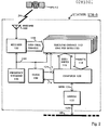
- FIG. 2 a block diagram is shown of one of the stations STN-n of the set STN 30, 32, 34, 36, ... 54 at which the signals from the plurality of GPS satellites are received and reconstructed carrier phase measurements are made.
- each station STN-n receives concurrently the signals transmitted by each of the GPS satellites GPS-12, GPS-14, GPS-16 and GPS-18, such as signals 24 received from satellite GPS-12.
- data communication link 60 illustratively a commercial switched telephone network
- station STN-n communicates with data processor 62, shown in Fig. 1.
- Station STN-n includes upward looking omnidirectional antenna 100, receiver 102, frequency standard 106, clock 108, a plurality of identical tracking channels 112, computer 120, and modem 122.
- Antenna 100 whose phase center is accurately known and positioned with respect to a local geodetic monument, not shown, receives simultaneously the signals transmitted by all satellites in view.
- Antenna 100 is designed to respond to the signals received directly from the satellites through free space, and to reject signals scattered or reflected from nearby objects or surfaces such as the ground below. Rejection of such scattered or reflected signals is important to prevent them from altering the phases of the received signals which ideally are just the directly received signals.
- antenna 100 preferably receives signals from the sky and not from the ground, it is called “upward looking”. Because antenna 100 receives signals from all directions in the sky, it is also called “omnidirectional”.
- a type of antenna well suited for the present application is disclosed in U. S. Patent Number 4,647,942 issued March 3, 1987, entitled “CIRCULARLY POLARIZED ANTENNA FOR SATELLITE POSITIONING SYSTEMS".
- the particular antenna disclosed in Patent 4,647,942 was designed to receive only one of the GPS bands, the L1 band.
- a dual-band, L1 and L2, version of the antenna disclosed in Patent 4,647,942 is available commercially as the antenna of the MACROMETER IITM Interferometric Surveying System.
- MACROMETER II is a trademark of Aero Service Division, Western Geophysical Company of America.
- Antenna 100 is preferably a MACROMETER II antenna or an equivalent.
- the relative-position or "baseline" vectors between the phase centers of the antennas at all of the stations, and also the position vector of the phase center of each antenna with respect to the center of mass of the earth are determined a priori , by known methods, and preferably with better fractional accuracy than is desired for the determinations of the satellite orbits. Errors in the presumed knowledge of these vectors will cause errors in the orbit determinations.
- a composite of the signals simultaneously received from the plurality of satellites by antenna 100 is applied to receiver 102 which converts the signals from the L1 and L2 bands of frequencies at which the signals are received, to low frequencies at which the operations of carrier reconstruction, phase measurement and tracking are more conveniently performed.
- Frequency down-conversion operations are performed within receiver 102 as disclosed in detail hereinbelow with reference to Fig. 3, by heterodyning the received signals with local oscillator signals.
- the oscillator signals are synthesized by coherent multiplication of standard frequency signal 104 provided to receiver 102 by frequency standard 106.
- Carrier reconstruction is also performed within receiver 102. As further disclosed with reference to Fig.
- Bus 110 includes separate data lines for the L1 and the L2 bands.
- Frequency standard 106 is a stable reference standard, such as a commercially available cesium atomic beam resonator controlled oscillator. It has spectral purity sufficient to permit coherent multiplication to L band, and long term stability and accuracy to permit accurate time-keeping.
- Standard frequency signal 104 from frequency standard 106 has a frequency equal to 2 f0, or 10.23 MHz.
- standard frequency signal 104 from frequency standard 106 is applied to and governs the rate of clock 108.
- clock 108 counts cycles of standard frequency signal 104 to generate real time indication 124 which is applied to and governs the operation of computer 120 and all of the tracking channels 112.
- Clock 108 of tracking station STN-n is synchronized with the clocks of the other tracking stations by means of synchronization signal 114 generated by computer 120. (Preferably each station autonomously derives the synchronization signal.)
- synchronization signal 114 may be derived by any of a variety of known methods, including decoding of the GPS signal modulation by known means, not shown, included in receiver 102 and/or in one or more of tracking channels 112.
- the low frequency, digitized, composite of reconstructed carriers output from receiver 102 on bus 110 is applied identically, in parallel, to all of the tracking channels 112 where the phases of the reconstructed carriers are individually measured.
- One tracking channel 112 is assigned to each satellite, and selectively detects only carriers from its assigned satellite, using satellite-specific estimates 116 of the time-varying Doppler shift of the signals received from that satellite.
- Estimates 116 applied to tracking channels 112 by computer 120 are computed by known methods from a priori information about the satellite orbits and the tracking station position which may conveniently be provided to computer 120 from the central processor 62 via data communication link 60.
- An alternative source of information about the satellite orbits is the broadcast information which is carried by the satellite signals and which be read by known methods involving knowledge of the GPS codes.
- the measurements 118 are stored in the memory of computer 120 until it is desired to transfer them to data processor 62 (Fig.®1).
- Data communication link 60 is bidirectional so that information generated by data processor 62 relating to the satellite signals, such as data representing predictions of the frequencies of these signals, may be transferred to computer 120 through modem 122 and may be used by computer 120 to control or to aid the measurement processes.
- estimates 116 applied to tracking channels 112 may be derived partially or wholly from data received by computer 120 from data processor 62 via line 60.
- Computer 120 may also generate the clock synchronization signal 114, which is applied to clock 108 in order to initialize real time indication 124, partially or wholly on the basis of data received from data processor 62 via line 60.
- the information necessary to synchronize clock 108 with the clocks in all other stations and with a standard time such as "GPS" time or Coordinated Universal Time, may be wholly or partially derived from the satellite signals received at one of the stations STN-n.
- Receiver 102 accepts the L1 and L2 band signals simultaneously received from the satellites by antenna 100.
- the composite of spread spectrum signals received in each of these bands is processed in receiver 102 to generate a composite of reconstructed carrier signals.
- These L1- and L2-related, reconstructed composite signals are also sampled in receiver 102, and are applied in digital form via bus 110 to the identical tracking channels 112 where individual satellites' reconstructed carrier phases are measured.
- Reference frequency signal 104 from frequency standard 106 is applied to receiver 102 where it governs the frequency down-conversion and sampling operations which are performed in the course of generating low frequency, digital signals on bus 110.
- Receiver 102 receives the L band signals from antenna 100 via a transmission line 150 which is coupled in turn to a preamplifier assembly 152 including an L1 band pass filter 154, an L2 band pass filter 156, and a low noise preamplification stage 158.
- a transmission line 160 carries the filtered and preamplified signals to a diplex filter 162 which supplies the L1 band signals to L1 sideband separator 168.
- This sideband separator also receives a 1575.42 MHz, L1 band center frequency reference signal 170 generated by a frequency multiplier 172 which is driven by frequency standard 106 through line 104.
- L1 sideband separator 168 generates separate upper and lower side band outputs, 174 and 176 respectively, converted from the upper and lower halves of the L1 band to lower frequencies by heterodyning with L1 band center frequency reference signal 170.
- L1 upper sideband signal 174 and L1 lower sideband signal 176 are filtered by L1 upper sideband filter 178 and L1 lower sideband filter 180 respectively.
- a mixer 186 receives the outputs of these filters and supplies their product to L1 2f0 in-phase sampler 190 and L1 2f0 quadrature sampler 192.
- These samplers are synchronized by frequency standard 106 via line 104 in the case of sampler 190, and via a 90 degree phase shifter 198 in the case of sampler 192.
- the samplers, operating in relative quadrature supply inputs L1I and L1Q to the tracking channels via bus 110.
- the L2 band section of the receiver is similarly organized and includes L2 sideband separator 204, L2 upper sideband filter 210, L2 lower sideband filter 212, mixer 218, L2 2f0 in-phase sampler 222, and L2 2f0 quadrature sampler 224, all as illustrated in Fig. 3.
- the spread-spectrum composite of L1 and L2 band signals simultaneously received from the plurality of satellites is carried from antenna 100 to preamplifier assembly 152 by transmission line 150 which is made as short as possible, preferably less than 1 meter long, in order to minimize losses. Therefore preamplifier assembly 152 should be mounted as close to antenna 100 as practicable with the antenna having a clear view of the sky.
- Preamplifier assembly 152 serves to amplify the received signals sufficiently that these signals can be carried a moderately long distance, e.g. via transmission line 160, from the location of antenna 100 and preamplifier assembly 152, to the location of the remaining portion of receiver 102 which may be relatively remote.
- preamplifier assembly 152 the signals received via transmission line 150 are split and applied to the inputs of L1 band pass filter 154 and L2 band pass filter 156. These are high quality, low loss band pass filters tuned to the L1 and L2 frequency bands, respectively. They are used to prevent any strong out-of-band signals which may be picked up by antenna 100 from reaching the low noise amplifier 158 and possibly burning it out or overloading it or subsequent stages of receiver 102.
- transmission line 160 may also carry d.c. power from a power supply in receiver 102, not shown.
- Diplex filter 162 is a frequency selective signal splitter which separates the L1 band signals from the L2 band signals arriving via transmission line 160, and outputs L1 band signals 165 and L2 band signals 166 separately as shown.
- the L1 band signals 164 are applied to the input of L1 sideband separator 168 and the L2 band signals 166 are applied to the input of L2 sideband separator 204.
- L1 sideband separator 168 may be configured conveniently as described in detail in an article in the Proceedings of the IEEE, vol. 59 (1971), pp. 1617-1618, by Alan E. E. Rogers, and further described in United Kingdom Patent No. 2,120,489, published Feb. 26,1986 and entitled "Method and system for determining position using signals from satellites".
- L1 upper sideband signal 174 output from L1 sideband separator 168 is a spread spectrum composite representing that portion of L1 band signals 164 having frequencies higher than 1575.42 MHz, the frequency of L1 center frequency reference signal 170.
- the phase and the frequency of L1 center frequency reference signal 170 are subtracted from the phases and the frequencies of the Fourier components of the higher-frequency half of the spectrum of L1 band signals 164 to obtain the phases and the frequencies of the corresponding Fourier components of L1 upper sideband signal 174.
- L1 lower sideband signal 176 output from L1 sideband separator 168 is a spread spectrum composite representing that portion of L1 band signals 164 having frequencies lower than 1575.42 MHz, the frequency of L1 center frequency reference signal 170.
- the phases and the frequencies of the Fourier components of the lower-frequency half of the spectrum of L1 band signals 164 are subtracted from the phase and the frequency of L1 center frequency reference signal 170 to obtain the phases and the frequencies of the corresponding Fourier components of L1 lower sideband signal 176.
- L1 upper and lower sideband signals 174 and 176 are applied to upper and lower sideband filters 178 and 180, respectively. These two filters preferably have identical properties. They are used to reject noise and any interfering signals outside the useful range of frequencies in the upper and lower sideband signals 174, 176. This range extends from about 10 kHz to about 9 MHz, except for a narrow band of frequencies centered at f0, or 5.115 MHz. These filters should also provide rejection at a frequency of 2f0, or 10.23 MHz.
- each filter passband is preferably matched to the shape of one sideband of the P-code related component of a GPS signal.
- the filter has a half-power bandwidth of about 4.5 MHz.
- the rejection of frequencies below about 10 kHz prevents any L1 band signals received at frequencies less than 10 kHz above or below the L1 band center frequency from reaching mixer 186, where the second harmonics of the 308 f0, L1 band center frequency carrier waves are constructed.
- These carriers, as received may have frequencies differing from 308 f0 by up to about 5 kHz in either direction, by virtue of Doppler shift.
- Their second harmonics are Doppler-shifted by plus or minus up to 10 kHz.
- the low-frequency cutoffs of filters 178 and 180 prevent interference with the reconstructed L1 band center frequency carriers.
- the notch centered at f0 in filters 178 and 180 prevents L1 band signals received at frequencies near 307 f0 and 309 f0 from interfering with the L1 band, f0 subcarriers.
- the second harmonics of these carriers are also reconstructed in mixer 186.
- the frequencies of these reconstructed second harmonics as they appear in L1 product 188 are near 2 f0, and differ from 2f0 by up to about 30 Hz in either direction, due to Doppler shift.
- the range of frequencies of these signals is relatively narrow, and the notches of filters 178 and 180 could be made equally narrow. However, it is more convenient to provide much wider notches, of the order of 10 kHz or even 100 kHz centered on 2f0. Even with the larger notch width, a relatively small fraction of the desired signal power is lost since this power is spread over a bandwidth of several MHz.
- filters 178 and 180 should have phase shifts which are within a few degrees of a linear function of frequency. In other words, the filters should be nondispersive. This property is required for the phase-coherent combination of spectral components from throughout the useful frequency range, in the carrier reconstruction in mixer 186.
- Filters 178 and 180 having all the properties specified herein may be configured using known techniques, for example by cascading 10 kHz high-pass and 5.115 MHz notch filters with a phase-linear low-pass filter approximately matched to the P-code modulation bandwidth.
- L1 product 188 which is generated by mixer 186 is applied to L1 2f0 in-phase sampler 190 and L1 2f0 quadrature sampler 192 as shown.
- L1 2f0 in-phase sampler 190 samples L1 product 188 at a uniform rate of 2f0, or 10.23 MHz, in accordance with standard frequency signal 104 received from frequency standard 106.
- L1 2f0 quadrature sampler 192 also samples L1 product 188 at a uniform rate of 2f0, or 10.23 MHz, in accordance with standard frequency signal 104 received from frequency standard 106.
- phase of the sampling by L1 2f0 quadrature sampler 192 lags that of L1 2f0 in-phase sampler 190 because L1 2f0 quadrature sampler 192 is driven by quadrature sampling frequency signal 148, generated by a 90° phase shifter 198 which delays standard frequency signal 104 by one-quarter cycle of phase.
- L1 2f0 in-phase sampler 190 generates L1 in-phase sampled product 194 which is a digital signal, preferably including only one bit per sample, to indicate just the sign.
- L1 2f0 quadrature sampler 192 generates L1 quadrature sampled product 196 which is of the same form. Limiting these sampled products to one bit simplifies the subsequent digital signal processing circuitry, while degrading the signal to noise ratios tolerably.
- L1 in-phase sampled product 194 provides the "L1I” input to each tracking channel 112, and L1 quadrature sampled product 196 provides the "L1Q" input to each tracking channel 112, as shown in Figs. 3 and 4.
- the L1 in-phase and quadrature sampled products 194 and 196 respectively, are carried, together with similar signals from the L2 band section of receiver 102, via bus 110 to the tracking channel 112.
- the digital sampling rate greatly exceeds the frequencies of the reconstructed L1 center frequency carriers, all less than 10 kHz, in L1 product 188. Thus, the frequencies and phases of these reconstructed carriers are preserved in the sampling process.
- the sampling rate of 2f0 is nominally exactly equal to the second harmonic of the f0 carrier implicit in the signals transmitted by each satellite. As received, and after the frequency-doubling which occurs in the carrier reconstruction process, these carriers have frequencies differing from the 2f0 sampling rate by amounts between minus and plus about 30 Hz.
- L1 2f0 in-phase sampler 190 and L1 2f0 quadrature sampler 192 act as mixers, subtracting the 2f0 sampling frequency from the reconstructed carrier frequencies near 2f0 to yield reconstructed carrier frequencies in L1 in-phase sampled product 194 and L1 quadrature sampled product 196 in the range from minus to plus 30 Hz. Note that negative frequencies are distinct from positive frequencies in these sampled products because the two samplers operate in phase quadrature.
- the signal to noise ratio of the reconstructed f0 carriers is degraded by noise appearing in L1 product 188 at frequencies in the zero to 30 Hz range.
- performance of the system can be improved if desired, by providing a separate pair of quadrature samplers like L1 2f0 in-phase sampler 190 and L1 2f0 quadrature sampler 192, but connected to mixer 186 by a band-pass filter tuned to the desired frequency band, centered at 2f0 in this case.
- L1I and L1Q signals applied to 616 f0 detector 302 in tracking channel 112, disclosed below with reference to Fig. 4, would continue to be derived from L1 2f0 in-phase sampler 190 and L1 2f0 quadrature sampler 192, as shown.
- the added pair of samplers would drive L1 2f0 detector 304 (described hereinafter with reference to Fig. 4) in tracking channel 112. Similar additions and changes could be made for the L2 section of receiver 102 and tracking channel 112.
- L2 section of receiver 102 is organized like the L1 section.
- L2 band signals 166 output by diplex filter 162 are applied to L2 sideband separator 204 which heterodynes these signals with L2 center frequency reference signal 202.
- L2 center frequency reference signal 202 has a frequency of 240 f0, equal to 1227.60 MHz, and is derived from 2f0 standard frequency signal 104 by frequency multiplication in ⁇ 120 frequency multiplier 200. Except for the difference in inputs, L2 sideband separator 204 operates exactly like, and may be constructed exactly as, L1 sideband separator 168.
- L2 sideband separator 204 generates separate L2 upper sideband signal 206 and L2 lower sideband signal 208 outputs at baseband, representing the upper and lower frequency halves of the spectrum of the L2 band, just as disclosed above with reference to L1 sideband separator 168.
- the L2 upper and lower sideband signals 206, 208 are applied to L2 upper and lower sideband filters 210, 212, respectively. Except for the difference in inputs, these filters operate exactly like, and may be constructed exactly as, L1 upper sideband filter 178 and L1 lower sideband filter 180.
- Filtered L2 upper and lower sidebands signal 214 and 216, output from the filters 210 and 212, respectively, are applied to mixer 218 which operates like mixer 186 in the L1 section of receiver 102.
- L2 product 220 output from mixer 218 is applied to L2 2f0 in-phase sampler 222 and L2 2f0 quadrature sampler 224 which, again, are exactly like their counterparts in the L1 section: that is, L1 2f0 in-phase sampler 190 and L1 2f0 quadrature sampler 192.
- L2 in-phase sampler 222 samples L2 product 220 in response to standard frequency signal 104
- L2 quadrature sampler 224 samples L2 product 220 in response to quadrature sampling frequency signal 148 which is derived, as mentioned above, by delaying the phase of standard frequency signal 104 in 90° phase shifter 198.
- the output of the in-phase sampler 222 is L2 in-phase sampled product 226, also labeled "L2I” in Figs. 3 and 4.
- the output of quadrature sampler 224 is L2 quadrature sampled product 228, also labeled "L2Q” in Figs. 3 and 4.
- a plurality of reconstructed carrier components is found, including both a reconstructed second harmonic of the center frequency carrier and a reconstructed second harmonic of the f0 subcarrier implicit in the L2 band signals from each visible satellite.
- the reconstructed carriers are distinguished by their different Doppler shifts.
- the Doppler shift of each carrier is proportional to its frequency as transmitted, and to the rate of change of the satellite-to-receiver range (sometimes called the "range rate", or the "line-of-sight velocity").
- tracking channel 112 includes a range generator 300 which receives a satellite-specific range rate estimate 298, included in estimates 116 from computer 120, and generates therefrom a 2f0 phase estimate 310 which is used by four synchronous detectors to detect and measure the phases of four reconstructed carriers of the particular satellite to which this tracking channel 112 is assigned.
- These carriers are the L1 band center frequency carrier, the L2 band center frequency carrier, the f0 subcarrier implicit in the L1 band signals, and the f0 subcarrier implicit in the L2 band signals.
- L1 in-phase sampled product 194 and L1 quadrature sampled product 196 from receiver 102, received by tracking channel 112 via bus 110, are applied to 616 f0 detector 302 which detects the second harmonic of the 308 f0, L1 band center frequency carrier.
- the product signals 194, 196 are also applied to L1 2f0 detector 304 which detects the second harmonic of the f0, L1 band subcarrier.
- L2 in-phase sampled product 226 and L2 quadrature sampled product 228 from receiver 102 are applied to 480 f0 detector 306 which detects the second harmonic of the 240 f0, L2 band center frequency carrier, and also to L2 2f0 detector 308 which detects the second harmonic of the f0, L2 band subcarrier.
- Each of the four synchronous detectors in tracking channel 112 also receives an estimate of the time-varying phase of the particular carrier which it is supposed to detect, and each produces a measurement of the difference between the actual carrier phase and the estimate of this phase.
- All four carrier phase estimates, one for each carrier to be detected, are derived by multiplying 2f0 phase estimate 310, generated by range generator 300 from range rate estimate 298, by appropriate factors. This is appropriate since all four carriers were generated from the same fundamental frequency source within the same satellite, and since all have equal fractional frequency shifts due to the Doppler effect.
- the 2f0 phase estimate 310 is applied directly, that is without multiplication, to L1 2f0 detector 304 and L2 2f0 detector 308.
- the same 2f0 phase estimate 310 is multiplied by a factor of 308 in ⁇ 308 multiplier 312 whose output, estimate 314, is applied to 616 f0 detector 302.
- the same 2f0 phase estimate 310 is multiplied by a factor of 240 in ⁇ 240 multiplier 316 whose output, estimate 318, is applied to 480 f0 detector 306.
- the 616 f0 detector 302 produces 616 f0 residual phase measurement 320, a measurement of the difference between the actual phase of the reconstructed, second harmonic, L1 center frequency carrier of the selected satellite and the 616 f0 phase estimate 314.
- L1 2f0 detector 304 produces L1 2f0 residual phase measurement 322, a measurement of the difference between the actual phase of a reconstructed, sound harmonic, L1b and f0 subcarrier of the selected satellite and the 2f0 phase estimate 310.
- the 480 f0 detector 306 produces 480 f0 residual phase measurement 324, a measurement of the difference between the actual phase of the reconstructed, second harmonic, L2 center frequency carrier of the selected satellite and the 480 f0 phase estimate 318.
- L2 2f0 detector 308 produces L2 2f0 residual phase measurement 326, a measurement of the difference between the actual phase of the reconstructed, second harmonic, L2 band f0 subcarrier of the selected satellite and the 2f0 phase estimate 310.
- Each of the four sunchronous detectors also produces a measurement of the power of the related carrier.
- 616 f0 detector 302 produces L1 center frequency carrier power measurement 330
- L1 2f0 detector 304 produces L1 subcarrier power measurement 332
- 480 f0 detector 306 produces L2 center frequency carrier power measurement 334
- L2 2f0 detector 308 produces L2 subcarrier power measurement 336.
- Each synchronous detector such as 616 f0 detector 302 which detects the reconstructed, second harmonic, L1 center frequency carrier of the selected satellite, selectively detects the signal received from the selected satellite and rejects signals from other satellites because, virtually always, the desired satellite's reconstructed carrier signal differs in frequency from the undesired satellites'.
- Each synchronous detector responds only to input signal frequencies which are very near to the frequency, that is the rate, of the related carrier phase estimate, such as 616 f0 phase estimate 314 which is supplied to 616 f0 detector 302.
- the phase estimate supplied to each synchronous detector is applied within the detector to the input signals, such as L1I and L1Q, in order to subtract the phase estimate from the phases of the input signals.
- the input signals include a plurality of reconstructed carrier components, from all visible satellites.
- One of these input signal components, the desired component has phase varying with time at very nearly the same rate as the phase estimate.
- the phase of the desired component is therefore virtually static, so this signal component may be distinguished from noise and other signals by integrating the composite signal for an interval of time.
- Such an integration is performed within each synchronous detector, such as the 616 f0 detector 302, as disclosed further below with reference to Fig. 5.
- range generator 300 In order for this method of signal selection to work, of course, the rate of the phase estimate applied to the synchronous detector must match the phase rate, or frequency, of the desired signal component sufficiently accurately. Because range rate estimate 298 from computer 120 might not be sufficiently accurate, range generator 300 also receives an input from 616 f0 residual phase measurement 320 which serves as an error signal and is applied in range generator 300 to correct 2f0 phase estimate 310. Thus a closed feedback loop is formed which includes the range generator 300, the ⁇ 308 multiplier 312, and the 616 f0 detector 302. This loop acts as a phase-locked tracking loop to track the phase of the L1 center frequency carrier of the signals received from the selected satellite.
- the four carrier power measurements are included in measurements 118 along with 2f0 phase estimate 310 and the four residual phase measurements: 616 f0 residual phase measurement 320, L1 2f0 residual phase measurement 322, 480 f0 residual phase measurement 324, and L2 2f0 residual phase measurement 326.
- the latter measurements are called "residual" phase measurements because each represents only the residual, or difference, between the related actual and estimated carrier phase. Addition of each residual phase measurement value to the related phase estimate yields the total value of the "one-way phase" measurement for the related carrier.
- Such additions are conveniently performed in computer 120, although they might also be performed in central data processor 62.
- the 616 f0 detector 302 is shown in detail in Fig. 5. It is convenient to construct all four detectors identically although the preferred value of signal integration time is not the same for all four. As discussed hereinbelow, the preferred integration time for 616 f0 detector 302 is 1 second, whereas the preferred integration time for detectors 304, 306 and 308 is 100 seconds.
- detector 302 While the construction and operation of the other detectors may be understood from the description of detector 302, a subtle difference should be noted between the operations of the two center frequency carrier detectors (616 f0 detector 302 and 480 f0 detector 306) on one hand, and the two subcarrier detectors (L1 2f0 detector 304 and L2 2f0 detector 308) on the other. This difference arises not from any differences between the detectors themselves, but from a difference between the center frequency carriers and the subcarriers as they appear in the I and Q inputs.
- the reconstructed center frequency carriers appear with frequencies in the range from zero to about 10 kHz in L1 product 188.
- the frequency of a reconstructed center frequency carrier in L1 product 188 is equal to twice the magnitude (i.e., twice the absolute value) of the Doppler shift of the related, 308 f0, L1 band center frequency carrier.
- Positive and negative Doppler shifts of equal magnitude yield the same frequency in L1 product 188.
- a consequence of this Doppler "imaging” is a 3 dB loss of signal to noise ratio (SNR).
- SNR signal to noise ratio
- a less important consequence is the possibility of interference between two satellites having equal magnitude, opposite Doppler shifts. Such interference occurs in practice but so rarely, and so briefly, that it can be ignored.
- the imaging and the consequent SNR loss could be eliminated by the addition of a quadrature counterpart of mixer 186 in receiver 102. Actual experience has shown such an addition to be unnecessary, so it is omitted from the preferred system disclosed herein.
- the reconstructed f0 subcarriers unlike the reconstructed center frequency carriers, do not suffer from Doppler imaging in the "I" and "Q" signals from receiver 102.
- Each reconstructed subcarrier signal appears in Q with phase differing by 90° from its phase in I. The sense of this phase difference, leading or lagging, depends on whether the Doppler shift is positive or negative.
- I and Q provide a rotating "phasor" description of a reconstructed subcarrier signal.
- the phasor concept is helpful to understanding the operations of all the synchronous detectors, and will be used in the following description of the operation of the 616 f0 detector 302 despite the fact that the phasor representing the reconstructed L1 center frequency carrier signal does not properly rotate about the origin of the I-Q plane; rather, it oscillates on a line of unit slope. It will be recalled that such a linearly oscillating phasor is the sum of two rotating phasors of equal magnitude, with equal rotation rates, rotating in opposite directions.
- the 616 f0 detector 302 responds to one of these phasors and rejects the other, just as it rejects phasors of other satellites. In the following description of detector operation the rejected phasor will be ignored. Thus, the same description can be taken to apply to all four detectors.
- the 616 f0 detector 302 receives as inputs from receiver 102, L1 in-phase sampled product 194, "L1I”, and L1 quadrature sampled product 196, "L1Q”.
- L1I and L1Q were generated in the receiver 102 by sampling L1 product 188 from mixer 186 as shown in Fig. 3.
- Present in both L1I and L1Q is a composite of reconstructed carrier signals, simultaneously including signals from all visible satellites.
- the reconstructed center frequency carrier of the L1 band signal received from the particular satellite to which tracking channel 112 has been assigned is selected by the 616 f0 detector 302.
- the selection is based on an estimate of the time-varying phase of this specific carrier encoded in 616 f0 phase estimate 314 which is generated by ⁇ 308 multiplier 312.
- Both 2f0 phase estimate 310 and 616 f0 phase estimate 314 are binary digital signals, and ⁇ 308 multiplier 312 is a digital multiplier.
- the 2f0 phase estimate 310 which is generated by range generator 300 is updated at a fixed rate of 2f0/93, or exactly 110 KHz, in accordance with 2f0 standard frequency signal 104 from frequency standard 106 and real time indication 124 from clock 108 (Figs. 2, 3).
- the ⁇ 308 multiplier 312 operates to update 616 f0 phase estimate 314 at the same rate.
- the 616 f0 phase estimate 314 is applied to the I and Q signals, (L1 in-phase sampled product 194 and L1 quadrature sampled product 196), in quadrant rotation logic 400. From these three digital input signals, quadrant rotation logic 400 generates another pair of digital "I” and "Q” signals, in-phase rotated signal 402 and quadrature rotated signal 404.
- each of L1 in-phase sampled product 194 and L1 quadrature sampled product 196 is a one-bit digital signal.
- the two bits taken together indicate the quadrant of the phasor representing the composite of all the reconstructed L1 carriers.
- each of in-phase rotated signal 402 and quadrature rotated signal 404 is a one-bit digital signal. These two bits taken together also indicate the quadrant of a phasor representing the composite of all the reconstructed L1 carriers.
- the latter phasor is rotated with respect to the former phasor, through the action of quadrant rotation logic 400, by an angle equal (modulo 360 degrees) to 616 f0 phase estimate 314.
- 616 f0 estimate 314 represents phase in the form of a binary number.
- the unit of this representation is one cycle of phase.
- the first two bits to the right of the binary point therefore indicate the quadrant of 616 f0 estimate 314.
- These two bits of 616 f0 phase estimate 314 are combined with the two bits of L1 in-phase sampled product 194 and L1 quadrature sampled product 196 in quadrant rotation logic 400 to generate the two output bits, in-phase rotated signal 402 and quadrature rotated signal 404.
- This logic must operate at a clock rate of 2f0, the rate of the one-bit I & Q signal inputs.
- the truth table of this logic may readily be completed from the foregoing description, and is given in the U. S.
- In-phase rotated signal 402 is integrated for an interval of time to distinguish the selected signal component from the noise and other components present in the composite, by means of clocked counter 410.
- quadrature rotated signal 404 is integrated by means of clocked counter 420.
- the two counters are identical in construction and operation. The integrations by these counters are started and stopped by real time indication 124 from clock 108. As mentioned above, the integration time interval is 1 second in the case of 616 f0 detector 302, and 100 seconds for the other three detectors in tracking channel 112. In 616 f0 detector 302, an integration begins every second on the second. At these times clocked counter 410 and clocked counter 420 are reset to zero and commence counting.
- Each counter is clocked by standard frequency signal 104 from frequency standard 106. On every cycle of this 2f0 clock signal, each counter is incremented if and only if its input, in-phase rotated signal 402 for clocked counter 410 and quadrature rotated signal 404 for clocked counter 420, is TRUE. At the end of the integration time interval, the accumulated count in clocked counter 410 is read out as inphase accumulation 412, and the accumulated count in clocked counter 420 is read out as quadrature accumulation 422.
- range generator 300 receives satellite-specific range rate estimate 298 from computer 120 and generates 2f0 phase estimate 310 which is applied directly or indirectly to all four synchronous detectors in tracking channel 112.
- the 2f0 phase estimate 310 is applied directly to detectors 304 and 308, to detector 302 via ⁇ 308 multiplier 312, and to detector 306 via the ⁇ 240 multiplier 316.
- the relevant phase estimate is used to rotate the input composite-signal phasor at just the right rate to counter, and stop, the rotation of the particular phasor component representing the carrier component which is to be detected.
- range generator 300 includes two digital registers, range register 450 and rate register 460.
- Range register 450 contains a binary number representing a biased estimate of range between the antenna 100 of tracking station STN-n, and the particular satellite, such as GPS-12, to which this tracking channel 112 is assigned. The range is represented in units equal to one wavelength at a frequency of 2f0, approximately 29 meters.
- Range register 450 is a 58-bit binary register with 20 bits to the left and 38 bits to the right of the binary point. The number contained in range register 450 is 2f0 phase estimate 310. As disclosed above with reference to Figs.
- 2f0 phase estimate 310 is updated at a uniform rate 110,000 times per second.
- the number (2f0 phase estimate 310) in range register 450 is replaced with the sum, computed in adder 470, of 2f0 phase estimate 310 plus range increment 462 which is contained in rate register 460.
- a new value of 616 f0 residual phase measurement 320 is received from 616 f0 detector 302, is rescaled in scale converter 464, and the result is added into the sum formed by adder 470.
- Range increment 462 represents the time rate of change of 2f0 phase estimate 310 in units equal to 110,000 kHz, that is, 110,000 cycles of phase per second. Like range register 450, rate register 460 and adders 468 and 470 require 38 bits to the right of the binary point. However, rate register 460 and adder 468 need have no bits to the left of the binary point.
- the feedback process is also effected by adding 616 f0 residual phase measurement 320, after scaling by scale converter 466, into rate register 460 by means of adder 468.
- the value (i.e., range increment 462) in rate register 460 is replaced by the sum, formed in adder 468, of the current value in rate register 460 and the value of range rate estimate 298 received from computer 120.
- the scaled value of 616 f0 residual phase measurement 320 is also added into this sum. Since phase tracking errors, represented by 616 f0 residual phase measurement 320, are accumulated in rate register 460 whose contents are further accumulated in range register 450, the feedback loop is a second-order loop.
- the loop dynamics are determined by the scale factors applied to 616 f0 residual phase measurement 320 in scale converter 464 and scale converter 466.
- the optimal value of loop bandwidth given the stability of the frequency standards of the existing GPS satellites, is equal to about 0.5 Hz.
- the scale factor applied in scale converter 466 may be set in accordance with known techniques of feedback control.
- the phase locked loop is rate-aided by computer 120 which furnishes an updated range rate estimate 298 ten times per second to adder 468.
- Range rate estimate 298 represents the amount by which range increment 462 is expected to change each 0.1 second.
- range rate estimate 298 represents a prediction of the acceleration of 2f0 phase estimate 310.
- a path 458 bypassing adder 468 is provided in order to load an initial range increment 462 into rate register 460.
Applications Claiming Priority (2)
| Application Number | Priority Date | Filing Date | Title |
|---|---|---|---|
| US2871287A | 1987-03-20 | 1987-03-20 | |
| US28712 | 1987-03-20 |
Publications (2)
| Publication Number | Publication Date |
|---|---|
| EP0283302A2 true EP0283302A2 (de) | 1988-09-21 |
| EP0283302A3 EP0283302A3 (de) | 1990-05-02 |
Family
ID=21845004
Family Applications (1)
| Application Number | Title | Priority Date | Filing Date |
|---|---|---|---|
| EP88302388A Withdrawn EP0283302A3 (de) | 1987-03-20 | 1988-03-18 | Verfahren zum Feststellen von Bahndaten |
Country Status (5)
| Country | Link |
|---|---|
| EP (1) | EP0283302A3 (de) |
| JP (1) | JPS63314482A (de) |
| AU (1) | AU602198B2 (de) |
| CA (1) | CA1309478C (de) |
| NO (1) | NO172518C (de) |
Cited By (12)
| Publication number | Priority date | Publication date | Assignee | Title |
|---|---|---|---|---|
| EP0406021A2 (de) * | 1989-06-30 | 1991-01-02 | Sharp Kabushiki Kaisha | Platten-Aufzeichnungs-/-Wiedergabegerät |
| FR2706230A1 (fr) * | 1993-06-07 | 1994-12-16 | Alcatel Mobile Comm France | Sélection d'un satellite de rattachement. |
| US6771214B2 (en) | 2001-09-12 | 2004-08-03 | Data Fusion Corporation | GPS near-far resistant receiver |
| EP2019971A2 (de) * | 2006-04-28 | 2009-02-04 | Loctronix Corporation | System und verfahren zur positionierung in konfigurierten umgebungen |
| US7626542B2 (en) | 2005-02-25 | 2009-12-01 | Data Fusion Corporation | Mitigating interference in a signal |
| EA019666B1 (ru) * | 2010-12-20 | 2014-05-30 | Федеральное Государственное Автономное Образовательное Учреждение Высшего Профессионального Образования "Сибирский Федеральный Университет" (Сфу) | Способ угловой ориентации объекта по сигналам спутниковых радионавигационных систем |
| EP3207401A4 (de) * | 2014-10-16 | 2018-06-20 | Henry H. Liao | Vorrichtung zur ortung und positionierung unter verwendung von fm-rundfunksignalen und eines phasendifferenzberechnungsverfahrens |
| CN108562295A (zh) * | 2018-07-23 | 2018-09-21 | 电子科技大学 | 一种基于同步卫星二体模型的三站时差定轨方法 |
| CN111232247A (zh) * | 2020-01-17 | 2020-06-05 | 上海埃依斯航天科技有限公司 | 一种高可靠性的微纳卫星测控系统 |
| CN113029161A (zh) * | 2021-03-10 | 2021-06-25 | 中国科学院上海天文台 | 基于互相关谱合成的空间vlbi信号增强方法及系统 |
| CN113393000A (zh) * | 2021-05-07 | 2021-09-14 | 杭州数知梦科技有限公司 | 通过移动预约提升常规公交线路客流量的方法 |
| CN113581501A (zh) * | 2021-08-27 | 2021-11-02 | 重庆两江卫星移动通信有限公司 | 一种适用于组网低轨卫星联合定轨的系统及方法 |
Families Citing this family (1)
| Publication number | Priority date | Publication date | Assignee | Title |
|---|---|---|---|---|
| JP4937613B2 (ja) * | 2006-03-22 | 2012-05-23 | 国立大学法人 鹿児島大学 | 軌道決定装置、軌道決定方法、及びコンピュータプログラム |
Family Cites Families (3)
| Publication number | Priority date | Publication date | Assignee | Title |
|---|---|---|---|---|
| US4667203A (en) * | 1982-03-01 | 1987-05-19 | Aero Service Div, Western Geophysical | Method and system for determining position using signals from satellites |
| US4894662A (en) * | 1982-03-01 | 1990-01-16 | Western Atlas International, Inc. | Method and system for determining position on a moving platform, such as a ship, using signals from GPS satellites |
| US4734702A (en) * | 1986-02-25 | 1988-03-29 | Litton Systems, Inc. | Passive ranging method and apparatus |
-
1988
- 1988-03-11 NO NO881084A patent/NO172518C/no unknown
- 1988-03-16 CA CA000561648A patent/CA1309478C/en not_active Expired - Fee Related
- 1988-03-17 AU AU13210/88A patent/AU602198B2/en not_active Ceased
- 1988-03-18 EP EP88302388A patent/EP0283302A3/de not_active Withdrawn
- 1988-03-18 JP JP63063752A patent/JPS63314482A/ja active Pending
Non-Patent Citations (5)
| Title |
|---|
| ELECTRONICS AND COMMUNICATION IN JAPAN, vol. 55-B, no. 5, 1972, pages 102-108, New York, US; M. FUJITA et al.: "Baseline arrangement of radio interferometer array for tracking artificial satellites" * |
| IEEE EASCON 1985, Washington, DC, 28th-30th October 1985, pages 9-18, IEEE, New York, US; P.Y.C. HWANG et al.: "GBS Geodesy: Experimental results using the KALMAN filter approach" * |
| IEEE PLANS'86, Las Vegas, 4th-7th November 1986, pages 243-250, IEEE, New York, US; G. BEUTLER et al.: "Using the Global Positioning System (GPS) for High Precision Geodetic Surveys: Highlights and problem areas" * |
| JOURNAL OF THE BRITISH INSTITUTION OF RADIO ENGINEERS, vol. 22, no. 2, August 1961, pages 97-107, London, GB; B.G. PRESSEY: "Radio Tracking of Artificial Earth Satellites" * |
| MANUSCRIPTA GEODAETICA, vol. 11, no. 4, 1986, pages 282-288, Springer-Verlag, DE; Y. BOCK et al.: "Interferometric analysis of GPS phase observations" * |
Cited By (19)
| Publication number | Priority date | Publication date | Assignee | Title |
|---|---|---|---|---|
| EP0406021A2 (de) * | 1989-06-30 | 1991-01-02 | Sharp Kabushiki Kaisha | Platten-Aufzeichnungs-/-Wiedergabegerät |
| EP0406021A3 (en) * | 1989-06-30 | 1993-09-29 | Sharp Kabushiki Kaisha | Disk recording and reproducing device |
| FR2706230A1 (fr) * | 1993-06-07 | 1994-12-16 | Alcatel Mobile Comm France | Sélection d'un satellite de rattachement. |
| WO1994029969A1 (fr) * | 1993-06-07 | 1994-12-22 | Alcatel Mobile Communication France | Selection d'un satellite de rattachement |
| US6771214B2 (en) | 2001-09-12 | 2004-08-03 | Data Fusion Corporation | GPS near-far resistant receiver |
| US7626542B2 (en) | 2005-02-25 | 2009-12-01 | Data Fusion Corporation | Mitigating interference in a signal |
| EP2019971A2 (de) * | 2006-04-28 | 2009-02-04 | Loctronix Corporation | System und verfahren zur positionierung in konfigurierten umgebungen |
| EA019666B1 (ru) * | 2010-12-20 | 2014-05-30 | Федеральное Государственное Автономное Образовательное Учреждение Высшего Профессионального Образования "Сибирский Федеральный Университет" (Сфу) | Способ угловой ориентации объекта по сигналам спутниковых радионавигационных систем |
| EP3207401A4 (de) * | 2014-10-16 | 2018-06-20 | Henry H. Liao | Vorrichtung zur ortung und positionierung unter verwendung von fm-rundfunksignalen und eines phasendifferenzberechnungsverfahrens |
| CN108562295A (zh) * | 2018-07-23 | 2018-09-21 | 电子科技大学 | 一种基于同步卫星二体模型的三站时差定轨方法 |
| CN108562295B (zh) * | 2018-07-23 | 2021-07-02 | 电子科技大学 | 一种基于同步卫星二体模型的三站时差定轨方法 |
| CN111232247A (zh) * | 2020-01-17 | 2020-06-05 | 上海埃依斯航天科技有限公司 | 一种高可靠性的微纳卫星测控系统 |
| CN111232247B (zh) * | 2020-01-17 | 2023-02-07 | 上海埃依斯航天科技有限公司 | 一种高可靠性的微纳卫星测控系统 |
| CN113029161A (zh) * | 2021-03-10 | 2021-06-25 | 中国科学院上海天文台 | 基于互相关谱合成的空间vlbi信号增强方法及系统 |
| CN113029161B (zh) * | 2021-03-10 | 2024-04-19 | 中国科学院上海天文台 | 基于互相关谱合成的空间vlbi信号增强方法及系统 |
| CN113393000A (zh) * | 2021-05-07 | 2021-09-14 | 杭州数知梦科技有限公司 | 通过移动预约提升常规公交线路客流量的方法 |
| CN113393000B (zh) * | 2021-05-07 | 2022-11-11 | 杭州数知梦科技有限公司 | 通过移动预约提升常规公交线路客流量的方法 |
| CN113581501A (zh) * | 2021-08-27 | 2021-11-02 | 重庆两江卫星移动通信有限公司 | 一种适用于组网低轨卫星联合定轨的系统及方法 |
| CN113581501B (zh) * | 2021-08-27 | 2023-02-28 | 重庆两江卫星移动通信有限公司 | 一种适用于组网低轨卫星联合定轨的系统及方法 |
Also Published As
| Publication number | Publication date |
|---|---|
| NO881084L (no) | 1988-09-21 |
| NO881084D0 (no) | 1988-03-11 |
| JPS63314482A (ja) | 1988-12-22 |
| AU1321088A (en) | 1988-09-22 |
| NO172518C (no) | 1993-07-28 |
| EP0283302A3 (de) | 1990-05-02 |
| CA1309478C (en) | 1992-10-27 |
| AU602198B2 (en) | 1990-10-04 |
| NO172518B (no) | 1993-04-19 |
Similar Documents
| Publication | Publication Date | Title |
|---|---|---|
| US4912475A (en) | Techniques for determining orbital data | |
| US4870422A (en) | Method and system for determining position from signals from satellites | |
| US4667203A (en) | Method and system for determining position using signals from satellites | |
| US5384574A (en) | System for determining position from suppressed carrier radio waves | |
| US5619212A (en) | System for determining position from suppressed carrier radio waves | |
| US4797677A (en) | Method and apparatus for deriving pseudo range from earth-orbiting satellites | |
| US4809005A (en) | Multi-antenna gas receiver for seismic survey vessels | |
| AU629728B2 (en) | Method and system for determining data using signals from gps satellites | |
| US5347285A (en) | Method and apparatus for tracking the position and velocity of airborne instrumentation | |
| EP0198029B1 (de) | Verbessertes erdumfassendes ortungssystem mit entfernungsänderungsverfahren | |
| AU637747B2 (en) | P-code-aided global positioning system receiver | |
| US4860018A (en) | Continuous wave interference rejection for reconstructed carrier receivers | |
| AU602198B2 (en) | Techniques for determining orbital data | |
| US5036330A (en) | Ranging system using correlation between two spread spectrum wave signals | |
| RU2115137C1 (ru) | Дальномерный способ определения местоположения и составляющих вектора скорости объектов по радиосигналам космических аппаратов спутниковых радионавигационных систем | |
| WO1984001832A1 (en) | Method and apparatus for deriving pseudo range from earth-orbiting satellites | |
| EP0664008B1 (de) | Verfahren und gerät zur verfolgung der position und geschwindigkeit von sich im flug befindlichen instrumenten | |
| RU2624634C1 (ru) | Способ определения скорости распространения и направления прихода ионосферного возмущения | |
| Hui | On satellite signal processing techniques applicable to GPS geodetic equipment | |
| FI85916C (fi) | Foerfarande foer att avleda lokaliseringsrelaterad data fraon signaler med spridningsspektrum. | |
| Dubose et al. | VHF navigation experiment | |
| Ramasastry et al. | Very Long Baseline Interferometer/VLBI/experiments using ATS-3 and ATS-5 satellites | |
| Greenspan et al. | Accurate Baseline Determination by Radio Interferometry on NAVSTAR GPS Satellite Transmission | |
| Buennagel et al. | Satellite Emission Range Inferred Earth Survey (SERIES) project | |
| Bruckner et al. | Low Cost-High Accuracy Gps Survey Receiver Design |
Legal Events
| Date | Code | Title | Description |
|---|---|---|---|
| PUAI | Public reference made under article 153(3) epc to a published international application that has entered the european phase |
Free format text: ORIGINAL CODE: 0009012 |
|
| AK | Designated contracting states |
Kind code of ref document: A2 Designated state(s): BE CH DE ES FR GB GR IT LI NL SE |
|
| PUAL | Search report despatched |
Free format text: ORIGINAL CODE: 0009013 |
|
| AK | Designated contracting states |
Kind code of ref document: A3 Designated state(s): BE CH DE ES FR GB GR IT LI NL SE |
|
| 17P | Request for examination filed |
Effective date: 19901024 |
|
| 17Q | First examination report despatched |
Effective date: 19930419 |
|
| STAA | Information on the status of an ep patent application or granted ep patent |
Free format text: STATUS: THE APPLICATION IS DEEMED TO BE WITHDRAWN |
|
| 18D | Application deemed to be withdrawn |
Effective date: 19931210 |