EP0282256A2 - Séquenceur de micro-instruction - Google Patents
Séquenceur de micro-instruction Download PDFInfo
- Publication number
- EP0282256A2 EP0282256A2 EP88301980A EP88301980A EP0282256A2 EP 0282256 A2 EP0282256 A2 EP 0282256A2 EP 88301980 A EP88301980 A EP 88301980A EP 88301980 A EP88301980 A EP 88301980A EP 0282256 A2 EP0282256 A2 EP 0282256A2
- Authority
- EP
- European Patent Office
- Prior art keywords
- input
- signals
- field
- stack
- counter
- Prior art date
- Legal status (The legal status is an assumption and is not a legal conclusion. Google has not performed a legal analysis and makes no representation as to the accuracy of the status listed.)
- Withdrawn
Links
Images


Classifications
-
- H—ELECTRICITY
- H03—ELECTRONIC CIRCUITRY
- H03K—PULSE TECHNIQUE
- H03K19/00—Logic circuits, i.e. having at least two inputs acting on one output; Inverting circuits
- H03K19/02—Logic circuits, i.e. having at least two inputs acting on one output; Inverting circuits using specified components
- H03K19/173—Logic circuits, i.e. having at least two inputs acting on one output; Inverting circuits using specified components using elementary logic circuits as components
- H03K19/177—Logic circuits, i.e. having at least two inputs acting on one output; Inverting circuits using specified components using elementary logic circuits as components arranged in matrix form
- H03K19/17704—Logic circuits, i.e. having at least two inputs acting on one output; Inverting circuits using specified components using elementary logic circuits as components arranged in matrix form the logic functions being realised by the interconnection of rows and columns
- H03K19/17708—Logic circuits, i.e. having at least two inputs acting on one output; Inverting circuits using specified components using elementary logic circuits as components arranged in matrix form the logic functions being realised by the interconnection of rows and columns using an AND matrix followed by an OR matrix, i.e. programmable logic arrays
- H03K19/17712—Logic circuits, i.e. having at least two inputs acting on one output; Inverting circuits using specified components using elementary logic circuits as components arranged in matrix form the logic functions being realised by the interconnection of rows and columns using an AND matrix followed by an OR matrix, i.e. programmable logic arrays one of the matrices at least being reprogrammable
-
- G—PHYSICS
- G06—COMPUTING; CALCULATING OR COUNTING
- G06F—ELECTRIC DIGITAL DATA PROCESSING
- G06F9/00—Arrangements for program control, e.g. control units
- G06F9/06—Arrangements for program control, e.g. control units using stored programs, i.e. using an internal store of processing equipment to receive or retain programs
- G06F9/22—Microcontrol or microprogram arrangements
- G06F9/26—Address formation of the next micro-instruction ; Microprogram storage or retrieval arrangements
- G06F9/262—Arrangements for next microinstruction selection
- G06F9/264—Microinstruction selection based on results of processing
Definitions
- the present invention relates generally to programmable logic devices, logic sequencers and microprogram controllers/sequencers and more particularly to an improved family of fully integrated CMOS VLSI micro-sequencer devices which provide an efficient means for implementing state machines and microcoded controller devices.
- microprogram sequencer parts offer relatively high speed control blocks for microprogrammed machines. Many of these parts are not programmable, so only a fixed architecture is available to the user. Non-programmable parts can only provide a microcode address output, which then drives the address port of an additional EPROM chip. The result is a lower speed of operation, and a minimum of two chips for operation: a microprogram address sequence generator and a code ROM.
- micro-sequencers are once programmable (through fuses), resulting in a higher potential operating speed since all delay paths are contained in one chip.
- fuse based devices are not reprogrammable and generally consume such large amounts of current that the total number of programmable elements per chip is limited by thermal considerations.
- conditional branching capability is (apparently for reasons of speed) rudimentary. Branching between two different "next address" possibilities is supported, but the decision is based on the logic value of only one input signal, or at most a single programmable AND or OR term. This limited branching capability often causes considerable inconvenience to the user of these parts.
- Microprogram sequencers such as the AM2909, AM2911 and AM2910 all from Advanced Micro Devices (AMD) are used to control the sequential execution of microcoded operations in so called "bit slice" computers. These devices provide a microcode address each clock, which address is used to access an external program memory. The outputs of the external program memory control the various components of the bit slice processor. Microprogram address branching in these parts is rudimentary, consisting of a test of the OR of two input pins. In any given clock cycle there are only two possible choices for the next address, the default if the OR is true and a single alternative if the OR is false.
- the AM29PL141 slightly extends this by making the branching decision based on as many as seven input signals, but the decision is still limited to one default address and a single alternative address.
- a common limitation among the AM2909, AM2911 and AM2910 is the need for an external microcode memory. This limitation is relieved in the AM29PL141 where a small program memory is included on the same chip as the address sequencer.
- the logic sequencer is a more general purpose component which is not specialized to the task of microprogram control.
- Fig. 1 a logic sequencer block diagram is shown.
- This block diagram reflects the current state of the art in logic sequencers.
- this diagram there is a clocked pipeline register 100 which receives inputs from the AND / OR logic array 102 and delivers synchronized output data to lines 104 to drive the output pins 108, tristate enables 106 for same, and a number of internal feedback lines 110 into the AND / OR array 102.
- Also driving into the AND / OR array are signals from the external pins 112.
- the pipeline register 100 is clocked by a signal named CLOCK 114 which comes from an external pin.
- CLOCK 114 Such a figure appears in the US patent 3,566,153 to R. F. Spencer of Texas Instruments (1971).
- the use of tri-state output control of output drivers is well known in the art.
- FIG. 2 The circuit typically used to implement the AND / OR logic array 102 of Fig. 1 is shown in an EPROM implementation in Fig. 2. This figure is similar to one found in the US patent 4,617,479 to R. F. Hartmann et al of Altera (1986).
- the EPROM transistors 220 are programmed by a means not shown, so that some of the transistors will never conduct whether the gate voltage is zero or +V.
- the cells including the transistors 220 are reprogrammable using techniques well known in the art, they are not reprogrammable during operation of the device. Unprogrammed transistors will conduct when their gates are driven to +V, but not when driven to zero volts.
- PLAs programmable logic devices
- FPLA's and PAL's are well known in the art and are available in a variety of configurations, such devices suffer from the disadvantages that, as generally depicted in Fig. 1 of the drawings, all of the signals leading into the logic array 102 will have the same structural path through the logic block to the outputs. Therefore, the critical delay from any input to the outputs is about the same.
- Those skilled in the art will recognize, however, that some of the signals driving into the programmable logic block come from sources inside the chip (thus they will arrive relatively early) while others come from sources off the chip, and will therefore arrive later.
- An objective of the present invention is to provide in the CMOS EPROM technology a reprogrammable micro-sequencer which offers higher operating speed and lower power consumption than existing components.
- Another objective of the present invention is to make use of a new technique for programmable logic devices in which some inputs have extremely short critical delay paths to the plurality of output signals at the expense of forcing other input signals to have a somewhat longer critical delay path to the same plurality of outputs.
- the new circuit techniques are called Dynamically Programmed Logic Device (DPLDs) and Look-up Table Programmed Logic Device (LTPLD).
- Another objective of the present invention is to embody a significantly more general microcode address branching mechanism with a novel structure to permit very high speed operation as well.
- Another objective of the present invention is to include sufficient architectural flexibility so that micro-sequencer designs and high performance finite state machine designs may be implemented.
- Another objective of the present invention is to provide for the cascading of multiple copies of the preferred embodiment, both vertically and horizontally, to permit designs of very great complexity to be implemented.
- Horizontal cascading is given to mean that a larger number of output signals will be supported than inherent to the single device; vertical cascading is given to mean a means of increasing the depth of the microcode (increased number of lines of code) by use of multiple units.
- Another objective of the present invention is to provide a more useful set of end conditions and means of detecting these end conditions so that more sophisticated loop control is made available to the user of this component.
- the invention provides an improved integrated circuit micro-sequencer device comprising: memory means for storing predetermined programming signals and for outputting particular programming signals in response to the input of corresponding address signals; a dynamically programmable logic array including product terms and sum-of-product terms that are programmable by said particular programming signals during a first portion of an operating cycle, and performs a selected logic operation on data signals input to the array during a second portion of the same operating cycle to generate logic signals forming at least a part of a corresponding microcode word; and register means for receiving said microcode word from said programmable logic array and for separating a first field of said word for input to said memory means as a next address signal, and for separating a second field of said microcode word for output to device output terminals.
- the preferred embodiment of the present invention includes a dynamically programmable logic device (DPLD) combined with an EPROM look-up table to form a novel look-up table programmable logic device (LTPLD) which is combined with a register to form a stand alone micro-sequencer (SAM) that may be used to implement state machines and microcoded controller devices.
- DPLD dynamically programmable logic device
- LPLD novel look-up table programmable logic device
- SAM stand alone micro-sequencer
- the DPLD is shown to form the basis of a hardware technique for factoring canonical AND / OR logic expressions to optimize critical timing delay paths in programmable logic devices.
- An important advantage of the present invention is that a technique is provided wherein multiway conditional branching is supported; as compared to the two way conditional branching of previous designs.
- four way conditional branching is supported, with the decision based on a complex logic function of both the internal state and the values of the eight input signals.
- the programmed AND / OR logic function is evaluated in less than half of the cycle time of the part; this allows the full speed potential of the part to be utilized in an application.
- the conditional branching decision is prioritized, so that only the highest priority case (among the cases whose predicates evaluate true) will be selected.
- the use of priority encoding reduces the complexity of the AND / OR expressions required in the branch selection predicates.
- Another advantage of the present invention is the use of the novel LTPLD structure to implement high speed programmable AND / OR logic.
- This structure allows the two classes of inputs to the AND / OR logic ("early” and "late") to pursue different critical delay paths. In this way an inherent difference in the time at which the two classes of signals last settle (to their final values) may be exploited.
- the earlier arriving signals follow a path through the EPROM to the predicate definition lines of the LTPLD, while the later arriving set of signals drive the remaining inputs to the LTPLD.
- the delay path from the second plurality of inputs to the outputs of the LTPLD is much smaller than the delay through an EPLD with an equal number of outputs and product terms.
- Another advantage of the present invention is the use of CMOS EPROM technology in the preferred embodiment. This permits high speed and low power dissipation.
- Another advantage of the present invention is the fact that the output signals of a given device are tri-stateable. This allows a different device to drive the same signal lines. Making use of this capability, it is possible to cascade several of the devices of the present invention in a vertical fashion. In a vertical cascade only one of the devices drives the outputs at a time. All devices receive the same set of input signals, the same nRESET signal and the same CLOCK signal. Each device contains a number of active states and some number of "sleeper states.” When a particular device is in a sleeper state, it tri-states its outputs. When it is active it drives the outputs. Sequencers with several times as many microcode lines as any single device contains may be constructed in this way.
- Another advantage of the present invention is that devices in accordance with the present invention may be horizontally cascaded to achieve a multiple of the number of outputs which an individual device provides. All of the microcode in each individual device is identical except for the output field. This field is different in each of the individual devices.
- Another advantage of the present invention is the form of the counter. Since during each clock cycle the data entering into the counter register is checked to see if it is zero, and this information is stored in a flip-flop at the same time as the counter register is loaded (ie., the rising edge of the clock signal), no additional time must be spent to determine this condition.
- the counter control logic When a decrement order is received (from the decode of an opcode) the counter control logic first determines if the counter is already at zero. If it is already at zero, the decrement is inhibited. In this way the counter never "rolls over.” This feature is particularly useful in microcode which uses nested subroutines, since "counter equals zero" is often an exit condition.
- DPLD Dynamically Programmed Logic Device
- Fig. 3 A preferred implementation of the basic building block of the present invention, the Dynamically Programmed Logic Device (DPLD), is generally illustrated in Fig. 3. Comparing this figure with Fig. 2. it will be noted that the EPROM transistor 220 forming each erasable programmable cell 221 of the prior art circuit has been replaced by a series connected pair of N-channel transistors 320 and 322 forming a dynamically reprogrammable cell 321. Otherwise the structure of the first NOR gates 202 and 302 are essentially the same.
- the series pair of transistors 321 consists of a first transistor 320 with the same gate connection as the corresponding EPROM transistor 220 in Fig. 2.
- the gate connection of the second transistor in 322 is connected to one of the "programming" signal inputs 308.
- the programming in Fig. 2 is contained in the floating gate of the EPROM transistor 220, in Fig. 3 the programming is dynamic and enters the circuit through the programming leads or terminals 308.
- the input circuits 200 and 300 and the output circuits 206 and 306 are identical in both embodiments. It will thus be appreciated that, whereas in the prior art circuit of Fig. 2, the logical function to be implemented by the circuit was predetermined when the device was programmed, the programming of the DPLD of the present invention is dynamic. That is, it can be changed and redefined as often as once during each cycle of operation of the device.
- Fig. 3a one possible source of the dynamic programming signals to a DPLD is illustrated.
- the source is an EPROM 316 of conventional design, although other sorts of memory including, but not limited to, ROM, RAM, EEPROM, and FUSE array devices, would also serve this function.
- the input signals IE1, IE2, IE3, ... IEp applied at 312 are the "early” signals compared to the "late signals" I1, I2, I3, ... In applied at 301 which directly drive the inputs of the DPLD.
- the "early" signals input at 312 drive a conventional address decoder 314 which provides one active word select into the EPROM array 316.
- the resulting groups of EPROM output signals or lines 308 and 310 then drive the dynamic programming signals or lines of the DPLD.
- the logic function expressed at the outputs 306 is thus the convolution of two functions.
- outputs: GF (IE1, IE2, IE3, ... IEp, I1, I2, I3, ... In).
- FIG. 3b Another preferred embodiment of the present invention is generally illustrated in Fig. 3b where the dynamic programming lines from the EPROM have been intercepted by a clocked register 334.
- This causes the two parts of the logic function to be performed in pipelined fashion; the F function is performed in one clock cycle and the G function is performed in the next clock cycle.
- Pipelining is a technique well known in the art for reducing the critical delay per clock cycle in a circuit at the cost of increasing the number of clock cycles required for the first useful functional output.
- An important case of intermediate storage 334 (delay) in the path of the dynamic programming signals is the case where the "staging" flip-flops are actually just pass gates. In this case the input capacitance of the transistor 322 is the storage capacitance.
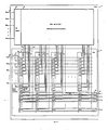
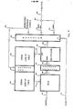
- Fig. 4 Implementation of the present invention in a micro-sequencer device is generally illustrated in Fig. 4.
- this embodiment includes a pipeline register 400 in combination with the LTPLD 424 which is comprised of a row decoder 416, EPROM look-up table 418 and dynamically programmable logic device 420 as previously shown in Fig. 3a.
- the CLOCK signal input at 414 rises to start an operational cycle, this causes the data on lines 403 to be loaded into the pipeline register 400. Shortly thereafter, that data appears at the outputs 404, 406 and 410 of the pipeline register 400.
- the output data on lines 404 drive the output pins 408 via tri-state buffers 405 when the enable signal on line 406 is true.
- the output pins remain in a high-impedance state (regardless of the values of the output data appearing on lines 404); such that this component does not define the output values.
- the registered feedback outputs on lines 410 drive the row decoder 416 which allows exactly one of 2**n word selects in the EPROM 418 to rise.
- a DPLD programming word is accessed in the EPROM to drive the dynamic programming lines 422 (lines 308 and 310 of Figs 3 and 3a) of the DPLD 420.
- the preferred delay inputs (“early" inputs) to the DPLD come from the input pins 412.
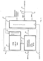
- FIG. 5 Another preferred implementation of the present invention is generally illustrated in Fig. 5.
- a second EPROM 528 has been added which shares a common address (row) decoder 516 with the previously described EPROM 518 (which is the same as 418 in Fig. 4).
- a multiplexor 532 has also been interposed in the path between the DPLD 520 and the pipeline register 500. The function of the multiplexor is as follows. The outputs of the DPLD 520 are taken to be the select controls 524 of the multiplexor 532. The selection is made among several data fields 526 which issue from the "code" EPROM 528.
- the selected data is output from the multiplexor 532 on lines 503 and proceeds to the inputs of the pipeline register 500 into which it is latched on the rising edge of CLOCK 514.
- CLK the CLOCK signal
- the incremental advantage of this approach is that the number of signals issuing from the DPLD 520 is now the relatively small number of signals (on lines 524) required to make the selection at the multiplexor 532. Since a disadvantage of the DPLD is its increased power consumption per AND term (302 of Fig. 3) and per OR term (304 of Fig. 3), a reduction in the number of required outputs (306 in Fig. 3) limits the power consumption cost of the DPLD. It is worth noting that some sacrifice in operating speed is experienced in the embodiment of Fig. 5 as compared to Fig. 4. This is due to the additional signal delay experienced in passing through the multiplexor block 532. The magnitude of this incremental delay is relatively small, however.
- FIG. 6 Another preferred implementation of the present invention is generally illustrated in Fig. 6.
- This implementation builds upon the implementation of Fig. 5 with the addition of a priority encoder 636 disposed in the signal path from the DPLD 620 to the multiplexor 632.
- the negative impact of introducing the priority encoder 636 into this path is a slight increase in the delay from the inputs 612 to the setup of the pipeline register 600.
- the positive impact of this is to significantly enhance the usefulness of the device.
- setup refers to the required time of stability of the input to a register prior to the rising edge of the next clock to that register.
- the priority encoder logic function is detailed in Fig. 7 and is described by the following truth table: where a "1" represents a true value, a "0" represents a false value, and an "x" represents a value which is either 0 or 1.
- the independent variables P3, P2 and P1 represent the three logic functions which drive the priority encoder via lines 624.
- Signals Q3, Q2, Q1 and Q0 (which are the dependent variables) represent the four outputs of the priority encoder on lines 634.
- the "else" case Q0 corresponds to the situation where none of P3, P2, or P1 are true.
- the hardware when expressed in the linear method of a software program, then the hardware must implement: CHOOSE ONE OF: p3 THEN GOTO label q3 not(p3) and p2 THEN GOTO label_q2 not(p3) and not(p2) and p1 THEN GOTO label_q1 not(p3) and not(p2) and not(p1) THEN GOTO label_q0;
- the alternative (which is the prior state of the art) is to require that the predicates p3, p2 and pl be disjoint; that is to say that no more than one of these predicates may be true at any one time.
- the user support software must ensure that this is the case if the programmed device is to function properly.
- the present invention solves the same problem by automatically choosing to GOTO label_q3 if p3 is true, to GOTO label q2 only if p2 is true but p3 is false, to GOTO label_q1 only if p3 is false and p2 is false and p1 is true, and to GOTO label_q0 only if all three of p3, p2 and p1 are false.
- This is accomplished by the use of a "priority encoder" logic block comprised of circuitry as shown in Fig. 7.
- the hardware solution allows the user support software to be straight-forward while providing the user with the familiar structures of programming language IF THEN ELSE structures in the design capture software system.
- FIG. 8 Another preferred implementation of the current invention is generally illustrated in Fig. 8 wherein to the core shown in Fig. 6, a Stack mechanism 846 has been added along with the re quired control functions 844.
- a Stack mechanism 846 has been added along with the re quired control functions 844.
- two new fields appear in the outputs of the pipeline register 800; these are Data on lines 840 and OP on lines 842.
- the OP field 842 provides instructions to the stack such as "push” and "pop.”
- LIFO last-in-first-out
- the select line 852 which comes from the control block 844 and drives the microaddress mux 838, becomes true. This causes the mux to deliver the top-of-stack value on lines 858 for the microaddress which drives the row decoder 816. If the OP is other than 000, then the select signal on lines 852 remains false and the microaddress passed through the mux 838 is the Q field on lines 810 from the pipeline register 800.
- the stack implemented in the present invention provides the same functionality as the prior art stack, but it does so with improved circuit timing.
- the innovation in the present invention is the obviation of the need to increment the stack pointer before writing the pushed data onto the stack.
- the stack pointer 906 is a four bit synchronous up down counter.
- the signal PUSHACT becomes active (true) when the OP is one of 010, 110 or 111 and the current value of the stack pointer is not 15.
- PUSHACT When PUSHACT is active, the stack pointer 906 counts up by one tick.
- the signal POPACT becomes active (true) when the OP is either 000 or 100 and the current value of the stack pointer is not 0.
- POPACT is active, the stack pointer 906 counts down by one tick.
- the stack pointer 906 will not count up past 15; rather it "sticks” at 15 for any further push attempts.
- the stack pointer 906 will also not count down below 0; rather it sticks at 0 for any further pop attempts. In this way the sequence is protected from stack overflow (the stack pointer cannot erroneously wrap around to the bottom of the stack on a push) and stack underflow (stack pointer cannot erroneously wrap around to the full stack position on a pop from an empty stack.)
- Address 0 happens to be the micro-sequence address of the boot state or initial power-on state.
- a pop from an empty stack, which is a fault, will cause the sequencer to behave as if it had been reset.
- a push to a full stack is also a fault.
- the stack of the present invention will overwrite the value on the top of the stack, but will not disturb the values below this one on the stack.
- the sequencer will recapture the lost trail of subroutine return addresses. This is not always an adequate recovery, but it is predictable and will be adequate in many cases.
- Fig. 9 the top of stack register 900 is fed from a data multiplexor 910 which corresponds to 854 in Fig. 8.
- a data multiplexor 910 which corresponds to 854 in Fig. 8.
- Two other sources of data are internal to the stack 846 as viewed in Fig. 8; these are the current top of stack and the next-to-the-top-of-stack.
- the other data sources are from the input pins 812 of Fig. 8 and the data field on lines 840 of the pipeline register 800.
- control unit 912 for the stack and stack pointer which interprets the OP field (842 in Fig. 8), buffers the clock and reset signals, and generates the select signals for the data multiplexor 910 and the POPACT and PUSHACT signals which respectively decrement and increment the stack pointer 906.
- the values in the stack which are below the top of stack are held in the stack ram file 902.
- the stack ram file receives sixteen positive read select signals (exactly one is true at a time), sixteen negative read select signals (exactly one is false at a time) and fifteen write select signals (no more than one is true at any time) which are decoded from the value of the stack pointer 906 by the stack address decoder 904 (which is composed of sixteen copies of 920).
- the "rd” cell 920 is exploded in detail 922 as shown in Fig 9a. It is important to note that each cell 920 points to one row of ram cells for reading, but points to the next higher numbered row of ram cells for writing. This is the key to the improved timing characteristics of the stack implementation of the present invention. Instead of incrementing the stack pointer, then writing the pushed data into the row of ram cells pointed to (after the stack is incremented), the write pointer in the present invention always points one row ahead of the current value of the stack pointer. In this way the pushed data may be written immediately, and the stack pointer may be incremented concurrently, to take effect after the next clock edge. On pops, the stack pointer may be decremented concurrently with the reading of the popped value off of the stack, as is previously known in the art.
- the ram cell 930 used herein is a two port (one read port, one write port) ram cell of the sort familiar to those skilled in the art. For convenience it has been exploded in detail 932 of Fig 9b.
- FIG. 10 Another preferred implementation of the present invention is generally illustrated in Fig. 10.
- the improvement over the basic core of Fig. 6, which the addition of the counter mechanism provides, is the ability to do a loop of some number of steps (lines of microcode or sequence of states) a given number of times before proceeding. An example of this is found in computer arithmetic where multiplication may be performed by shift and add.
- the loop consisting of the shift and add steps should be repeated N times for the product of two N-bit numbers to be computed. Numerous other examples of repetitive tasks which must be performed a specific number of times before proceeding will be apparent to one skilled in the art.
- Fig. 11 there is a control block 1106 which decodes the OP and buffers the reset and clock signals.
- the signal DECACT when true, enables the decrement function 1104, in which case the outputs of the decrement block 1104 (the CD7..CD0 signals) reflect a value which is the current contents of the counter register 1100 minus one.
- a data input multiplexor 1108 is controlled by a plurality of select signals from the control block 1106.
- the data which may be selected include the output of the decrement block 1104, the data field (lines 1040 in Fig. 10) of the pipeline register (1000 in Fig. 10), and the value from the top-of-stack (S7..S0) EXCLUSIVE-ORed with the data field on lines 1040 of Fig. 10 (although this is not used in the implementation of Fig. 10 since there is no stack in Fig. 10).
- a zero detection circuit 1102 monitors the output of the data selection mux 1108 immediately before this information is loaded into the counter register 1100.
- the logical output of the eight input NOR gate is sampled into a flip-flop at the same time that the counter register samples the output of the data input mux 1108.
- the output on line 1103 of the flip-flop in block 1102 is named ZF for zero-flag.
- the zero-flag on line 1072 enters the control block 1060 where a select signal on line 1052 is generated which controls the microaddress mux 1038.
- the select signal on line 1052 becomes true and the mux 1038 selects the data field on lines 1040 to be the next microaddress. If the OP field on lines 1042 has any other value, or if it is 001 and the zero-flag is true, then the Q field on lines 1010 is selected to be the next microaddress.
- This branching function is independent of the conditional multiway branching mechanism of the core inventions of Figs. 4,5,6, as was described above. It is possible to use both facilities at the same time and thus to branch to one of eight different locations.
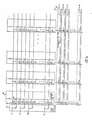
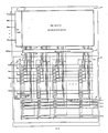
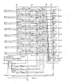
- FIG. 12 Another preferred implementation of the present invention is generally illustrated in Fig. 12. This implementation joins the logic sequencer core of Fig.6 with both the stack mechanism of Fig. 8 and Fig. 9 and the counter mechanism of Fig. 10 and Fig. 11. All of the data paths in the details of Fig. 9 and Fig. 11 are fully utilized in the implementation shown in Fig. 2.
- the control functions are grouped together now in a single control box 1260.
- the signals on lines 1252 select the data field on lines 1240 of the pipeline register 1200 to become the microaddress. If neither of the above situations obtains, then the signals on lines 1252 gate the Q field on lines 1210 to become the microaddress.
- the advantages of combining the stack and counter functions with the core logic sequencer are all of the advantages of each plus a few which arise from the interaction of the stack and counter mechanisms.
- the stack may be used to save and restore counter values.
- the higher order byte is pushed back onto the stack and 255 (full scale for an eight bit counter) is loaded into the counter to resume the count. If the higher order byte did decrement to zero, then pop the next higher order byte off of the stack, decrement and test it similarly. When all of the bytes of the counter are zero, the count is completed.
- the PUSH-COUNTER instruction automatically reloads the counter from the data field on lines 1240 of the pipeline register 1200. In this way the overhead of extended length counters is kept very small. Use of the stack also permits the use of more than one logical flag, as discussed above, by saving and restoring flags which are implemented as counter values.
- Fig 12 generally illustrates all of the features of the present invention in the form which has been reduced to practice, several elements of the embodiment which has actually built have not been described herein. These elements are individually well known in the art. These include the use of a high voltage to program the EPROM memory arrays 1218 and 1228 in Fig. 12; the use of the same set of pins twice, once for column address and then later for row address (as is done in high density memory chips for example); the use of tri-stated output pins for data entry during programming of the EPROMs 1218 and 1228; and the use of a simple serial scan path connecting all the internal flip-flops in a shift register for diagnostic and production testing purposes.
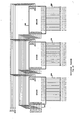
- Fig. 13 generally illustrates the method of horizontal cascading, by which several copies of an embodiment of the present invention (shown here under the Altera trade name "EPS448") may be operated in synchronized fashion so that a larger number of output signals may be driven.
- the programming of each of the EPS448s is identical to the programming of the others except for the programming of the ENABLE (lines 1205 in Fig. 12) and OUTPUT-DATA (lines 1204 in Fig. 12) fields, which differ from part to part.
- the INPUT signals, the CLOCK signal and the nRESET signal are wired in common to all of the devices. Taken together, the identical control programming and the identity of CLOCK, nRESET and the INPUT signals ensures that the multiple components will run in lock step.
- Fig. 14 generally illustrates the vertical cascading of copies of an embodiment of the present invention in order to realize a greater depth of microcode (a longer microprogram.)
- all of the INPUT signals, the CLOCK and the nRESET are wired in common.
- the OUTPUT signals are also wired together to form a tri-state bus.
- the programming is different in each device. The constraint is that only one of the devices is allowed to enable its output drivers at a time.
- Each device has an active microprogram, during which time that device drives the common output bus, and also a passive microprogram during which it does not drive the common output bus. While a device is in its passive microprogram it is waiting for the conditions which will cause it to re-enter the active microprogram. In this way the several devices cooperate to implement a larger micro-sequence than any one of them could implement alone.
Landscapes
- Engineering & Computer Science (AREA)
- Physics & Mathematics (AREA)
- Software Systems (AREA)
- Theoretical Computer Science (AREA)
- General Engineering & Computer Science (AREA)
- Mathematical Physics (AREA)
- General Physics & Mathematics (AREA)
- Computer Hardware Design (AREA)
- Computing Systems (AREA)
- Logic Circuits (AREA)
- Programmable Controllers (AREA)
Applications Claiming Priority (2)
| Application Number | Priority Date | Filing Date | Title |
|---|---|---|---|
| US23054 | 1987-03-06 | ||
| US07/023,054 US4831573A (en) | 1987-03-06 | 1987-03-06 | Programmable integrated circuit micro-sequencer device |
Publications (2)
| Publication Number | Publication Date |
|---|---|
| EP0282256A2 true EP0282256A2 (fr) | 1988-09-14 |
| EP0282256A3 EP0282256A3 (fr) | 1989-11-02 |
Family
ID=21812868
Family Applications (1)
| Application Number | Title | Priority Date | Filing Date |
|---|---|---|---|
| EP88301980A Withdrawn EP0282256A3 (fr) | 1987-03-06 | 1988-03-07 | Séquenceur de micro-instruction |
Country Status (3)
| Country | Link |
|---|---|
| US (1) | US4831573A (fr) |
| EP (1) | EP0282256A3 (fr) |
| JP (1) | JP2554914B2 (fr) |
Cited By (1)
| Publication number | Priority date | Publication date | Assignee | Title |
|---|---|---|---|---|
| GB2294184A (en) * | 1994-10-13 | 1996-04-17 | Fujitsu Ltd | Digital signal processing apparatus |
Families Citing this family (52)
| Publication number | Priority date | Publication date | Assignee | Title |
|---|---|---|---|---|
| US5349670A (en) * | 1986-07-23 | 1994-09-20 | Advanced Micro Devices, Inc. | Integrated circuit programmable sequencing element apparatus |
| US5367208A (en) | 1986-09-19 | 1994-11-22 | Actel Corporation | Reconfigurable programmable interconnect architecture |
| US4965472A (en) * | 1988-08-11 | 1990-10-23 | Cypress Semiconductor Corp. | Programmable high speed state machine with sequencing capabilities |
| CA1326303C (fr) * | 1988-08-31 | 1994-01-18 | Hideki Shutou | Structure a echelle logique etendue pour reseau logique programmable |
| US4896060A (en) * | 1988-10-31 | 1990-01-23 | Sgs-Thomson Microelectronics, Inc. | Dialer with internal option select circuit programmed with externally hardwired address |
| USRE36443E (en) * | 1988-10-31 | 1999-12-14 | Sgs-Thomson Microelectronics, Inc. | Dialer with internal option select circuit programmed with externally hardwired address |
| CA1311063C (fr) * | 1988-12-16 | 1992-12-01 | Tokumichi Murakami | Processeur de signaux numeriques |
| JP2515853Y2 (ja) * | 1989-04-06 | 1996-10-30 | 沖電気工業株式会社 | ダイナミック型pla回路 |
| US5200564A (en) * | 1990-06-29 | 1993-04-06 | Casio Computer Co., Ltd. | Digital information processing apparatus with multiple CPUs |
| US5584034A (en) * | 1990-06-29 | 1996-12-10 | Casio Computer Co., Ltd. | Apparatus for executing respective portions of a process by main and sub CPUS |
| JP2544020B2 (ja) * | 1990-11-19 | 1996-10-16 | 川崎製鉄株式会社 | プログラマブル論理素子 |
| US5359570A (en) * | 1992-11-13 | 1994-10-25 | Silicon Storage Technology, Inc. | Solid state peripheral storage device |
| US5361373A (en) * | 1992-12-11 | 1994-11-01 | Gilson Kent L | Integrated circuit computing device comprising a dynamically configurable gate array having a microprocessor and reconfigurable instruction execution means and method therefor |
| GB9303084D0 (en) * | 1993-02-16 | 1993-03-31 | Inmos Ltd | Programmable logic circuit |
| US5493689A (en) * | 1993-03-01 | 1996-02-20 | International Business Machines Corporation | System for configuring an event driven interface including control blocks defining good loop locations in a memory which represent detection of a characteristic pattern |
| US5432467A (en) * | 1993-05-07 | 1995-07-11 | Altera Corporation | Programmable logic device with low power voltage level translator |
| US5352940A (en) * | 1993-05-27 | 1994-10-04 | Altera Corporation | Ram convertible look-up table based macrocell for PLDs |
| DE4430195B4 (de) * | 1993-12-13 | 2004-09-23 | Hewlett-Packard Co. (N.D.Ges.D.Staates Delaware), Palo Alto | Verfahren zur Auswertung von Booleschen Ausdrücken |
| US5471597A (en) * | 1993-12-23 | 1995-11-28 | Unisys Corporation | System and method for executing branch instructions wherein branch target addresses are dynamically selectable under programmer control from writable branch address tables |
| US5442577A (en) * | 1994-03-08 | 1995-08-15 | Exponential Technology, Inc. | Sign-extension of immediate constants in an alu |
| US5781457A (en) * | 1994-03-08 | 1998-07-14 | Exponential Technology, Inc. | Merge/mask, rotate/shift, and boolean operations from two instruction sets executed in a vectored mux on a dual-ALU |
| US5600845A (en) * | 1994-07-27 | 1997-02-04 | Metalithic Systems Incorporated | Integrated circuit computing device comprising a dynamically configurable gate array having a microprocessor and reconfigurable instruction execution means and method therefor |
| US5442306A (en) * | 1994-09-09 | 1995-08-15 | At&T Corp. | Field programmable gate array using look-up tables, multiplexers and decoders |
| US5838165A (en) * | 1996-08-21 | 1998-11-17 | Chatter; Mukesh | High performance self modifying on-the-fly alterable logic FPGA, architecture and method |
| GB2317248B (en) * | 1996-09-02 | 2001-08-15 | Siemens Plc | Floating point number data processing means |
| JP3403614B2 (ja) * | 1997-06-13 | 2003-05-06 | 富士通株式会社 | 動的な資源利用機能を備えたデータ処理システム |
| US6209077B1 (en) * | 1998-12-21 | 2001-03-27 | Sandia Corporation | General purpose programmable accelerator board |
| JP2001216152A (ja) * | 2000-01-28 | 2001-08-10 | Rooran:Kk | 論理集積回路及びそのcpuコアのソースを記録したコンピュータ読み取り可能な記録媒体 |
| US6268807B1 (en) * | 2000-02-01 | 2001-07-31 | Lara Technology, Inc. | Priority encoder/read only memory (ROM) combination |
| US6445209B1 (en) * | 2000-05-05 | 2002-09-03 | Xilinx, Inc. | FPGA lookup table with NOR gate write decoder and high speed read decoder |
| JP2002082813A (ja) | 2000-06-26 | 2002-03-22 | Nippon Computer:Kk | プログラムロジック装置 |
| US7376206B1 (en) * | 2000-11-06 | 2008-05-20 | Qualcomm Incorporated | Method and apparatus for adjusting the phase of a received signal |
| US6466505B1 (en) | 2001-05-02 | 2002-10-15 | Cypress Semiconductor Corp. | Flexible input structure for an embedded memory |
| US6621295B1 (en) * | 2002-01-15 | 2003-09-16 | Xilinx, Inc. | Reconfigurable priority encoding |
| US6992503B2 (en) | 2002-07-08 | 2006-01-31 | Viciciv Technology | Programmable devices with convertibility to customizable devices |
| US7112994B2 (en) * | 2002-07-08 | 2006-09-26 | Viciciv Technology | Three dimensional integrated circuits |
| US8643162B2 (en) | 2007-11-19 | 2014-02-04 | Raminda Udaya Madurawe | Pads and pin-outs in three dimensional integrated circuits |
| US6958625B1 (en) | 2003-07-10 | 2005-10-25 | Lattice Semiconductor Corporation | Programmable logic device with hardwired microsequencer |
| US20050071730A1 (en) * | 2003-09-30 | 2005-03-31 | Lattice Semiconductor Corporation | Continuous self-verify of configuration memory in programmable logic devices |
| US7030651B2 (en) | 2003-12-04 | 2006-04-18 | Viciciv Technology | Programmable structured arrays |
| US7606969B2 (en) * | 2003-12-05 | 2009-10-20 | Davinder Aggarwal | Programmable logic devices |
| US20060080632A1 (en) * | 2004-09-30 | 2006-04-13 | Mathstar, Inc. | Integrated circuit layout having rectilinear structure of objects |
| EP1806847B1 (fr) * | 2004-10-28 | 2010-02-17 | IP Flex Inc. | Dispositif de traitement de donnees presentant un circuit logique reconfigurable |
| US7257750B1 (en) | 2005-01-13 | 2007-08-14 | Lattice Semiconductor Corporation | Self-verification of configuration memory in programmable logic devices |
| US20070247189A1 (en) * | 2005-01-25 | 2007-10-25 | Mathstar | Field programmable semiconductor object array integrated circuit |
| US8024549B2 (en) * | 2005-03-04 | 2011-09-20 | Mtekvision Co., Ltd. | Two-dimensional processor array of processing elements |
| US7596744B1 (en) | 2006-02-24 | 2009-09-29 | Lattice Semiconductor Corporation | Auto recovery from volatile soft error upsets (SEUs) |
| US8065574B1 (en) | 2007-06-08 | 2011-11-22 | Lattice Semiconductor Corporation | Soft error detection logic testing systems and methods |
| US20090144595A1 (en) * | 2007-11-30 | 2009-06-04 | Mathstar, Inc. | Built-in self-testing (bist) of field programmable object arrays |
| US8230375B2 (en) | 2008-09-14 | 2012-07-24 | Raminda Udaya Madurawe | Automated metal pattern generation for integrated circuits |
| US8661394B1 (en) | 2008-09-24 | 2014-02-25 | Iowa State University Research Foundation, Inc. | Depth-optimal mapping of logic chains in reconfigurable fabrics |
| US8438522B1 (en) | 2008-09-24 | 2013-05-07 | Iowa State University Research Foundation, Inc. | Logic element architecture for generic logic chains in programmable devices |
Citations (4)
| Publication number | Priority date | Publication date | Assignee | Title |
|---|---|---|---|---|
| EP0114194A2 (fr) * | 1982-12-23 | 1984-08-01 | International Business Machines Corporation | Mécanisme de génération de micro-mots utilisant un réseau à logique programmable séparé avec décision de branchement |
| EP0116287A2 (fr) * | 1983-01-11 | 1984-08-22 | BURROUGHS CORPORATION (a Delaware corporation) | PLA reprogrammable dynamique |
| US4490812A (en) * | 1982-09-30 | 1984-12-25 | Mostek Corporation | User reprogrammable programmed logic array |
| GB2171231A (en) * | 1985-02-14 | 1986-08-20 | Intel Corp | Software programmable logic array |
Family Cites Families (6)
| Publication number | Priority date | Publication date | Assignee | Title |
|---|---|---|---|---|
| JPS5147335A (ja) * | 1974-10-21 | 1976-04-22 | Nippon Electric Co | Johoshorisochi |
| US4578771A (en) * | 1980-12-29 | 1986-03-25 | International Business Machines Corporation | Dynamically reprogrammable array logic system |
| JPS5928727A (ja) * | 1982-08-09 | 1984-02-15 | Nippon Telegr & Teleph Corp <Ntt> | プログラム可能論理アレイ |
| US4677318A (en) * | 1985-04-12 | 1987-06-30 | Altera Corporation | Programmable logic storage element for programmable logic devices |
| US4697105A (en) * | 1986-07-23 | 1987-09-29 | American Telephone And Telegraph Company, At&T Bell Laboratories | CMOS programmable logic array |
| US4721868A (en) * | 1986-09-23 | 1988-01-26 | Advanced Micro Devices, Inc. | IC input circuitry programmable for realizing multiple functions from a single input |
-
1987
- 1987-03-06 US US07/023,054 patent/US4831573A/en not_active Expired - Lifetime
-
1988
- 1988-03-07 JP JP63053423A patent/JP2554914B2/ja not_active Expired - Fee Related
- 1988-03-07 EP EP88301980A patent/EP0282256A3/fr not_active Withdrawn
Patent Citations (4)
| Publication number | Priority date | Publication date | Assignee | Title |
|---|---|---|---|---|
| US4490812A (en) * | 1982-09-30 | 1984-12-25 | Mostek Corporation | User reprogrammable programmed logic array |
| EP0114194A2 (fr) * | 1982-12-23 | 1984-08-01 | International Business Machines Corporation | Mécanisme de génération de micro-mots utilisant un réseau à logique programmable séparé avec décision de branchement |
| EP0116287A2 (fr) * | 1983-01-11 | 1984-08-22 | BURROUGHS CORPORATION (a Delaware corporation) | PLA reprogrammable dynamique |
| GB2171231A (en) * | 1985-02-14 | 1986-08-20 | Intel Corp | Software programmable logic array |
Cited By (2)
| Publication number | Priority date | Publication date | Assignee | Title |
|---|---|---|---|---|
| GB2294184A (en) * | 1994-10-13 | 1996-04-17 | Fujitsu Ltd | Digital signal processing apparatus |
| GB2294184B (en) * | 1994-10-13 | 1999-05-26 | Fujitsu Ltd | Signal processing apparatus |
Also Published As
| Publication number | Publication date |
|---|---|
| US4831573A (en) | 1989-05-16 |
| JP2554914B2 (ja) | 1996-11-20 |
| JPS63308411A (ja) | 1988-12-15 |
| EP0282256A3 (fr) | 1989-11-02 |
Similar Documents
| Publication | Publication Date | Title |
|---|---|---|
| US4831573A (en) | Programmable integrated circuit micro-sequencer device | |
| EP0582660B1 (fr) | Dispositif et procede de multiplexage de broches permettant de programmer des unites logiques a l'interieur d'un systeme | |
| EP0102242B1 (fr) | Appareil de traitement de données | |
| US4876640A (en) | Logic controller having programmable logic "and" array using a programmable gray-code counter | |
| US5394031A (en) | Apparatus and method to improve programming speed of field programmable gate arrays | |
| JP3471088B2 (ja) | 改良されたプログラマブル論理セルアレイアーキテクチャ | |
| EP0840455B1 (fr) | Macrocellule accessible par microprocesseur | |
| US5302866A (en) | Input circuit block and method for PLDs with register clock enable selection | |
| US4506341A (en) | Interlaced programmable logic array having shared elements | |
| JPS6361691B2 (fr) | ||
| KR900005282B1 (ko) | 직접 회로 구조 | |
| US4383304A (en) | Programmable bit shift circuit | |
| US4504904A (en) | Binary logic structure employing programmable logic arrays and useful in microword generation apparatus | |
| US5261116A (en) | Programmable, expandable controller with flexible I/O | |
| US5497107A (en) | Multiple, selectable PLAS having shared inputs and outputs | |
| EP0167959B1 (fr) | Traitement pour registres de vecteur de calculateur | |
| US5298803A (en) | Programmable logic device having low power microcells with selectable registered and combinatorial output signals | |
| EP0143351A2 (fr) | Dispositif mémoire à fonction d'inter-échange de registres | |
| EP0238230B1 (fr) | Dispositif logique programmable | |
| Bunyk et al. | Design of an RSFQ microprocessor | |
| EP0239276A2 (fr) | ALU pour processeur en tranches avec voie multiplexée de contournement | |
| Manzoul et al. | Overcurrent relay on a FPGA chip | |
| USRE32858E (en) | Stored-program control machine | |
| US5018092A (en) | Stack-type arithmetic circuit | |
| JP2922963B2 (ja) | シーケンスコントローラ |
Legal Events
| Date | Code | Title | Description |
|---|---|---|---|
| PUAI | Public reference made under article 153(3) epc to a published international application that has entered the european phase |
Free format text: ORIGINAL CODE: 0009012 |
|
| AK | Designated contracting states |
Kind code of ref document: A2 Designated state(s): DE FR GB IT NL |
|
| PUAL | Search report despatched |
Free format text: ORIGINAL CODE: 0009013 |
|
| AK | Designated contracting states |
Kind code of ref document: A3 Designated state(s): DE FR GB IT NL |
|
| 17P | Request for examination filed |
Effective date: 19900313 |
|
| 17Q | First examination report despatched |
Effective date: 19920624 |
|
| STAA | Information on the status of an ep patent application or granted ep patent |
Free format text: STATUS: THE APPLICATION HAS BEEN WITHDRAWN |
|
| 18W | Application withdrawn |
Withdrawal date: 19921230 |