EP0282090A1 - Fraise à plaquettes - Google Patents
Fraise à plaquettes Download PDFInfo
- Publication number
- EP0282090A1 EP0282090A1 EP88103919A EP88103919A EP0282090A1 EP 0282090 A1 EP0282090 A1 EP 0282090A1 EP 88103919 A EP88103919 A EP 88103919A EP 88103919 A EP88103919 A EP 88103919A EP 0282090 A1 EP0282090 A1 EP 0282090A1
- Authority
- EP
- European Patent Office
- Prior art keywords
- insert holder
- wedge
- cutter head
- insert
- head according
- Prior art date
- Legal status (The legal status is an assumption and is not a legal conclusion. Google has not performed a legal analysis and makes no representation as to the accuracy of the status listed.)
- Granted
Links
Images

Classifications
-
- B—PERFORMING OPERATIONS; TRANSPORTING
- B23—MACHINE TOOLS; METAL-WORKING NOT OTHERWISE PROVIDED FOR
- B23C—MILLING
- B23C5/00—Milling-cutters
- B23C5/16—Milling-cutters characterised by physical features other than shape
- B23C5/20—Milling-cutters characterised by physical features other than shape with removable cutter bits or teeth or cutting inserts
- B23C5/22—Securing arrangements for bits or teeth or cutting inserts
- B23C5/24—Securing arrangements for bits or teeth or cutting inserts adjustable
- B23C5/2462—Securing arrangements for bits or teeth or cutting inserts adjustable the adjusting means being oblique surfaces
-
- B—PERFORMING OPERATIONS; TRANSPORTING
- B23—MACHINE TOOLS; METAL-WORKING NOT OTHERWISE PROVIDED FOR
- B23C—MILLING
- B23C5/00—Milling-cutters
- B23C5/16—Milling-cutters characterised by physical features other than shape
- B23C5/20—Milling-cutters characterised by physical features other than shape with removable cutter bits or teeth or cutting inserts
- B23C5/202—Plate-like cutting inserts with special form
-
- B—PERFORMING OPERATIONS; TRANSPORTING
- B23—MACHINE TOOLS; METAL-WORKING NOT OTHERWISE PROVIDED FOR
- B23C—MILLING
- B23C5/00—Milling-cutters
- B23C5/16—Milling-cutters characterised by physical features other than shape
- B23C5/20—Milling-cutters characterised by physical features other than shape with removable cutter bits or teeth or cutting inserts
- B23C5/22—Securing arrangements for bits or teeth or cutting inserts
- B23C5/2265—Securing arrangements for bits or teeth or cutting inserts by means of a wedge
- B23C5/2278—Securing arrangements for bits or teeth or cutting inserts by means of a wedge for plate-like cutting inserts fitted on an intermediate carrier, e.g. shank fixed in the cutter body
-
- B—PERFORMING OPERATIONS; TRANSPORTING
- B23—MACHINE TOOLS; METAL-WORKING NOT OTHERWISE PROVIDED FOR
- B23C—MILLING
- B23C5/00—Milling-cutters
- B23C5/16—Milling-cutters characterised by physical features other than shape
- B23C5/20—Milling-cutters characterised by physical features other than shape with removable cutter bits or teeth or cutting inserts
- B23C5/22—Securing arrangements for bits or teeth or cutting inserts
- B23C5/24—Securing arrangements for bits or teeth or cutting inserts adjustable
- B23C5/2472—Securing arrangements for bits or teeth or cutting inserts adjustable the adjusting means being screws
-
- B—PERFORMING OPERATIONS; TRANSPORTING
- B23—MACHINE TOOLS; METAL-WORKING NOT OTHERWISE PROVIDED FOR
- B23C—MILLING
- B23C5/00—Milling-cutters
- B23C5/16—Milling-cutters characterised by physical features other than shape
- B23C5/20—Milling-cutters characterised by physical features other than shape with removable cutter bits or teeth or cutting inserts
- B23C5/22—Securing arrangements for bits or teeth or cutting inserts
- B23C5/24—Securing arrangements for bits or teeth or cutting inserts adjustable
- B23C5/2489—Securing arrangements for bits or teeth or cutting inserts adjustable where the adjustment is made by changing the inclination of the inserts
-
- B—PERFORMING OPERATIONS; TRANSPORTING
- B23—MACHINE TOOLS; METAL-WORKING NOT OTHERWISE PROVIDED FOR
- B23C—MILLING
- B23C2200/00—Details of milling cutting inserts
- B23C2200/16—Supporting or bottom surfaces
- B23C2200/165—Supporting or bottom surfaces with one or more grooves
-
- B—PERFORMING OPERATIONS; TRANSPORTING
- B23—MACHINE TOOLS; METAL-WORKING NOT OTHERWISE PROVIDED FOR
- B23C—MILLING
- B23C2200/00—Details of milling cutting inserts
- B23C2200/20—Top or side views of the cutting edge
- B23C2200/201—Details of the nose radius and immediately surrounding areas
-
- Y—GENERAL TAGGING OF NEW TECHNOLOGICAL DEVELOPMENTS; GENERAL TAGGING OF CROSS-SECTIONAL TECHNOLOGIES SPANNING OVER SEVERAL SECTIONS OF THE IPC; TECHNICAL SUBJECTS COVERED BY FORMER USPC CROSS-REFERENCE ART COLLECTIONS [XRACs] AND DIGESTS
- Y10—TECHNICAL SUBJECTS COVERED BY FORMER USPC
- Y10T—TECHNICAL SUBJECTS COVERED BY FORMER US CLASSIFICATION
- Y10T407/00—Cutters, for shaping
- Y10T407/19—Rotary cutting tool
- Y10T407/1906—Rotary cutting tool including holder [i.e., head] having seat for inserted tool
- Y10T407/1908—Face or end mill
- Y10T407/1912—Tool adjustable relative to holder
- Y10T407/1914—Radially
- Y10T407/1916—And axially
- Y10T407/1918—Selectively
-
- Y—GENERAL TAGGING OF NEW TECHNOLOGICAL DEVELOPMENTS; GENERAL TAGGING OF CROSS-SECTIONAL TECHNOLOGIES SPANNING OVER SEVERAL SECTIONS OF THE IPC; TECHNICAL SUBJECTS COVERED BY FORMER USPC CROSS-REFERENCE ART COLLECTIONS [XRACs] AND DIGESTS
- Y10—TECHNICAL SUBJECTS COVERED BY FORMER USPC
- Y10T—TECHNICAL SUBJECTS COVERED BY FORMER US CLASSIFICATION
- Y10T407/00—Cutters, for shaping
- Y10T407/19—Rotary cutting tool
- Y10T407/1906—Rotary cutting tool including holder [i.e., head] having seat for inserted tool
- Y10T407/1932—Rotary cutting tool including holder [i.e., head] having seat for inserted tool with means to fasten tool seat to holder
-
- Y—GENERAL TAGGING OF NEW TECHNOLOGICAL DEVELOPMENTS; GENERAL TAGGING OF CROSS-SECTIONAL TECHNOLOGIES SPANNING OVER SEVERAL SECTIONS OF THE IPC; TECHNICAL SUBJECTS COVERED BY FORMER USPC CROSS-REFERENCE ART COLLECTIONS [XRACs] AND DIGESTS
- Y10—TECHNICAL SUBJECTS COVERED BY FORMER USPC
- Y10T—TECHNICAL SUBJECTS COVERED BY FORMER US CLASSIFICATION
- Y10T407/00—Cutters, for shaping
- Y10T407/22—Cutters, for shaping including holder having seat for inserted tool
- Y10T407/2214—Cutters, for shaping including holder having seat for inserted tool with separate means to adjust tool to and fro relative to holder
- Y10T407/222—Cutters, for shaping including holder having seat for inserted tool with separate means to adjust tool to and fro relative to holder by moving tool seat
-
- Y—GENERAL TAGGING OF NEW TECHNOLOGICAL DEVELOPMENTS; GENERAL TAGGING OF CROSS-SECTIONAL TECHNOLOGIES SPANNING OVER SEVERAL SECTIONS OF THE IPC; TECHNICAL SUBJECTS COVERED BY FORMER USPC CROSS-REFERENCE ART COLLECTIONS [XRACs] AND DIGESTS
- Y10—TECHNICAL SUBJECTS COVERED BY FORMER USPC
- Y10T—TECHNICAL SUBJECTS COVERED BY FORMER US CLASSIFICATION
- Y10T407/00—Cutters, for shaping
- Y10T407/22—Cutters, for shaping including holder having seat for inserted tool
- Y10T407/2222—Tool adjustable relative to holder
- Y10T407/2244—Tool adjustable relative to holder by movement of seat relative to holder
- Y10T407/2246—Pivoted seat
Definitions
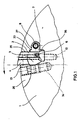
- the invention relates to a cutter head with a substantially cylindrical base body, which is provided on its circumferential area with a plurality of grooves open to the end face and to a part of the outer circumferential surface, in each of which a cutting plate carrier provided with a cutting plate is arranged, behind in the circumferential direction of rotation
- Insert holder is provided with an axially displaceable radial adjustment wedge with its active surfaces against the insert holder and against the base body, and an axial adjustment wedge arranged axially behind the insert holder and displaceable in the radial direction by means of a differential screw, and a radially adjustable clamping wedge is provided in front of the insert holder in the circumferential direction of rotation.
- Cutter heads of the type mentioned at the outset which are primarily used as milling tools in metalworking, can be used for a wide variety of rotational speeds, the rotational speed to be provided in each case depending on the material to be machined and the type of cutting inserts. It must be ensured in the entire speed range of the cutter head that the respective cutting inserts can be adjusted with maximum precision with regard to the position of their cutting edges relative to the main body of the cutter head. Particularly in the case of integrated production systems with automatic production monitoring, automatic tool change and automatic wear monitoring, it is of particular importance that the cutting inserts maintain their position relative to the base body during the milling process.
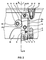
- the insert holder is designed such that its contact surface, which brings the clamping wedge into contact, extends from a region lying in the circumferential direction, lying in the axial direction at the rear, to a region lying further forward in the circumferential direction, lying in the axial direction at the front. It is thus ensured in a particularly simple manner that the insert holder is brought into abutment against the walls of the groove of the base body by the clamping wedge in the manner mentioned at the beginning.
- Such a contact surface 21a which has a strip-like elevation, proves to be advantageous in the context of the invention in that an expansion of the groove 20 in which the insert holder 2 is arranged is prevented when the clamping wedge 13 is tightened, since the surface pressure between the clamping wedge 13 and the strip-like raised area of the contact surface 21a is substantially improved.
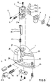
- FIG. 2 also shows the radial adjustment wedge 7 and the differential screw 8 used for its adjustment in a broken line. Furthermore, FIG. 2 shows one of two adjustment screws 6, with the aid of which the insert cage 3 can be pivoted relative to the insert holder 2. A clamping screw 9 is provided in the central area of the insert holder 2, which as will be described below in connection with FIG. 3, serves to bias the wedge prism arrangement. Furthermore, FIG. 2 shows, partly in section and offset by 90 °, a groove 25 which is formed in a ring shape in the edge region of the base body 1 and in which a plurality of balancing bodies 15, shown in detail in FIG. 3, are arranged. The enlargement of the groove 25 required for inserting the balancing body 15 is closed by means of a locking screw 17 shown in FIG. 2.
- Fig. 3 shows a section along the line A-A of Fig. 2. It can be clearly seen that the groove 20 extends only over a portion of the axial thickness of the base body 1. At the axially further back end, the recess 29 is shown, in which the axial adjustment wedge 11 is arranged.
- the separating surface between the axial adjustment wedge 11 and the insert holder 2 is in the form of a plane perpendicular to the central axis of the base body 1, so that the insert holder 2 in the radial direction, i. H. 3 to the right, is displaceable without the axial adjustment wedge 11 having to be actuated.
- the axial adjustment wedge 11 is displaced in a substantially radial direction by means of the differential screw 12.
- the first prism 10a can be prestressed in the direction of the second and the third prism, so that when the tightening screw 9 is screwed in a radially outward force is applied to the insert holder 2.
- the wedge prism arrangement 10 ensures that the insert holder 2, with its radially inner end region, is always in a tight, prestressed abutment against the wall of the groove 20. Like the action of the clamping wedge 13, this leads to a pre-tensioning of the insert holder 2, thereby preventing widening and loosening under the influence of the centrifugal force occurring at high rotational speeds of the base body 1.
- Fig. 3 further shows that the tip angle of the first prism 10a is substantially 90 °, while the angle between the radially inner region of the groove 20 and the surfaces of the second and third prism contacting the insert holder 2 are formed at an acute angle.
- the insert cage 3 is also shown in side view, which can be pivoted about an axis by means of the two adjusting screws 6, which essentially corresponds to the axis of rotation of the fastening screw 5 for the insert 4.
- the two adjusting screws 6 are guided in threaded recesses of the insert holder 2 and are located with their inner end region in contact with a stop 32 of the insert cage 3, which is in an essentially arcuate recess 33 of the insert holder 2 is pivotally received.
- the insert cage 3 is pivoted relative to the insert holder 2.
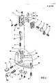
- Fig. 4 shows an exploded view of an embodiment of the cutter head according to the invention.
- the individual parts of the cutter head shown in the exploded view correspond to the parts described in FIGS. 1 to 3 except for the attachment of the cutting plate 4 to the cutting plate cage 3.
- Fig. 4 particularly clearly shows the design of the axial adjustment wedge 11, the tensioning wedge 13 and the radial adjustment wedge 7. This has a radially inner edge which is arranged parallel to the central axis of the base body 1 and is in contact with an extension 35 of the insert holder 2, which is also arranged parallel to the central axis of the base body 1.
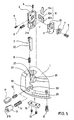
- FIGS. 5 and 6 differ from the exemplary embodiment according to FIG. 4 only in the attachment of the cutting plate 4 to the cutting plate cage 3.
- both the cutting plate cage 3 and the cutting plate 4 are provided with a Tongue-and-groove connection 24 provided, by means of which the cutting plate 4 can be secured against rotation in a particularly effective manner on the cutting plate cage 3.
- the cutting plate 4 is fastened by means of the fastening screw 5, which also serves to mount the cutting plate cage 3 on the cutting plate carrier 2.
Priority Applications (1)
| Application Number | Priority Date | Filing Date | Title |
|---|---|---|---|
| AT88103919T ATE77281T1 (de) | 1987-03-12 | 1988-03-11 | Messerkopf. |
Applications Claiming Priority (2)
| Application Number | Priority Date | Filing Date | Title |
|---|---|---|---|
| DE19873708034 DE3708034A1 (de) | 1987-03-12 | 1987-03-12 | Messerkopf |
| DE3708034 | 1987-03-12 |
Publications (2)
| Publication Number | Publication Date |
|---|---|
| EP0282090A1 true EP0282090A1 (fr) | 1988-09-14 |
| EP0282090B1 EP0282090B1 (fr) | 1992-06-17 |
Family
ID=6322915
Family Applications (1)
| Application Number | Title | Priority Date | Filing Date |
|---|---|---|---|
| EP88103919A Expired - Lifetime EP0282090B1 (fr) | 1987-03-12 | 1988-03-11 | Fraise à plaquettes |
Country Status (8)
| Country | Link |
|---|---|
| US (1) | US4848977A (fr) |
| EP (1) | EP0282090B1 (fr) |
| JP (1) | JPH0825089B2 (fr) |
| KR (1) | KR880010852A (fr) |
| AT (1) | ATE77281T1 (fr) |
| CA (1) | CA1289741C (fr) |
| DE (2) | DE3708034A1 (fr) |
| ES (1) | ES2032886T3 (fr) |
Cited By (10)
| Publication number | Priority date | Publication date | Assignee | Title |
|---|---|---|---|---|
| US4938638A (en) * | 1988-03-11 | 1990-07-03 | Sandvik Ab | Milling cutter |
| US5529439A (en) * | 1993-04-27 | 1996-06-25 | Sandvik Ab | Milling cutter head with serrated cartridges |
| WO1998047654A1 (fr) * | 1997-04-22 | 1998-10-29 | Kennametal Inc. | Porte-outil de chanfreinage a angle d'attaque reglable |
| US5863156A (en) * | 1996-03-19 | 1999-01-26 | Iscar Ltd. | Cutting tool assembly |
| WO2010026056A1 (fr) * | 2008-09-04 | 2010-03-11 | Komet Group Gmbh | Outil d'usinage doté d'une plaquette de coupe réglable |
| JP2011519736A (ja) * | 2008-05-08 | 2011-07-14 | ケンナメタル インコーポレイテッド | 被加工物のターンターンブローチ加工または外部フライス加工用工具 |
| US20110188951A1 (en) * | 2008-05-30 | 2011-08-04 | Kennametal Inc. | Tool Cassette |
| US20150209867A1 (en) * | 2014-01-16 | 2015-07-30 | Kennametal Inc. | Cartridge for a cutting insert |
| WO2015125130A1 (fr) * | 2014-02-19 | 2015-08-27 | Iscar Ltd. | Outil de coupe avec angle de coupe de plaquette réglable |
| WO2020212412A1 (fr) * | 2019-04-18 | 2020-10-22 | Gühring KG | Outil d'usinage par enlèvement de copeaux avec un insert de coupe fixé de manière ajustable. |
Families Citing this family (31)
| Publication number | Priority date | Publication date | Assignee | Title |
|---|---|---|---|---|
| DE3922963C2 (de) * | 1989-07-12 | 1994-06-01 | Widia Heinlein Gmbh | Drehräumwerkzeug |
| US5123787A (en) * | 1991-02-25 | 1992-06-23 | Gte Valenite Corporation | Machining tool |
| US5156501A (en) * | 1991-08-07 | 1992-10-20 | Gte Valenite Corporation | Adjustable torsion bar cartridge for face mills |
| US5147157A (en) * | 1991-08-07 | 1992-09-15 | Gte Valenite Corporation | Adjustable leaf spring cartridge for face mills |
| US5336026A (en) * | 1992-12-21 | 1994-08-09 | Valenite Inc. | Adjustable boring bar |
| DE4307630B4 (de) * | 1993-03-11 | 2005-02-17 | Gesellschaft für Fertigungstechnik und Entwicklung Schmalkalden/Chemnitz mbH | Fräser mit einstellbarem Schneideinsatz |
| SE512751C2 (sv) * | 1997-04-11 | 2000-05-08 | Sandvik Ab | Skärande verktyg |
| DE10012818B4 (de) * | 2000-03-16 | 2006-04-06 | Wilhelm Fette Gmbh | Plan- oder Eckfräser |
| DE10234030A1 (de) * | 2002-07-26 | 2004-02-05 | Widia Gmbh | Schneidwerkzeug für die spanabhebende Bearbeitung |
| PL204389B1 (pl) * | 2002-08-13 | 2010-01-29 | Kennametal Widia Gmbh & Co Kg | Narzędzie o kształcie tarczy względnie o kształcie listwy |
| JP4413501B2 (ja) * | 2003-01-31 | 2010-02-10 | 三菱レイヨン株式会社 | 回転切削ユニット、回転ヘッド及び刃物ブロック |
| IL157032A (en) * | 2003-07-21 | 2007-10-31 | Moshe Elbaz | Cutting head for rotary cutting tool |
| WO2007022743A1 (fr) * | 2005-08-23 | 2007-03-01 | Kennametal Widia Produktions Gmbh & Co. Kg | Tete de fraisage |
| SE530082C2 (sv) * | 2006-05-31 | 2008-02-26 | Seco Tools Ab | Skärverktyg med inrättning för bestämmande av läget hos skär samt förfarande för fixering av ett skär i valbart läge |
| IL177613A0 (en) * | 2006-08-21 | 2006-12-10 | Iscar Ltd | A cutting insert adjustment device |
| CN101553335A (zh) * | 2006-12-06 | 2009-10-07 | 雷高费克斯股份公司 | 平衡工具接头的方法和装置 |
| US8327742B1 (en) * | 2008-03-07 | 2012-12-11 | Lockheed Martin Corporation | Diamond tool micro-height-adjuster within a multi-tool rotating head |
| JP4947384B2 (ja) * | 2008-08-07 | 2012-06-06 | 大学共同利用機関法人 高エネルギー加速器研究機構 | 超伝導高周波加速空洞の製造方法 |
| CN101664822B (zh) * | 2009-09-11 | 2011-08-31 | 江西瑞林装备技术有限公司 | 铜阳极板铣刀装置 |
| DE102012004654A1 (de) * | 2011-03-29 | 2012-10-04 | Kennametal India Limited | Schneideinheit, Verfahren zur Änderung des Spanwinkels der Schneideinheit und Verfahren zu ihrem Zusammenbau |
| DE102012018643A1 (de) * | 2012-09-17 | 2014-04-10 | MAPAL Fabrik für Präzisionswerkzeuge Dr. Kress KG | Werkzeug zur spanenden Bearbeitung von Werkstücken |
| US9375723B2 (en) | 2013-04-29 | 2016-06-28 | Vermeer Manufacturing Company | Cutter assembly and adjustable cutter for use in comminuting apparatus |
| US9205499B2 (en) | 2013-09-11 | 2015-12-08 | Kennametal Inc. | Cutting insert with finishing and roughing cutting edges |
| US9211590B2 (en) | 2013-09-20 | 2015-12-15 | Kennametal Inc. | Screw head wedge clamp assembly for cutting tool |
| US9211589B2 (en) | 2013-10-08 | 2015-12-15 | Kennametal Inc. | Double-sided, nonagon cutting insert |
| US9475138B2 (en) | 2014-01-22 | 2016-10-25 | Kennametal Inc. | Cutting tool having insert pocket with cantilevered member |
| EP3069809B1 (fr) * | 2014-05-15 | 2021-10-20 | Tungaloy Corporation | Mécanisme de fixation d'insert et outil de coupe |
| JP6467049B2 (ja) * | 2015-06-25 | 2019-02-06 | 京セラ株式会社 | 切削工具及び切削加工物の製造方法 |
| US10549353B2 (en) * | 2017-05-10 | 2020-02-04 | Tungaloy Corporation | Cutting tool |
| US11338373B2 (en) * | 2018-01-08 | 2022-05-24 | Osg Corporation | Insert and body |
| CN115055746B (zh) * | 2022-07-28 | 2022-12-23 | 成都晶脉精密机械有限公司 | 一种旋铣刀盘及铣床 |
Citations (2)
| Publication number | Priority date | Publication date | Assignee | Title |
|---|---|---|---|---|
| EP0042667A2 (fr) * | 1980-06-24 | 1981-12-30 | General Electric Company | Ensemble de coins de positionnement réglable axialement et radialement pour une plaquette de coupe interchangeable d'un outil de coupe |
| DE3140905A1 (de) * | 1981-06-26 | 1983-05-05 | Sitzmann & Heinlein Gmbh, 8502 Zirndorf | "planmesserkopf, insbesondere schlichtkopf" |
Family Cites Families (5)
| Publication number | Priority date | Publication date | Assignee | Title |
|---|---|---|---|---|
| US1050455A (en) * | 1911-09-02 | 1913-01-14 | Crescent Machine Company | Cutter-head-knife-adjusting wrench. |
| US3882582A (en) * | 1973-04-18 | 1975-05-13 | Thurston V Williams | Adjustable bit holder |
| DE3317916A1 (de) * | 1983-05-17 | 1984-11-22 | Walter Kieninger KG Hartmetallwerkzeugfabrik, 7630 Lahr | Fraeswerkzeug |
| US4547100A (en) * | 1983-09-28 | 1985-10-15 | The Valeron Corporation | Adjustable milling cutter |
| SE454490B (sv) * | 1984-07-05 | 1988-05-09 | Seco Tools Ab | Fres med instellbar kassett |
-
1987
- 1987-03-12 DE DE19873708034 patent/DE3708034A1/de not_active Withdrawn
-
1988
- 1988-03-07 US US07/164,520 patent/US4848977A/en not_active Expired - Lifetime
- 1988-03-09 CA CA000560955A patent/CA1289741C/fr not_active Expired - Fee Related
- 1988-03-11 AT AT88103919T patent/ATE77281T1/de not_active IP Right Cessation
- 1988-03-11 DE DE8888103919T patent/DE3871997D1/de not_active Expired - Fee Related
- 1988-03-11 JP JP63058145A patent/JPH0825089B2/ja not_active Expired - Lifetime
- 1988-03-11 ES ES198888103919T patent/ES2032886T3/es not_active Expired - Lifetime
- 1988-03-11 EP EP88103919A patent/EP0282090B1/fr not_active Expired - Lifetime
- 1988-03-12 KR KR1019880002661A patent/KR880010852A/ko not_active Application Discontinuation
Patent Citations (2)
| Publication number | Priority date | Publication date | Assignee | Title |
|---|---|---|---|---|
| EP0042667A2 (fr) * | 1980-06-24 | 1981-12-30 | General Electric Company | Ensemble de coins de positionnement réglable axialement et radialement pour une plaquette de coupe interchangeable d'un outil de coupe |
| DE3140905A1 (de) * | 1981-06-26 | 1983-05-05 | Sitzmann & Heinlein Gmbh, 8502 Zirndorf | "planmesserkopf, insbesondere schlichtkopf" |
Cited By (13)
| Publication number | Priority date | Publication date | Assignee | Title |
|---|---|---|---|---|
| US4938638A (en) * | 1988-03-11 | 1990-07-03 | Sandvik Ab | Milling cutter |
| US5529439A (en) * | 1993-04-27 | 1996-06-25 | Sandvik Ab | Milling cutter head with serrated cartridges |
| US5863156A (en) * | 1996-03-19 | 1999-01-26 | Iscar Ltd. | Cutting tool assembly |
| WO1998047654A1 (fr) * | 1997-04-22 | 1998-10-29 | Kennametal Inc. | Porte-outil de chanfreinage a angle d'attaque reglable |
| US5913643A (en) * | 1997-04-22 | 1999-06-22 | Kennametal Inc. | Adjustable lead angle chamfering toolholder |
| JP2011519736A (ja) * | 2008-05-08 | 2011-07-14 | ケンナメタル インコーポレイテッド | 被加工物のターンターンブローチ加工または外部フライス加工用工具 |
| US20110188951A1 (en) * | 2008-05-30 | 2011-08-04 | Kennametal Inc. | Tool Cassette |
| WO2010026056A1 (fr) * | 2008-09-04 | 2010-03-11 | Komet Group Gmbh | Outil d'usinage doté d'une plaquette de coupe réglable |
| US8511942B2 (en) | 2008-09-04 | 2013-08-20 | Komet Group Gmbh | Machine tool with adjustable cutting insert |
| US20150209867A1 (en) * | 2014-01-16 | 2015-07-30 | Kennametal Inc. | Cartridge for a cutting insert |
| US9821385B2 (en) * | 2014-01-16 | 2017-11-21 | Kennametal Inc. | Cartridge for a cutting insert |
| WO2015125130A1 (fr) * | 2014-02-19 | 2015-08-27 | Iscar Ltd. | Outil de coupe avec angle de coupe de plaquette réglable |
| WO2020212412A1 (fr) * | 2019-04-18 | 2020-10-22 | Gühring KG | Outil d'usinage par enlèvement de copeaux avec un insert de coupe fixé de manière ajustable. |
Also Published As
| Publication number | Publication date |
|---|---|
| EP0282090B1 (fr) | 1992-06-17 |
| JPS642813A (en) | 1989-01-06 |
| DE3871997D1 (de) | 1992-07-23 |
| ATE77281T1 (de) | 1992-07-15 |
| ES2032886T3 (es) | 1993-03-01 |
| DE3708034A1 (de) | 1988-09-22 |
| CA1289741C (fr) | 1991-10-01 |
| JPH0825089B2 (ja) | 1996-03-13 |
| KR880010852A (ko) | 1988-10-25 |
| US4848977A (en) | 1989-07-18 |
Similar Documents
| Publication | Publication Date | Title |
|---|---|---|
| EP0282090B1 (fr) | Fraise à plaquettes | |
| EP0507147B1 (fr) | Accouplement | |
| EP0884124B1 (fr) | Fraise avec ajustement axial | |
| EP0182290A2 (fr) | Tête de fraisage | |
| EP0825911B1 (fr) | Fraise a lames rapportees profilees | |
| DE3831535A1 (de) | Stirnfraeser | |
| EP1136158B1 (fr) | Porte plaquette de coupe et plaquette du rainurage | |
| DE4028775C1 (fr) | ||
| EP0674561A1 (fr) | Foret plein | |
| DE3432050C2 (fr) | ||
| DE69928744T2 (de) | Fräser | |
| EP1140400B1 (fr) | Outil a enlevement de copeaux pour usinage a vitesse elevee | |
| WO1990014186A1 (fr) | Outil a magasin interchangeable deplaçable | |
| DE1295968B (de) | Werkzeughalter mit einem einen Schneidkoerper aufnehmenden Einsatz | |
| EP0296460B1 (fr) | Outil pour l'usinage circonferentiel de pièces, en particulier pour le forage | |
| EP3703893B1 (fr) | Porte-outil de fraisage et outil de fraisage | |
| EP2895289A1 (fr) | Outil d'usinage de pièces par enlèvement de matière | |
| WO2019101943A1 (fr) | Outil d'usinage d'une pièce par enlèvement de copeaux | |
| DE2533495C3 (de) | Bohrstange | |
| DE3530745A1 (de) | Messerkopf | |
| DE804880C (de) | Messerkopf fuer Werkzeugmaschinen | |
| EP1715975B1 (fr) | Fraise a vitesse elevee | |
| EP2114601B1 (fr) | Porte-outil | |
| EP0285704A2 (fr) | Système de serrage composé de plusieurs parties en particulier pour outils tournant rond | |
| EP0491237B1 (fr) | Tête porte-lames |
Legal Events
| Date | Code | Title | Description |
|---|---|---|---|
| PUAI | Public reference made under article 153(3) epc to a published international application that has entered the european phase |
Free format text: ORIGINAL CODE: 0009012 |
|
| AK | Designated contracting states |
Kind code of ref document: A1 Designated state(s): AT BE CH DE ES FR GB GR IT LI LU NL SE |
|
| RAP3 | Party data changed (applicant data changed or rights of an application transferred) |
Owner name: ENTWICKLUNGSZENTRUM FUER ZERSPANUNGSTECHNIK GMBH & |
|
| 17P | Request for examination filed |
Effective date: 19890216 |
|
| 17Q | First examination report despatched |
Effective date: 19900403 |
|
| GRAA | (expected) grant |
Free format text: ORIGINAL CODE: 0009210 |
|
| ITF | It: translation for a ep patent filed |
Owner name: STUDIO GLP S.R.L. |
|
| AK | Designated contracting states |
Kind code of ref document: B1 Designated state(s): AT BE CH DE ES FR GB GR IT LI LU NL SE |
|
| PG25 | Lapsed in a contracting state [announced via postgrant information from national office to epo] |
Ref country code: GR Free format text: LAPSE BECAUSE OF FAILURE TO SUBMIT A TRANSLATION OF THE DESCRIPTION OR TO PAY THE FEE WITHIN THE PRESCRIBED TIME-LIMIT Effective date: 19920617 |
|
| REF | Corresponds to: |
Ref document number: 77281 Country of ref document: AT Date of ref document: 19920715 Kind code of ref document: T |
|
| GBT | Gb: translation of ep patent filed (gb section 77(6)(a)/1977) | ||
| REF | Corresponds to: |
Ref document number: 3871997 Country of ref document: DE Date of ref document: 19920723 |
|
| ET | Fr: translation filed | ||
| REG | Reference to a national code |
Ref country code: ES Ref legal event code: FG2A Ref document number: 2032886 Country of ref document: ES Kind code of ref document: T3 |
|
| PLBE | No opposition filed within time limit |
Free format text: ORIGINAL CODE: 0009261 |
|
| STAA | Information on the status of an ep patent application or granted ep patent |
Free format text: STATUS: NO OPPOSITION FILED WITHIN TIME LIMIT |
|
| 26N | No opposition filed | ||
| PGFP | Annual fee paid to national office [announced via postgrant information from national office to epo] |
Ref country code: BE Payment date: 19940310 Year of fee payment: 7 |
|
| PGFP | Annual fee paid to national office [announced via postgrant information from national office to epo] |
Ref country code: NL Payment date: 19940331 Year of fee payment: 7 Ref country code: LU Payment date: 19940331 Year of fee payment: 7 |
|
| EPTA | Lu: last paid annual fee | ||
| EAL | Se: european patent in force in sweden |
Ref document number: 88103919.2 |
|
| PG25 | Lapsed in a contracting state [announced via postgrant information from national office to epo] |
Ref country code: LU Free format text: LAPSE BECAUSE OF NON-PAYMENT OF DUE FEES Effective date: 19950311 |
|
| PG25 | Lapsed in a contracting state [announced via postgrant information from national office to epo] |
Ref country code: BE Effective date: 19950331 |
|
| BERE | Be: lapsed |
Owner name: ENTWICKLUNGSZENTRUM FUR ZERSPANUNGSTECHNIK G.M.B. Effective date: 19950331 |
|
| PG25 | Lapsed in a contracting state [announced via postgrant information from national office to epo] |
Ref country code: NL Effective date: 19951001 |
|
| NLV4 | Nl: lapsed or anulled due to non-payment of the annual fee |
Effective date: 19951001 |
|
| REG | Reference to a national code |
Ref country code: CH Ref legal event code: PUE Owner name: ENTWICKLUNGSZENTRUM FUER ZERSPANUNGSTECHNIK GMBH & |
|
| REG | Reference to a national code |
Ref country code: GB Ref legal event code: 732E |
|
| REG | Reference to a national code |
Ref country code: ES Ref legal event code: PC2A |
|
| REG | Reference to a national code |
Ref country code: FR Ref legal event code: TP |
|
| REG | Reference to a national code |
Ref country code: GB Ref legal event code: IF02 |
|
| PGFP | Annual fee paid to national office [announced via postgrant information from national office to epo] |
Ref country code: GB Payment date: 20030224 Year of fee payment: 16 |
|
| PGFP | Annual fee paid to national office [announced via postgrant information from national office to epo] |
Ref country code: ES Payment date: 20030306 Year of fee payment: 16 |
|
| PGFP | Annual fee paid to national office [announced via postgrant information from national office to epo] |
Ref country code: FR Payment date: 20030320 Year of fee payment: 16 |
|
| PGFP | Annual fee paid to national office [announced via postgrant information from national office to epo] |
Ref country code: AT Payment date: 20030321 Year of fee payment: 16 |
|
| PGFP | Annual fee paid to national office [announced via postgrant information from national office to epo] |
Ref country code: SE Payment date: 20030325 Year of fee payment: 16 |
|
| PGFP | Annual fee paid to national office [announced via postgrant information from national office to epo] |
Ref country code: CH Payment date: 20030403 Year of fee payment: 16 |
|
| PGFP | Annual fee paid to national office [announced via postgrant information from national office to epo] |
Ref country code: DE Payment date: 20030429 Year of fee payment: 16 |
|
| PG25 | Lapsed in a contracting state [announced via postgrant information from national office to epo] |
Ref country code: GB Free format text: LAPSE BECAUSE OF NON-PAYMENT OF DUE FEES Effective date: 20040311 Ref country code: AT Free format text: LAPSE BECAUSE OF NON-PAYMENT OF DUE FEES Effective date: 20040311 |
|
| PG25 | Lapsed in a contracting state [announced via postgrant information from national office to epo] |
Ref country code: SE Free format text: LAPSE BECAUSE OF NON-PAYMENT OF DUE FEES Effective date: 20040312 Ref country code: ES Free format text: LAPSE BECAUSE OF NON-PAYMENT OF DUE FEES Effective date: 20040312 |
|
| PG25 | Lapsed in a contracting state [announced via postgrant information from national office to epo] |
Ref country code: LI Free format text: LAPSE BECAUSE OF NON-PAYMENT OF DUE FEES Effective date: 20040331 Ref country code: CH Free format text: LAPSE BECAUSE OF NON-PAYMENT OF DUE FEES Effective date: 20040331 |
|
| PG25 | Lapsed in a contracting state [announced via postgrant information from national office to epo] |
Ref country code: DE Free format text: LAPSE BECAUSE OF NON-PAYMENT OF DUE FEES Effective date: 20041001 |
|
| EUG | Se: european patent has lapsed | ||
| GBPC | Gb: european patent ceased through non-payment of renewal fee |
Effective date: 20040311 |
|
| REG | Reference to a national code |
Ref country code: CH Ref legal event code: PL |
|
| PG25 | Lapsed in a contracting state [announced via postgrant information from national office to epo] |
Ref country code: FR Free format text: LAPSE BECAUSE OF NON-PAYMENT OF DUE FEES Effective date: 20041130 |
|
| REG | Reference to a national code |
Ref country code: FR Ref legal event code: ST |
|
| PG25 | Lapsed in a contracting state [announced via postgrant information from national office to epo] |
Ref country code: IT Free format text: LAPSE BECAUSE OF NON-PAYMENT OF DUE FEES;WARNING: LAPSES OF ITALIAN PATENTS WITH EFFECTIVE DATE BEFORE 2007 MAY HAVE OCCURRED AT ANY TIME BEFORE 2007. THE CORRECT EFFECTIVE DATE MAY BE DIFFERENT FROM THE ONE RECORDED. Effective date: 20050311 |
|
| REG | Reference to a national code |
Ref country code: ES Ref legal event code: FD2A Effective date: 20040312 |