EP0280822B1 - Probe mit beschichteten Bohrungen und Methode zu ihrer Herstellung - Google Patents
Probe mit beschichteten Bohrungen und Methode zu ihrer Herstellung Download PDFInfo
- Publication number
- EP0280822B1 EP0280822B1 EP87402284A EP87402284A EP0280822B1 EP 0280822 B1 EP0280822 B1 EP 0280822B1 EP 87402284 A EP87402284 A EP 87402284A EP 87402284 A EP87402284 A EP 87402284A EP 0280822 B1 EP0280822 B1 EP 0280822B1
- Authority
- EP
- European Patent Office
- Prior art keywords
- sample
- board
- rod
- perforation
- diameter
- Prior art date
- Legal status (The legal status is an assumption and is not a legal conclusion. Google has not performed a legal analysis and makes no representation as to the accuracy of the status listed.)
- Expired - Lifetime
Links
- 238000000034 method Methods 0.000 title claims description 13
- 238000002360 preparation method Methods 0.000 title description 3
- 239000011347 resin Substances 0.000 claims abstract description 16
- 229920005989 resin Polymers 0.000 claims abstract description 16
- 238000004519 manufacturing process Methods 0.000 claims 1
- 239000011248 coating agent Substances 0.000 description 10
- 238000000576 coating method Methods 0.000 description 10
- 238000005553 drilling Methods 0.000 description 2
- 229910052751 metal Inorganic materials 0.000 description 2
- 239000002184 metal Substances 0.000 description 2
- 229910001369 Brass Inorganic materials 0.000 description 1
- 229910052782 aluminium Inorganic materials 0.000 description 1
- XAGFODPZIPBFFR-UHFFFAOYSA-N aluminium Chemical compound [Al] XAGFODPZIPBFFR-UHFFFAOYSA-N 0.000 description 1
- 230000004323 axial length Effects 0.000 description 1
- 239000010951 brass Substances 0.000 description 1
- 239000003086 colorant Substances 0.000 description 1
- 230000007547 defect Effects 0.000 description 1
- 230000002950 deficient Effects 0.000 description 1
- 238000007689 inspection Methods 0.000 description 1
- 239000000113 methacrylic resin Substances 0.000 description 1
Images
Classifications
-
- G—PHYSICS
- G01—MEASURING; TESTING
- G01N—INVESTIGATING OR ANALYSING MATERIALS BY DETERMINING THEIR CHEMICAL OR PHYSICAL PROPERTIES
- G01N1/00—Sampling; Preparing specimens for investigation
- G01N1/28—Preparing specimens for investigation including physical details of (bio-)chemical methods covered elsewhere, e.g. G01N33/50, C12Q
- G01N1/36—Embedding or analogous mounting of samples
-
- H—ELECTRICITY
- H05—ELECTRIC TECHNIQUES NOT OTHERWISE PROVIDED FOR
- H05K—PRINTED CIRCUITS; CASINGS OR CONSTRUCTIONAL DETAILS OF ELECTRIC APPARATUS; MANUFACTURE OF ASSEMBLAGES OF ELECTRICAL COMPONENTS
- H05K1/00—Printed circuits
- H05K1/02—Details
- H05K1/0266—Marks, test patterns or identification means
-
- H—ELECTRICITY
- H05—ELECTRIC TECHNIQUES NOT OTHERWISE PROVIDED FOR
- H05K—PRINTED CIRCUITS; CASINGS OR CONSTRUCTIONAL DETAILS OF ELECTRIC APPARATUS; MANUFACTURE OF ASSEMBLAGES OF ELECTRICAL COMPONENTS
- H05K3/00—Apparatus or processes for manufacturing printed circuits
- H05K3/0011—Working of insulating substrates or insulating layers
- H05K3/0044—Mechanical working of the substrate, e.g. drilling or punching
Definitions
- the present invention relates to samples intended to be examined under a microscope, in particular to samples of printed circuit boards or boards. These samples include a wafer having a bore provided with a coating. The invention also relates to methods for preparing these samples.
- the printed circuits are checked, and in particular the thickness of the metal coating on the wall of their holes, by examining under a microscope a section passing through the diameter of the hole to be checked. It is essential for this purpose that the section plane passes exactly through the axis of the hole.
- the invention overcomes these drawbacks with a sample prepared by a simpler, faster and safer method than the previous method. Above all, the operator can immediately see with the naked eye that a sample has not been prepared correctly and in particular that the section which should be subjected to inspection under the microscope is not the right one.
- the subject of the invention is therefore a sample intended to be examined under a microscope and comprising a wafer having a bore provided with a coating and coated with resin.
- a jig is also coated in the resin and the rod of the jig, of diameter just smaller than that of the bore, is threaded there.
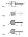
- the operator By looking at the section, the operator immediately sees if the rod is present over the entire axial length of the hole. If this is not the case, the plane of the section is not perpendicular to the axis of repetition of the sample. An error has been made. A new sample must be prepared.
- the template has a cylindrical head, of diameter greater than that of the rod and of the same longitudinal axis as the latter. This time, the operator sees in the section not only the stem but also the cut of the head. If the cope is trapezoidal, instead of being rectangular, the sample was not prepared correctly for the same reason as above. If the width, i.e. the dimension which is perpendicular to the axis of the rod, of the head section is less than the original diameter of the head, the section plane is parallel to what 'he should be. Another sample must be prepared.
- the template has a head, at least the end section of which is distant from the rod is conical.
- the control no longer requires a comparison of the dimensions of the head cope, but simply of its shape.
- the section plane is not the right one, if the angle at the top of the cone does not appear there.
- the lost template permanently coated and abraded at the same time as the sample, thus allows control of operations.
- the invention also relates to a method consisting in placing the wafer in a mold having a repetition axis so that the drilling axis is horizontal, in filling the mold with a coating resin, in hardening the resin. to obtain a coated sample and to abrade the coated sample to the plane perpendicular to the repetition axis passing through a diameter of the bore, characterized in that it consists, before putting the wafer in the mold, to thread remains in the bore the rod of a template, consisting of the rod, of diameter just less than the diameter of the bore, and of a head of the same axis as the rod and of diameter larger than the latter.
- the templates are advantageously made of brass or aluminum dyed in the mass with different colors according to the diameters of the rods. Templates adapted to different holes are thus easier to recognize.
- the coating resin is a transparent resin, in particular a methacrylic resin.
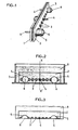
- each plate has eleven holes 3, the lower wall of which is coated with a metallic coating.
- Each template consists of a rod 4 with a diameter just smaller than that of a bore 3, once coated with a correct thickness of metal coating.
- the rod is extended by a head comprising a cylindrical part 5 of diameter significantly greater than that of the bore and ends in a conical part 6.
- the sizes are identical.
- the radius of the cylindrical parts 5 is greater than the distance between the center of the holes and the edge of the insert, the inserts 1 and 2 are held in a perfectly vertical manner by the templates. If one of the templates cannot penetrate a hole, the plate must be discarded. If the clearance is too large between the rod 4 and the diameter of a bore 3, to the point that the plate can tilt relative to the vertical, the plate must be discarded.
- the second stage of the process consists in placing the assembly produced in accordance with FIG. 1 on the bottom of a horizontal mold 7.
- the mold has a repetition axis X, X ', in particular an axis of revolution.
- the mold is filled with a coating resin 8 which may or may not be transparent. The resin is cured to obtain a coated sample. We take the sample out of the mold.
- the last stage of the process according to the invention consists in abrading the coated sample to the plane perpendicular to the repetition axis X, X ′ passing through a diameter of the bore. This gives the sample shown in Figure 3 which can be examined under a microscope.
Landscapes
- General Health & Medical Sciences (AREA)
- General Physics & Mathematics (AREA)
- Life Sciences & Earth Sciences (AREA)
- Chemical & Material Sciences (AREA)
- Analytical Chemistry (AREA)
- Biochemistry (AREA)
- Health & Medical Sciences (AREA)
- Immunology (AREA)
- Physics & Mathematics (AREA)
- Pathology (AREA)
- Sampling And Sample Adjustment (AREA)
- Analysing Materials By The Use Of Radiation (AREA)
- Medicinal Preparation (AREA)
- Solid-Sorbent Or Filter-Aiding Compositions (AREA)
- Separation Using Semi-Permeable Membranes (AREA)
Claims (9)
Priority Applications (1)
| Application Number | Priority Date | Filing Date | Title |
|---|---|---|---|
| AT87402284T ATE58597T1 (de) | 1986-12-05 | 1987-10-13 | Probe mit beschichteten bohrungen und methode zu ihrer herstellung. |
Applications Claiming Priority (2)
| Application Number | Priority Date | Filing Date | Title |
|---|---|---|---|
| FR8617062A FR2607928B1 (fr) | 1986-12-05 | 1986-12-05 | Echantillon a percage muni d'un revetement destine a etre examine au microscope et son procede de preparation |
| FR8617062 | 1986-12-05 |
Publications (2)
| Publication Number | Publication Date |
|---|---|
| EP0280822A1 EP0280822A1 (de) | 1988-09-07 |
| EP0280822B1 true EP0280822B1 (de) | 1990-11-22 |
Family
ID=9341620
Family Applications (1)
| Application Number | Title | Priority Date | Filing Date |
|---|---|---|---|
| EP87402284A Expired - Lifetime EP0280822B1 (de) | 1986-12-05 | 1987-10-13 | Probe mit beschichteten Bohrungen und Methode zu ihrer Herstellung |
Country Status (8)
| Country | Link |
|---|---|
| US (1) | US4833913A (de) |
| EP (1) | EP0280822B1 (de) |
| JP (1) | JPS63149538A (de) |
| AT (1) | ATE58597T1 (de) |
| DE (1) | DE3766361D1 (de) |
| DK (1) | DK165074C (de) |
| ES (1) | ES2018563B3 (de) |
| FR (1) | FR2607928B1 (de) |
Families Citing this family (1)
| Publication number | Priority date | Publication date | Assignee | Title |
|---|---|---|---|---|
| CN110774351B (zh) * | 2019-09-24 | 2021-10-12 | 惠州市金百泽电路科技有限公司 | 一种厚型无内定位光模多模组件连接器的加工方法 |
Family Cites Families (3)
| Publication number | Priority date | Publication date | Assignee | Title |
|---|---|---|---|---|
| US2494834A (en) * | 1945-07-10 | 1950-01-17 | Richard S Ringheim | Mounted specimen |
| US2776596A (en) * | 1952-07-28 | 1957-01-08 | Eigen Morris | Preparation and mounting of specimen sections |
| JPS5335163A (en) * | 1976-09-14 | 1978-04-01 | Hitachi Chemical Co Ltd | Method of producing printed circuit board substrate having through hole from metallic material |
-
1986
- 1986-12-05 FR FR8617062A patent/FR2607928B1/fr not_active Expired
-
1987
- 1987-10-13 ES ES87402284T patent/ES2018563B3/es not_active Expired - Lifetime
- 1987-10-13 DE DE8787402284T patent/DE3766361D1/de not_active Expired - Fee Related
- 1987-10-13 AT AT87402284T patent/ATE58597T1/de not_active IP Right Cessation
- 1987-10-13 EP EP87402284A patent/EP0280822B1/de not_active Expired - Lifetime
- 1987-11-16 US US07/120,850 patent/US4833913A/en not_active Expired - Fee Related
- 1987-12-02 DK DK632887A patent/DK165074C/da not_active IP Right Cessation
- 1987-12-02 JP JP62303461A patent/JPS63149538A/ja active Pending
Non-Patent Citations (1)
| Title |
|---|
| Revue Structure 10, Struers Nouveautés Métallographiques d'avril 1985, fig. 4 (version française) * |
Also Published As
| Publication number | Publication date |
|---|---|
| EP0280822A1 (de) | 1988-09-07 |
| DK632887D0 (da) | 1987-12-02 |
| ATE58597T1 (de) | 1990-12-15 |
| FR2607928A1 (fr) | 1988-06-10 |
| JPS63149538A (ja) | 1988-06-22 |
| DE3766361D1 (de) | 1991-01-03 |
| FR2607928B1 (fr) | 1989-02-17 |
| ES2018563B3 (es) | 1991-04-16 |
| DK165074B (da) | 1992-10-05 |
| US4833913A (en) | 1989-05-30 |
| DK632887A (da) | 1988-06-06 |
| DK165074C (da) | 1993-02-15 |
Similar Documents
| Publication | Publication Date | Title |
|---|---|---|
| EP2282877B1 (de) | Verfahren zur herstellung eines teils mit einem hohlkörper aus einem verbundmaterial und danach hergestelltes teil | |
| FR2493205A1 (fr) | Procede de fabrication d'un objet creux | |
| EP0156747A1 (de) | Verfahren und Vorrichtung zum Ausschneiden von quadratischen oder rechteckigen Öffnungen in Bilderrahmen | |
| EP0051510A1 (de) | Einrichtung für die optische Fasereinstellung in einer aus einem Stück gebildeten Zwinge zum Verbinden von zwei Transmissionskabeln mittels optischer Fasern | |
| EP1986003A1 (de) | Verfahren und Anlage zur nicht-destruktiven Kontrolle mit Hilfe von Wirbelströmen mit automatischer Eichung | |
| EP0021902A1 (de) | Verfahren zur Befestigung von Isolierstangen in Aufhängungsarmaturen und Vorrichtung zu dessen Ausführung | |
| EP0280822A1 (de) | Probe mit beschichteten Bohrungen und Methode zu ihrer Herstellung | |
| FR2788234A1 (fr) | Procede de chanfreinage | |
| CH646045A5 (fr) | Manche pour instrument dentaire a canaux, rotatif, et procede de fabrication d'un tel manche. | |
| CA2932995A1 (fr) | Table de coupe pour la decoupe d'une preforme fibreuse obtenue par tissage tridimensionnel et procede de decoupe utilisant une telle table | |
| EP0151542A1 (de) | Verfahren und Vorrichtung, um die Öffnung eines strukturellen Flugzeugrahmens provisorisch zu vergrössern | |
| FR2688590A1 (fr) | Eprouvette de traction/compression triaxiale. | |
| EP0262998B1 (de) | Bohrvorrichtung für Holzpaneele und ihr Zusammenbau durch Dübeln | |
| FR2624605A1 (fr) | Appareil pour l'execution d'essais de flexion a quatre points d'appui | |
| EP3590843B1 (de) | Herstellungsverfahren eines schalldämmpaneels mit einsätzen | |
| EP0197229A1 (de) | Auf einen Autokarosserieprüfstand zu montierende Vorrichtung zur lokalisierten Kontrolle und eventuellen Wiederinstandsetzung | |
| FR3121372A1 (fr) | Système d’insertion de tiges dans une ébauche de noyau céramique pour la fabrication d’aubes de turbomachine | |
| EP4028201B1 (de) | Werkzeug zum halten einer schaufel während des reibschweissens derselben an einem rotorelement einer turbomaschine eines flugzeuges | |
| EP0657903A1 (de) | Verfahren zum Wickeln eines Kerns mit einem elektronsichen Bauelement, sowie Mittel zur Führung von Drähten zum Verbinden einer Spule mit dem elektronischen Bauelement | |
| FR2785727A1 (fr) | Connecteur a contacts recentres | |
| EP0995547B1 (de) | Verfahren zum Bestimmen von einer Nut für eine Brillenglaslinse | |
| FR3117915A1 (fr) | Procédé de découpe et de récupération de bâtonnet en cellule blindée | |
| FR3117914A1 (fr) | Moule pour fabrication de bâtonnets en cellule blindée. | |
| CH623425A5 (en) | Process for the manufacture of a cluster guide for a nuclear reactor and tools for making use of this process | |
| EP0915260A1 (de) | Befestigungsverfahren für ein Führungsglied auf einem Träger, nach diesem Verfahren hergestellte Führungseinrichtung und Markierungsgerät mit einer solchen Vorrichtung |
Legal Events
| Date | Code | Title | Description |
|---|---|---|---|
| PUAI | Public reference made under article 153(3) epc to a published international application that has entered the european phase |
Free format text: ORIGINAL CODE: 0009012 |
|
| AK | Designated contracting states |
Kind code of ref document: A1 Designated state(s): AT BE CH DE ES GB GR IT LI LU NL SE |
|
| 17P | Request for examination filed |
Effective date: 19890209 |
|
| 17Q | First examination report despatched |
Effective date: 19900118 |
|
| GRAA | (expected) grant |
Free format text: ORIGINAL CODE: 0009210 |
|
| ITF | It: translation for a ep patent filed | ||
| AK | Designated contracting states |
Kind code of ref document: B1 Designated state(s): AT BE CH DE ES GB GR IT LI LU NL SE |
|
| PG25 | Lapsed in a contracting state [announced via postgrant information from national office to epo] |
Ref country code: GR Free format text: LAPSE BECAUSE OF FAILURE TO SUBMIT A TRANSLATION OF THE DESCRIPTION OR TO PAY THE FEE WITHIN THE PRESCRIBED TIME-LIMIT Effective date: 19901122 |
|
| REF | Corresponds to: |
Ref document number: 58597 Country of ref document: AT Date of ref document: 19901215 Kind code of ref document: T |
|
| GBT | Gb: translation of ep patent filed (gb section 77(6)(a)/1977) | ||
| REF | Corresponds to: |
Ref document number: 3766361 Country of ref document: DE Date of ref document: 19910103 |
|
| PLBE | No opposition filed within time limit |
Free format text: ORIGINAL CODE: 0009261 |
|
| STAA | Information on the status of an ep patent application or granted ep patent |
Free format text: STATUS: NO OPPOSITION FILED WITHIN TIME LIMIT |
|
| 26N | No opposition filed | ||
| ITTA | It: last paid annual fee | ||
| PGFP | Annual fee paid to national office [announced via postgrant information from national office to epo] |
Ref country code: LU Payment date: 19931001 Year of fee payment: 7 |
|
| PGFP | Annual fee paid to national office [announced via postgrant information from national office to epo] |
Ref country code: SE Payment date: 19931012 Year of fee payment: 7 |
|
| PGFP | Annual fee paid to national office [announced via postgrant information from national office to epo] |
Ref country code: CH Payment date: 19931018 Year of fee payment: 7 Ref country code: AT Payment date: 19931018 Year of fee payment: 7 |
|
| PGFP | Annual fee paid to national office [announced via postgrant information from national office to epo] |
Ref country code: ES Payment date: 19931025 Year of fee payment: 7 |
|
| PGFP | Annual fee paid to national office [announced via postgrant information from national office to epo] |
Ref country code: BE Payment date: 19931029 Year of fee payment: 7 |
|
| PGFP | Annual fee paid to national office [announced via postgrant information from national office to epo] |
Ref country code: NL Payment date: 19931031 Year of fee payment: 7 |
|
| EPTA | Lu: last paid annual fee | ||
| PGFP | Annual fee paid to national office [announced via postgrant information from national office to epo] |
Ref country code: DE Payment date: 19941011 Year of fee payment: 8 |
|
| PG25 | Lapsed in a contracting state [announced via postgrant information from national office to epo] |
Ref country code: LU Free format text: LAPSE BECAUSE OF NON-PAYMENT OF DUE FEES Effective date: 19941013 Ref country code: AT Effective date: 19941013 |
|
| PG25 | Lapsed in a contracting state [announced via postgrant information from national office to epo] |
Ref country code: SE Effective date: 19941014 Ref country code: ES Free format text: LAPSE BECAUSE OF EXPIRATION OF PROTECTION Effective date: 19941014 |
|
| PGFP | Annual fee paid to national office [announced via postgrant information from national office to epo] |
Ref country code: GB Payment date: 19941026 Year of fee payment: 8 |
|
| PG25 | Lapsed in a contracting state [announced via postgrant information from national office to epo] |
Ref country code: LI Effective date: 19941031 Ref country code: CH Effective date: 19941031 Ref country code: BE Effective date: 19941031 |
|
| EAL | Se: european patent in force in sweden |
Ref document number: 87402284.1 |
|
| BERE | Be: lapsed |
Owner name: S.A. HYPREZ Effective date: 19941031 |
|
| PG25 | Lapsed in a contracting state [announced via postgrant information from national office to epo] |
Ref country code: NL Effective date: 19950501 |
|
| NLV4 | Nl: lapsed or anulled due to non-payment of the annual fee | ||
| REG | Reference to a national code |
Ref country code: CH Ref legal event code: PL |
|
| EUG | Se: european patent has lapsed |
Ref document number: 87402284.1 |
|
| PG25 | Lapsed in a contracting state [announced via postgrant information from national office to epo] |
Ref country code: GB Effective date: 19951013 |
|
| GBPC | Gb: european patent ceased through non-payment of renewal fee |
Effective date: 19951013 |
|
| PG25 | Lapsed in a contracting state [announced via postgrant information from national office to epo] |
Ref country code: DE Effective date: 19960702 |
|
| REG | Reference to a national code |
Ref country code: ES Ref legal event code: FD2A Effective date: 19990601 |
|
| PG25 | Lapsed in a contracting state [announced via postgrant information from national office to epo] |
Ref country code: IT Free format text: LAPSE BECAUSE OF NON-PAYMENT OF DUE FEES;WARNING: LAPSES OF ITALIAN PATENTS WITH EFFECTIVE DATE BEFORE 2007 MAY HAVE OCCURRED AT ANY TIME BEFORE 2007. THE CORRECT EFFECTIVE DATE MAY BE DIFFERENT FROM THE ONE RECORDED. Effective date: 20051013 |