EP0280686B1 - Plattenwärmeaustauscher - Google Patents
Plattenwärmeaustauscher Download PDFInfo
- Publication number
- EP0280686B1 EP0280686B1 EP87900702A EP87900702A EP0280686B1 EP 0280686 B1 EP0280686 B1 EP 0280686B1 EP 87900702 A EP87900702 A EP 87900702A EP 87900702 A EP87900702 A EP 87900702A EP 0280686 B1 EP0280686 B1 EP 0280686B1
- Authority
- EP
- European Patent Office
- Prior art keywords
- plate
- heat exchange
- ring gasket
- lining
- port
- Prior art date
- Legal status (The legal status is an assumption and is not a legal conclusion. Google has not performed a legal analysis and makes no representation as to the accuracy of the status listed.)
- Expired
Links
- 238000007789 sealing Methods 0.000 claims abstract description 11
- 238000003754 machining Methods 0.000 claims abstract description 7
- 238000000926 separation method Methods 0.000 claims description 28
- 239000007769 metal material Substances 0.000 claims description 16
- 230000000284 resting effect Effects 0.000 claims 2
- 230000002452 interceptive effect Effects 0.000 abstract 1
- 229920001971 elastomer Polymers 0.000 description 18
- 239000002184 metal Substances 0.000 description 6
- 229910052751 metal Inorganic materials 0.000 description 6
- 238000000034 method Methods 0.000 description 3
- RTAQQCXQSZGOHL-UHFFFAOYSA-N Titanium Chemical compound [Ti] RTAQQCXQSZGOHL-UHFFFAOYSA-N 0.000 description 1
- 238000004026 adhesive bonding Methods 0.000 description 1
- 239000002131 composite material Substances 0.000 description 1
- 238000005260 corrosion Methods 0.000 description 1
- 230000007797 corrosion Effects 0.000 description 1
- 239000000806 elastomer Substances 0.000 description 1
- 229910000856 hastalloy Inorganic materials 0.000 description 1
- 239000000463 material Substances 0.000 description 1
- 150000002739 metals Chemical class 0.000 description 1
- 239000004033 plastic Substances 0.000 description 1
- 229910001220 stainless steel Inorganic materials 0.000 description 1
- 239000010935 stainless steel Substances 0.000 description 1
- 239000010936 titanium Substances 0.000 description 1
- 229910052719 titanium Inorganic materials 0.000 description 1
- 238000003466 welding Methods 0.000 description 1
Images


Classifications
-
- F—MECHANICAL ENGINEERING; LIGHTING; HEATING; WEAPONS; BLASTING
- F28—HEAT EXCHANGE IN GENERAL
- F28F—DETAILS OF HEAT-EXCHANGE AND HEAT-TRANSFER APPARATUS, OF GENERAL APPLICATION
- F28F3/00—Plate-like or laminated elements; Assemblies of plate-like or laminated elements
- F28F3/08—Elements constructed for building-up into stacks, e.g. capable of being taken apart for cleaning
- F28F3/083—Elements constructed for building-up into stacks, e.g. capable of being taken apart for cleaning capable of being taken apart
-
- Y—GENERAL TAGGING OF NEW TECHNOLOGICAL DEVELOPMENTS; GENERAL TAGGING OF CROSS-SECTIONAL TECHNOLOGIES SPANNING OVER SEVERAL SECTIONS OF THE IPC; TECHNICAL SUBJECTS COVERED BY FORMER USPC CROSS-REFERENCE ART COLLECTIONS [XRACs] AND DIGESTS
- Y10—TECHNICAL SUBJECTS COVERED BY FORMER USPC
- Y10S—TECHNICAL SUBJECTS COVERED BY FORMER USPC CROSS-REFERENCE ART COLLECTIONS [XRACs] AND DIGESTS
- Y10S165/00—Heat exchange
- Y10S165/355—Heat exchange having separate flow passage for two distinct fluids
- Y10S165/356—Plural plates forming a stack providing flow passages therein
Definitions
- This invention relates to a plate heat exchanger comprising a group of heat exchange plates mounted between two end plates, ports for intake and outflow of the exchange media provided in one or both end plates, the ports being fitted with linings, and the heat exchange plates having ports in alignment with the intake and outflow ports and being provided around these ports with ring gasket receiving grooves, in their front sides.
- a conventional plate heat exchanger comprises two end plates, namely a frame plate, and a pressure plate, and between these end plates several heat exchange plates, all of which plates are mounted in a frame.
- the heat exchange plates and, at least one of the frame plate and the pressure plate are provided with openings at their corner regions which openings function as ports for intake and outflow of the heat exchange media.
- the ports in the end plates are commonly provided with special linings resistantto corrosive media.
- a separation plate is provided between the frame plate and the pressure plate, a respective group of heat exchange plates being provided on either side of the separation plate which is also provided with ports for the heat exchange media. Similar problems arise in plate heat exchangers incorporating separation plates.
- end plate is used herein to denote a frame plate, a pressure plate or a separation plate.
- a plate heat exchanger comprising a group of heat exchange plates interposed between two end plates the plates of the group having front sides facing one end plate and rear sides facing the other end plate, ports for intake and outflow of heat exchange media provided in at least one end plate, each of at least some of said ports being fitting with a lining so formed that machining of the side faces of the end plate around the port is not required to accommodate the lining, and the heat exchange plates having ports aligned with said intake and outflow ports and having in their front faces ring gasket receiving grooves, characterised in that said other end plate has ports fitted with said linings and at each said port the first heat exchange plate adjacentto said other end plate is sealed to the next heat exchange plate by a ring gasket means engaging the front side of said first adjacent heat exchange plate and sealed directly to said lining.
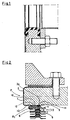
- FIG. 2 there is shown an end plate, namely a frame plate or a pressure plate 1 provided with a metal lining 2 in one of its ports.
- each heat exchange plate 3 has a ring gasket groove 4 accommodating a ring gasket 5 and having a rear side 9 which is accordingly directed towards the frame or pressure plate 1.
- Each ring gasket groove 4 has a cross-section comprising two oblique flanks 6, 7 and an intermediate plane portion 8.
- the first heat exchange plate closest to the end plate 1 would rest with the rear side 9 of the ring gasket groove against the one flange 2a of the metal lining 2 and the seal obtained between the heat exchange plate and the metal lining would not be sufficient.
- an annular portion of the first heat exchange plate closest to the end plate 1 is cut away around the port in the heat exchange plate.
- the radial width of the severed portion is such that the inner one 6 of the flanks of the ring gasket groove is removed.
- the severed portion is replaced by an annular elastic gasket 10, preferably made of rubber.
- the gasket 10 comprises a plane portion 11 intended to rest against and be fastened e.g.
- the gasket 10 comprises an additional plane portion 12 radially inside the plane portion 11, and provided with a projection 13 which serves to form the main seal between the end plate and the first heat exchange plate.
- the plane portion 12 lies on a level axially closer to the end plate 1 than the level of the plane portion 11.
- the gasket portion 12 can be provided with an annular plate R 1 which partly encloses this portion and helps to equalise the load from the adjacent heat exchange plate.
- Fig. 3 there is shown an end plate, namely a frame or pressure plate 1 provided with a rubber lining 14 in one of its ports.
- One 15 of the flanges of the lining functions as a gasket between the two heat exchange plates closest to the end plate 1, and also serves as a gasket sealing between the end plate and the first heat exchange plate.
- the first heat exchange plate is machined around its port in the same way as the corresponding heat exchange plate in the embodiment according to Fig. 2.
- a recess is provided in the rubber flange 15 to receive the portion 8 of the heat exchange plate 3.
- the outer portion of the rubber flange 15 rests against the plane portion 8 of the ring gasket groove on the side of the plate remote from the end plate, and the end surface of the rubber flange extends essentially up to the oblique flank 7 of the ring gasket groove 4, with the result that the outer portion of the rubber flange functions as a ring gasket between the two heat exchange plates closest to the frame or pressure plate 1.
- the rubber flange 15 as is shown in the Figure, can be provided with an annular plate R 2 extending radially outwardly from the port and having the same function as the above-mentioned plate R 1 .
- Figures 4 and 5 disclose embodiments very similar to that of Fig. 2. The difference is that a composite lining made of metallic and non-metallic materials is used. Thus, in Fig. 4 at least that flange 2a of the lining which rests against the first heat exchange plate 3 is made of the metallic material. The seal between this flange 2a and the heat exchange plate is achieved in the same way as in the embodiment according to Fig. 2.
- the flange 2a of the lining comprises a metallic portion 50 and a non-metallic portion 51, which latter portion is an integral part of the remaining part of the lining, preferably made of rubber.
- the metallic portion 50 rests against the frame plate or the pressure plate 1 while the non-metallic portion 51 is on the outside of the metallic portion and, accordingly, is in contact with the gasket 10 and the heat exchange plate 3.
- a fifth embodiment of the invention the lining 22 of a frame plate or pressure plate 1 comprises an elastic part having a flange 16 and a cylindrical portion 17.
- the flange 16 is provided with a shoulder 18 intended to rest against a flange of a connecting tube (not shown).
- the elastic part of the lining cooperates with a metallic part comprising a cylindrical portion 19 and a flange 20.
- This flange 20 is made in one piece with a ring gasket 21 intended to be applied into the ring gasket groove of the heat exchange plate lying closest to the frame plate or the pressure plate.
- this ring gasket 21 integral with the lining functions as a gasket between the two heat exchange plates closest to the frame plate or pressure plate.
- the heat exchange plate closest to the frame plate or pressure plate rests directly against the said plate but this does not matter because no direct sealing between the frame plate or pressure plate and the adjacent heat exchange plate is needed since the lining extends axially to the level between the first and second heat exchange plates nearest to the frame plate or pressure plate.
- the embodiment according to Fig. 7 differs from that according to Fig. 6 only in that the whole lining 23 is made of a metallic material.
- the lining is made from two parts, the two cylindrical portions of the lining parts being fastened to each other in a suitable way, for instance by welding.
- the flange 20 is fixedly attached to the ring gasket 21.
- the flange 20 has such a design that it rests against the plate 3 in such a way that it follows the contour of the ring gasket groove 4 of the heat exchange plate 3 over one side flank and the groove bottom.
- a ring gasket 21 is placed between the two adjacent heat exchange plates, whereby these two plates are sealed to each other.
- An advantage with this embodiment is that if the ring gasket 21 needs to be replaced it is simply a matter of removing the old gasketand inserting a newone.
- Fig. 9 there is shown an embodiment different from that according to Fig. 6 only in thatthe whole lining 90 is made of a non-metallic material, preferably rubber.
- the elastic, non-metallic material can be rubber.
- the invention is, of course, not limited to rubber; other elastomers such as plastic materials can be used.
- the metallic material can be stainless steel, titanium, hastalloy or other metals.
- a separation plate is sometimes used for changing the flow of the medium.
- the separation plate is located inside the plate package which makes it possible for the media to pass through the separation plate. Therefore, there are the same demands regarding the corrosion resistance upon the connection ports of the separation plate as applied to the connection ports of the frame plate and the pressure plate. Thus, the separation plate previously had to be machined if linings were inserted into the ports of the same separation plate.
- FIG. 10 there is shown an end plate consisting of a separation plate 100 located between two groups of heat exchange plates and provided with a lining 101 of a non-metallic material for protecting the plate at a port P.
- the heat exchange plates 102 on the right side of the separation plate having the ring gasket receiving grooves directed from the separation plate while the plates on the left side of the separation plate have the gasket receiving grooves directed towards the separation plate.
- the lining 101 made of an elastic, non-metallic material, preferably rubber, has two flanges 103, 104.
- the flange 104 on the right side of the separation plate cooperates with the heat exchange plates in the same way as is shown in Fig. 3 while the flange 103 on the left side of the separation plate is provided with an integral ring gasket 105 intended to fit in the ring gasket groove of the adjacent heat exchange plate in the same way as is shown in WO 84/01209.
- a separation plate 110 provided with a lining 111 of metallic material for lining of the port P.
- the metal lining comprises two flanges 112,113,the flange 113 on the right side of the separation plate co-operating with the adjacent heat exchange plate via a ring gasket 114 in the same way as is shown in Figs. 2 and 4, and the flange 112 on the left side of the separation plate co-operating with the adjacent heat exchange plate via a ring gasket 115 located in its ring gasket groove.
- Figs. 2-9 can be applied to a separation plate.
- Fig. 12 there is shown a lining applied onto a frame plate or pressure plate facing the gasket grooves of the heat exchange plates.
- the figure shows a frame plate or pressure plate 120 provided with a rubber lining 121 at one of its ports.
- One flange 122 functions as a gasket between the frame plate or pressure plate 120 and the adjacent heat exchange plate 123.
- the heat exchange plate has a ring gasket groove with a cross-section comprising two flanks 124,125 and an intermediate plane portion 126. In orderthatthe necessary seals are obtained the first heat exchange plate must be machined in a particular way.
- an annular part of the heat exchange plate is cut away around the port, the portion removed including the inner flank 124 of the ring gasket groove.
- the outer part of the rubber flange 122 rests against the plane portion 126 of the ring gasket groove of thefirst plate 123, the end surface of therubber flange 122 extending essentially up to the oblique flank 125 of the ring gasket groove, with the result that the rubber flange 122 functions as a ring gasket between the frame plate or pressure plate 120 and the adjacent heat exchange plate 123.
- the lining 121 in Fig. 12 of one metallic part and one non-metallic part, that part of the lining which co-operates with the heat exchange plate, being of non-metallic material.
Landscapes
- Engineering & Computer Science (AREA)
- Physics & Mathematics (AREA)
- Thermal Sciences (AREA)
- Mechanical Engineering (AREA)
- General Engineering & Computer Science (AREA)
- Heat-Exchange Devices With Radiators And Conduit Assemblies (AREA)
Claims (9)
Applications Claiming Priority (2)
| Application Number | Priority Date | Filing Date | Title |
|---|---|---|---|
| SE8600127 | 1986-01-13 | ||
| SE8600127A SE8600127D0 (sv) | 1986-01-13 | 1986-01-13 | Anordning vid plattvermevexlare |
Publications (2)
| Publication Number | Publication Date |
|---|---|
| EP0280686A1 EP0280686A1 (de) | 1988-09-07 |
| EP0280686B1 true EP0280686B1 (de) | 1990-04-11 |
Family
ID=20363078
Family Applications (1)
| Application Number | Title | Priority Date | Filing Date |
|---|---|---|---|
| EP87900702A Expired EP0280686B1 (de) | 1986-01-13 | 1987-01-09 | Plattenwärmeaustauscher |
Country Status (5)
| Country | Link |
|---|---|
| US (1) | US4848451A (de) |
| EP (1) | EP0280686B1 (de) |
| JP (1) | JPH0697159B2 (de) |
| SE (1) | SE8600127D0 (de) |
| WO (1) | WO1987004234A1 (de) |
Families Citing this family (18)
| Publication number | Priority date | Publication date | Assignee | Title |
|---|---|---|---|---|
| US5494301A (en) * | 1993-04-20 | 1996-02-27 | W. L. Gore & Associates, Inc. | Wrapped composite gasket material |
| US6186223B1 (en) | 1998-08-27 | 2001-02-13 | Zeks Air Drier Corporation | Corrugated folded plate heat exchanger |
| US6244333B1 (en) | 1998-08-27 | 2001-06-12 | Zeks Air Drier Corporation | Corrugated folded plate heat exchanger |
| DE10035776C1 (de) * | 2000-07-22 | 2001-12-13 | Gea Ecoflex Gmbh | Plattenwärmetauscher |
| SE518971C2 (sv) * | 2001-04-24 | 2002-12-10 | Alfa Laval Ab | Foderanordning för en plattvärmeväxlare, plattvärmeväxlare och förfarande för tillverkning av en dylik |
| US6953598B2 (en) * | 2001-12-28 | 2005-10-11 | Wm. Wrigley Jr. Company | Dairy-based candy production utilizing plate and frame assembly |
| US9930898B2 (en) * | 2009-07-29 | 2018-04-03 | Tokitae Llc | Pasteurization system and method |
| US9599407B2 (en) * | 2009-07-29 | 2017-03-21 | Tokitae Llc | System and structure for heating or sterilizing a liquid stream |
| DE102010046864A1 (de) * | 2010-09-29 | 2012-03-29 | Gea Ecoflex Gmbh | Plattenwärmetauscher mit einem vollverschweißten Plattenpaket |
| JP5090515B2 (ja) * | 2010-11-29 | 2012-12-05 | 株式会社タクボ精機製作所 | 熱交換器 |
| US20140196870A1 (en) * | 2013-01-17 | 2014-07-17 | Hamilton Sundstrand Corporation | Plate heat exchanger |
| JP5722394B2 (ja) | 2013-07-11 | 2015-05-20 | 株式会社タクボ精機製作所 | 熱交換器 |
| US20170089644A1 (en) * | 2015-09-30 | 2017-03-30 | Spx Flow, Inc. | Port Connection for a Heat Exchanger |
| EP3182048A1 (de) | 2015-12-16 | 2017-06-21 | Alfa Laval Corporate AB | Lukendichtung, anordnung für einen wärmetauscher und wärmetauscher mit solch einer anordnung |
| US20180103655A1 (en) * | 2016-10-18 | 2018-04-19 | Ferrara Candy Company | Hard Candy with Gummy Center and Systems and Methods for Making Same |
| EP3333527A1 (de) * | 2016-12-08 | 2018-06-13 | Alfa Laval Corporate AB | Auskleidungsvorrichtung und wärmetauscher |
| PL3457066T3 (pl) * | 2017-09-15 | 2022-08-16 | Alfa Laval Corporate Ab | Przegroda |
| JP7100074B2 (ja) * | 2020-01-24 | 2022-07-12 | 株式会社日阪製作所 | プレート式熱交換器 |
Family Cites Families (11)
| Publication number | Priority date | Publication date | Assignee | Title |
|---|---|---|---|---|
| US2203123A (en) * | 1938-08-16 | 1940-06-04 | Astle William | Gasketed plate |
| GB1041805A (en) * | 1964-07-13 | 1966-09-07 | Apv Co Ltd | Improvements in or relating to plate heat exchanger connections |
| DE2007033C3 (de) * | 1970-02-17 | 1979-06-21 | Hoechst Ag, 6000 Frankfurt | Plattenwärmetauscher aus Polytetrafluorethylen |
| DE2112168A1 (de) * | 1970-03-20 | 1971-10-28 | Serck Industries Ltd | Plattenwaermeaustauscher |
| DE2357059C3 (de) * | 1973-11-15 | 1979-05-17 | Eduard Ahlborn Gmbh, 3200 Hildesheim | Abdichtung für einen Plattenwärmetauscher |
| GB2000267A (en) * | 1977-04-19 | 1979-01-04 | Apv Co Ltd | Immprovements in or relating to connecting ports for plate heat exchangers |
| GB2092241B (en) * | 1981-01-30 | 1984-07-18 | Apv The Co Ltd | Gasket arrangement for plate heat exchanger |
| SE456856B (sv) * | 1982-06-18 | 1988-11-07 | Alfa Laval Thermal Ab | Plattvaermevaexlare och saett att infodra en anslutningsport i denna |
| SE8205231D0 (sv) * | 1982-09-14 | 1982-09-14 | Alfa Laval Ab | Foder |
| SE8301177D0 (sv) * | 1983-03-03 | 1983-03-03 | Alfa Laval Ab | Stativ- och/eller tryckplatta for plattvermevexlare |
| US4586562A (en) * | 1983-08-10 | 1986-05-06 | Eltech Systems Corporation | Plate and frame heat exchanger assembly with anodic protection |
-
1986
- 1986-01-13 SE SE8600127A patent/SE8600127D0/xx unknown
-
1987
- 1987-01-09 US US07/193,280 patent/US4848451A/en not_active Expired - Lifetime
- 1987-01-09 EP EP87900702A patent/EP0280686B1/de not_active Expired
- 1987-01-09 WO PCT/SE1987/000006 patent/WO1987004234A1/en not_active Ceased
- 1987-01-09 JP JP62500616A patent/JPH0697159B2/ja not_active Expired - Lifetime
Also Published As
| Publication number | Publication date |
|---|---|
| SE8600127D0 (sv) | 1986-01-13 |
| JPH0697159B2 (ja) | 1994-11-30 |
| JPS63502210A (ja) | 1988-08-25 |
| US4848451A (en) | 1989-07-18 |
| WO1987004234A1 (en) | 1987-07-16 |
| EP0280686A1 (de) | 1988-09-07 |
Similar Documents
| Publication | Publication Date | Title |
|---|---|---|
| EP0280686B1 (de) | Plattenwärmeaustauscher | |
| EP0038170B1 (de) | Gleitringdichtung mit verbesserter Dichtringverbindung | |
| US4482089A (en) | Method of lining a fluid connection opening in a frame plate of a plate heat exchanger | |
| CA2371952C (en) | J-shaped seam tapping plate with gasket groove for spin-on filter assemblies | |
| US4746130A (en) | Flat gasket-type seal for placement between machine parts including hydraulic control panels | |
| US5839643A (en) | Method of weld-recoulping front cover and pump shell of torque converter | |
| EP0195682A2 (de) | Dichtung | |
| EP0169843B1 (de) | Rahmenplatte und/oder druckplatte für einen plattenwärmetauscher | |
| GB2164738A (en) | Heat exchanger | |
| CA2374872C (en) | Wing tapping plate for spin-on filters | |
| EP0172189B1 (de) | Dichtungsring vom komposittyp | |
| EP1381819B1 (de) | Auskleidungsvorrichtung für einen plattenwärmetauscher | |
| US4595208A (en) | Lining of non-metallic material | |
| EP0247043B1 (de) | Beschichtung für eingangs- und auslassöffnungen eines platten wärmeaustauschers | |
| AU741413B2 (en) | Hydraulic machine, opening flange of hydraulic machine and method of production thereof | |
| EP1189669B1 (de) | Filtervorrichtung | |
| CA1235606A (en) | Pump construction | |
| JPS6242208Y2 (de) | ||
| JPH11173422A (ja) | 圧力流体の液封装置 | |
| GB2147987A (en) | Improvements to heat transfer apparatus and plates therefor | |
| JPH07251010A (ja) | フィルタ | |
| JPH06281383A (ja) | プレート式熱交換器 | |
| JPS61105362A (ja) | 変速機のオイルポンプ | |
| GB2202019A (en) | Flanged pipe couplings |
Legal Events
| Date | Code | Title | Description |
|---|---|---|---|
| PUAI | Public reference made under article 153(3) epc to a published international application that has entered the european phase |
Free format text: ORIGINAL CODE: 0009012 |
|
| 17P | Request for examination filed |
Effective date: 19880429 |
|
| AK | Designated contracting states |
Kind code of ref document: A1 Designated state(s): DE FR GB IT SE |
|
| 17Q | First examination report despatched |
Effective date: 19881031 |
|
| GRAA | (expected) grant |
Free format text: ORIGINAL CODE: 0009210 |
|
| AK | Designated contracting states |
Kind code of ref document: B1 Designated state(s): DE FR GB IT SE |
|
| ITF | It: translation for a ep patent filed | ||
| REF | Corresponds to: |
Ref document number: 3762290 Country of ref document: DE Date of ref document: 19900517 |
|
| ET | Fr: translation filed | ||
| ITTA | It: last paid annual fee | ||
| PLBE | No opposition filed within time limit |
Free format text: ORIGINAL CODE: 0009261 |
|
| STAA | Information on the status of an ep patent application or granted ep patent |
Free format text: STATUS: NO OPPOSITION FILED WITHIN TIME LIMIT |
|
| 26N | No opposition filed | ||
| EAL | Se: european patent in force in sweden |
Ref document number: 87900702.9 |
|
| REG | Reference to a national code |
Ref country code: GB Ref legal event code: IF02 |
|
| PGFP | Annual fee paid to national office [announced via postgrant information from national office to epo] |
Ref country code: GB Payment date: 20060104 Year of fee payment: 20 |
|
| PGFP | Annual fee paid to national office [announced via postgrant information from national office to epo] |
Ref country code: SE Payment date: 20060105 Year of fee payment: 20 Ref country code: DE Payment date: 20060105 Year of fee payment: 20 |
|
| PGFP | Annual fee paid to national office [announced via postgrant information from national office to epo] |
Ref country code: FR Payment date: 20060110 Year of fee payment: 20 |
|
| PGFP | Annual fee paid to national office [announced via postgrant information from national office to epo] |
Ref country code: IT Payment date: 20060131 Year of fee payment: 20 |
|
| PG25 | Lapsed in a contracting state [announced via postgrant information from national office to epo] |
Ref country code: GB Free format text: LAPSE BECAUSE OF EXPIRATION OF PROTECTION Effective date: 20070108 |
|
| REG | Reference to a national code |
Ref country code: GB Ref legal event code: PE20 |
|
| EUG | Se: european patent has lapsed |