EP0280671B1 - Verfahren zur Oberflächenmarkierung von Walzwerkswalzen - Google Patents
Verfahren zur Oberflächenmarkierung von Walzwerkswalzen Download PDFInfo
- Publication number
- EP0280671B1 EP0280671B1 EP88870022A EP88870022A EP0280671B1 EP 0280671 B1 EP0280671 B1 EP 0280671B1 EP 88870022 A EP88870022 A EP 88870022A EP 88870022 A EP88870022 A EP 88870022A EP 0280671 B1 EP0280671 B1 EP 0280671B1
- Authority
- EP
- European Patent Office
- Prior art keywords
- bead
- gas
- roll
- microcraters
- jet
- Prior art date
- Legal status (The legal status is an assumption and is not a legal conclusion. Google has not performed a legal analysis and makes no representation as to the accuracy of the status listed.)
- Expired - Lifetime
Links
Images


Classifications
-
- C—CHEMISTRY; METALLURGY
- C21—METALLURGY OF IRON
- C21D—MODIFYING THE PHYSICAL STRUCTURE OF FERROUS METALS; GENERAL DEVICES FOR HEAT TREATMENT OF FERROUS OR NON-FERROUS METALS OR ALLOYS; MAKING METAL MALLEABLE, e.g. BY DECARBURISATION OR TEMPERING
- C21D9/00—Heat treatment, e.g. annealing, hardening, quenching or tempering, adapted for particular articles; Furnaces therefor
- C21D9/38—Heat treatment, e.g. annealing, hardening, quenching or tempering, adapted for particular articles; Furnaces therefor for roll bodies
-
- B—PERFORMING OPERATIONS; TRANSPORTING
- B21—MECHANICAL METAL-WORKING WITHOUT ESSENTIALLY REMOVING MATERIAL; PUNCHING METAL
- B21B—ROLLING OF METAL
- B21B27/00—Rolls, roll alloys or roll fabrication; Lubricating, cooling or heating rolls while in use
- B21B27/005—Rolls with a roughened or textured surface; Methods for making same
-
- B—PERFORMING OPERATIONS; TRANSPORTING
- B23—MACHINE TOOLS; METAL-WORKING NOT OTHERWISE PROVIDED FOR
- B23K—SOLDERING OR UNSOLDERING; WELDING; CLADDING OR PLATING BY SOLDERING OR WELDING; CUTTING BY APPLYING HEAT LOCALLY, e.g. FLAME CUTTING; WORKING BY LASER BEAM
- B23K26/00—Working by laser beam, e.g. welding, cutting or boring
- B23K26/08—Devices involving relative movement between laser beam and workpiece
- B23K26/0823—Devices involving rotation of the workpiece
-
- B—PERFORMING OPERATIONS; TRANSPORTING
- B23—MACHINE TOOLS; METAL-WORKING NOT OTHERWISE PROVIDED FOR
- B23K—SOLDERING OR UNSOLDERING; WELDING; CLADDING OR PLATING BY SOLDERING OR WELDING; CUTTING BY APPLYING HEAT LOCALLY, e.g. FLAME CUTTING; WORKING BY LASER BEAM
- B23K26/00—Working by laser beam, e.g. welding, cutting or boring
- B23K26/12—Working by laser beam, e.g. welding, cutting or boring in a special atmosphere, e.g. in an enclosure
- B23K26/123—Working by laser beam, e.g. welding, cutting or boring in a special atmosphere, e.g. in an enclosure in an atmosphere of particular gases
-
- B—PERFORMING OPERATIONS; TRANSPORTING
- B23—MACHINE TOOLS; METAL-WORKING NOT OTHERWISE PROVIDED FOR
- B23K—SOLDERING OR UNSOLDERING; WELDING; CLADDING OR PLATING BY SOLDERING OR WELDING; CUTTING BY APPLYING HEAT LOCALLY, e.g. FLAME CUTTING; WORKING BY LASER BEAM
- B23K26/00—Working by laser beam, e.g. welding, cutting or boring
- B23K26/14—Working by laser beam, e.g. welding, cutting or boring using a fluid stream, e.g. a jet of gas, in conjunction with the laser beam; Nozzles therefor
- B23K26/142—Working by laser beam, e.g. welding, cutting or boring using a fluid stream, e.g. a jet of gas, in conjunction with the laser beam; Nozzles therefor for the removal of by-products
-
- B—PERFORMING OPERATIONS; TRANSPORTING
- B23—MACHINE TOOLS; METAL-WORKING NOT OTHERWISE PROVIDED FOR
- B23K—SOLDERING OR UNSOLDERING; WELDING; CLADDING OR PLATING BY SOLDERING OR WELDING; CUTTING BY APPLYING HEAT LOCALLY, e.g. FLAME CUTTING; WORKING BY LASER BEAM
- B23K26/00—Working by laser beam, e.g. welding, cutting or boring
- B23K26/14—Working by laser beam, e.g. welding, cutting or boring using a fluid stream, e.g. a jet of gas, in conjunction with the laser beam; Nozzles therefor
- B23K26/1435—Working by laser beam, e.g. welding, cutting or boring using a fluid stream, e.g. a jet of gas, in conjunction with the laser beam; Nozzles therefor involving specially adapted flow control means
- B23K26/1437—Working by laser beam, e.g. welding, cutting or boring using a fluid stream, e.g. a jet of gas, in conjunction with the laser beam; Nozzles therefor involving specially adapted flow control means for flow rate control
-
- B—PERFORMING OPERATIONS; TRANSPORTING
- B23—MACHINE TOOLS; METAL-WORKING NOT OTHERWISE PROVIDED FOR
- B23K—SOLDERING OR UNSOLDERING; WELDING; CLADDING OR PLATING BY SOLDERING OR WELDING; CUTTING BY APPLYING HEAT LOCALLY, e.g. FLAME CUTTING; WORKING BY LASER BEAM
- B23K26/00—Working by laser beam, e.g. welding, cutting or boring
- B23K26/14—Working by laser beam, e.g. welding, cutting or boring using a fluid stream, e.g. a jet of gas, in conjunction with the laser beam; Nozzles therefor
- B23K26/1435—Working by laser beam, e.g. welding, cutting or boring using a fluid stream, e.g. a jet of gas, in conjunction with the laser beam; Nozzles therefor involving specially adapted flow control means
- B23K26/1438—Working by laser beam, e.g. welding, cutting or boring using a fluid stream, e.g. a jet of gas, in conjunction with the laser beam; Nozzles therefor involving specially adapted flow control means for directional control
-
- B—PERFORMING OPERATIONS; TRANSPORTING
- B23—MACHINE TOOLS; METAL-WORKING NOT OTHERWISE PROVIDED FOR
- B23K—SOLDERING OR UNSOLDERING; WELDING; CLADDING OR PLATING BY SOLDERING OR WELDING; CUTTING BY APPLYING HEAT LOCALLY, e.g. FLAME CUTTING; WORKING BY LASER BEAM
- B23K26/00—Working by laser beam, e.g. welding, cutting or boring
- B23K26/352—Working by laser beam, e.g. welding, cutting or boring for surface treatment
- B23K26/355—Texturing
-
- B—PERFORMING OPERATIONS; TRANSPORTING
- B23—MACHINE TOOLS; METAL-WORKING NOT OTHERWISE PROVIDED FOR
- B23K—SOLDERING OR UNSOLDERING; WELDING; CLADDING OR PLATING BY SOLDERING OR WELDING; CUTTING BY APPLYING HEAT LOCALLY, e.g. FLAME CUTTING; WORKING BY LASER BEAM
- B23K26/00—Working by laser beam, e.g. welding, cutting or boring
- B23K26/352—Working by laser beam, e.g. welding, cutting or boring for surface treatment
- B23K26/3568—Modifying rugosity
- B23K26/3584—Increasing rugosity, e.g. roughening
-
- B—PERFORMING OPERATIONS; TRANSPORTING
- B44—DECORATIVE ARTS
- B44B—MACHINES, APPARATUS OR TOOLS FOR ARTISTIC WORK, e.g. FOR SCULPTURING, GUILLOCHING, CARVING, BRANDING, INLAYING
- B44B3/00—Artist's machines or apparatus equipped with tools or work holders moving or able to be controlled substantially two- dimensionally for carving, engraving, or guilloching shallow ornamenting or markings
- B44B3/04—Artist's machines or apparatus equipped with tools or work holders moving or able to be controlled substantially two- dimensionally for carving, engraving, or guilloching shallow ornamenting or markings wherein non-plane surfaces are worked
-
- B—PERFORMING OPERATIONS; TRANSPORTING
- B44—DECORATIVE ARTS
- B44B—MACHINES, APPARATUS OR TOOLS FOR ARTISTIC WORK, e.g. FOR SCULPTURING, GUILLOCHING, CARVING, BRANDING, INLAYING
- B44B7/00—Machines, apparatus or hand tools for branding, e.g. using radiant energy such as laser beams
-
- B—PERFORMING OPERATIONS; TRANSPORTING
- B21—MECHANICAL METAL-WORKING WITHOUT ESSENTIALLY REMOVING MATERIAL; PUNCHING METAL
- B21B—ROLLING OF METAL
- B21B2267/00—Roll parameters
- B21B2267/10—Roughness of roll surface
-
- B—PERFORMING OPERATIONS; TRANSPORTING
- B23—MACHINE TOOLS; METAL-WORKING NOT OTHERWISE PROVIDED FOR
- B23K—SOLDERING OR UNSOLDERING; WELDING; CLADDING OR PLATING BY SOLDERING OR WELDING; CUTTING BY APPLYING HEAT LOCALLY, e.g. FLAME CUTTING; WORKING BY LASER BEAM
- B23K2103/00—Materials to be soldered, welded or cut
- B23K2103/02—Iron or ferrous alloys
- B23K2103/04—Steel or steel alloys
-
- Y—GENERAL TAGGING OF NEW TECHNOLOGICAL DEVELOPMENTS; GENERAL TAGGING OF CROSS-SECTIONAL TECHNOLOGIES SPANNING OVER SEVERAL SECTIONS OF THE IPC; TECHNICAL SUBJECTS COVERED BY FORMER USPC CROSS-REFERENCE ART COLLECTIONS [XRACs] AND DIGESTS
- Y10—TECHNICAL SUBJECTS COVERED BY FORMER USPC
- Y10T—TECHNICAL SUBJECTS COVERED BY FORMER US CLASSIFICATION
- Y10T428/00—Stock material or miscellaneous articles
- Y10T428/12—All metal or with adjacent metals
- Y10T428/12993—Surface feature [e.g., rough, mirror]
Definitions
- the present invention relates to a method of marking the surface of a rolling mill cylinder, with the aim of giving this surface an isotropic and durable roughness.
- the invention also extends to a cylinder whose surface is marked by this method.
- a process in accordance with the preamble of claim 1 is known from the publication "Etching the roughness of rolling mill rolls by laser pulses", J. Crahay et al, Revue de Métallurgie-CIT, vol. 80, NO. 5, (May 1983), pp 393-401.
- This roughness of the cylinder consists of a multitude of valleys and microscopic peaks, which respectively print plateaus and valleys in the surface of the sheet.
- the regularity of the dimensions and the distribution of this roughness influences in particular the suitability of these sheets for stamping and coating.
- the rolling mill cylinder is rotated about its longitudinal axis and its surface is struck by a succession of laser pulses produced by chopping a continuous laser beam by means of an open-ended disc.
- the laser beam travels along the cylinder, so that its impact area follows a helical path on the surface of the cylinder.
- each laser pulse causes the heating of a certain volume of metal and, inside this volume, the fusion of a droplet of metal from the cylinder .
- the volume of heated metal, as well as that of the molten metal, depends on the power and the duration of the laser pulse.
- the action of the laser pulse is generally reinforced by a jet of oxidizing gas directed towards the aforementioned impact zone. The brutal local rise in temperature causes the formation of a plasma above the impact zone, by combustion of the metal.
- This plasma exerts a pressure on the molten metal which, combined with the mechanical effect of the gas jet, pushes the molten metal radially towards the periphery of the heated zone.
- the molten metal thus pushed back, sometimes even beyond the heated area, forms a bead which solidifies very quickly.
- the cavity dug by the discharge of the molten metal constitutes the microcrater.
- the set of these beads and these microcraters determines the roughness of the surface of the cylinder and consequently also that of the sheets which will be laminated with this cylinder.
- the life of the beads therefore determines not only the life of the cylinder and the consistency of the roughness of the sheets produced, but also, consequently, the regularity of the properties of these sheets, in particular with regard to paintability. and seizure resistance.
- the life of the beads largely depends on their adhesion to the surface of the cylinder. This adhesion is in turn the result of a welding operation: if the droplet of molten metal is forced too far beyond the area heated by the laser pulse, the bead which will form will not adhere properly to the surface to the cylinder, the temperature of which is locally too low. This will result in a crack at the interface between the surface of the cylinder and the bead, leading to the rapid tearing of the bead under the effect of the rolling forces. The quality of the rolled sheets deteriorates then and it is necessary to interrupt the rolling to recondition the cylinder. The productivity of the rolling mill can be seriously affected.
- This network of valleys generally ensures good circulation and therefore a homogeneous distribution of the lubricant used for example for a stamping operation of the sheet.
- the lubricant is forced back into the network of valleys and there is direct contact between the tool metal and the metal of the plates on the surface of the sheet. .
- These are therefore exposed to abrasion and tearing, which involves a risk of degradation of the surface of the sheet.
- insufficient lubrication increases the risk of seizure during stamping.
- the present invention provides a method of marking the surface of a rolling mill cylinder which overcomes these drawbacks by forming microcraters which not only have increased adhesion, and therefore a longer service life, but also lead to a configuration of the sheet surface more favorable to lubrication during stamping.
- a method of marking the surface of a rolling mill cylinder in which said cylinder is rotated about its longitudinal axis and a multitude of microcraters are formed in the surface of said cylinder by means of a beam intermittent laser and in the presence of a gas jet directed towards the impact zone of said laser beam, each microcrater giving rise to a bead, is characterized in that a gas jet consisting of a non-oxidizing gas is used and in that the flow rate and the angle of incidence of said gas jet are adjusted to form microcraters provided with a bead on only part of their periphery.
- the non-oxidizing gas is preferably a reducing gas.
- non-oxidizing gas is meant here a non-oxidizing gas alone or a mixture of several non-oxidizing gases such as carbon dioxide, helium, argon or nitrogen.
- reducing gas is meant here either a pure reducing gas, such as hydrogen, ammonia, carbon monoxide, hydrogen sulfide, or a mixture of several reducing gases, or even a mixture of one or more reducing gases and one or more neutral gases such as nitrogen, argon, helium or their mixtures.
- a pure reducing gas such as hydrogen, ammonia, carbon monoxide, hydrogen sulfide, or a mixture of several reducing gases, or even a mixture of one or more reducing gases and one or more neutral gases such as nitrogen, argon, helium or their mixtures.
- a gas mixture consisting of nitrogen and from 3% to 8% by volume of hydrogen, the hydrogen content preferably being approximately 5% by volume.
- the orientation of the gas jet is chosen as a function of the desired position of the partial bead at the periphery of the microcrater. This position can be reached by appropriately adjusting the orientation in addition to the flow rate and the angle of incidence of the gas jet.
- the partial bead can occupy any position at the periphery of the microcrater.
- the roughness isotropy will be ensured as long as the partial bead occupies the same position for all the microcraters.
- said gas is injected in the direction of rotation of the cylinder.
- the ratio L / D between the dimension L of the microcraters, measured along the periphery of the cylinder, and their dimension D, measured parallel to the longitudinal axis of the cylinder is given a higher value. at 1.
- the elongation of the microcraters in the desired direction is expressed here by the form factor constituted by the L / D ratio.
- L and D are measured on the volume of molten metal by a laser pulse; this volume is greater than that of the cavity which remains after the solidification of the bead.
- these dimensions L and D will henceforth be called respectively length and width of the microcraters.
- the L / D ratio is given a value less than 5.
- the L / D ratio is preferably between 1.1 and 2.5.
- the adhesion of the bead expressed by the effort necessary to tear off this bead, already increases perceptibly as soon as the L / D ratio is greater than 1; this increase actually becomes interesting in practice when the L / D ratio reaches and exceeds 1.1. However, this increase does not continue indefinitely; as soon as the L / D ratio becomes greater than about 2.5, the bead is the seat of deformations and these become unacceptable when the L / D ratio reaches 5.
- the elongation of a microcrater in the desired direction can be achieved in different ways which, in general, lead to prolonging the duration of action of the laser pulse on the surface of the cylinder relative to the duration of pulse which leads to circular craters.
- the cylinder to be marked is rotated at a constant speed about its longitudinal axis, while the intermittent laser beam is obtained by chopping a continuous laser beam by means of '' an openwork rotating disc.
- the circumferential width of the openings made in the disc, as well as the rotational speeds of the cylinder and of the chopping disc are adapted to each other so as to form microcraters as circular as possible.
- the widening of the chopping disc openings makes it possible to lengthen the microcraters without reducing their density. This operation causes a tightening of the microcraters, that is to say a decrease in the distance between two successive microcraters, without modifying the distance separating the start of two successive microcraters.
- said bead is heated as well as the portion of the surface of the cylinder on which said bead is deposited, to a temperature sufficient to cause a start of melting and the welding of said bead to said portion of the cylinder surface.
- This heating is carried out by means of a second laser beam, which is preferably obtained by deflecting at least part of said intermittent laser beam.
- the present invention also relates to a rolling mill cylinder with improved roughness obtained by the method according to claim 1.
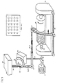
- FIG. 1 schematically represents a device of the prior art intended to recall the principle of the method of marking a rolling mill cylinder using an intermittent laser beam.
- the intermittent laser beam 36, 37 is transmitted to a marking head 42 which deflects it towards the surface d '' a rolling mill cylinder 40 supported between the points 43.
- the marking head 42 is driven in translation along the cylinder 40 by means of a lead screw 45.
- the chopping disc 35, the cylinder 40 and the lead screw 45 are driven in rotation by a motor 46, by means of distribution mechanisms ensuring the desired synchronization of the various movements.
- the width of the openings is equal to the distance separating two adjacent openings.
- a roughness consisting of substantially circular microcraters arranged in a regular manner, as shown in FIG. 1a which is an enlarged view of a range of the surface of the cylinder 40, after conventional marking.
- FIG 2 there is schematically shown a microcrater and a bead formed by an intermittent laser beam, in the presence of an oxygen jet, according to the prior art.
- the intermittent laser beam 1 focused by a lens 2 strikes the surface 3 of a rolling mill cylinder and causes the fusion of a metal droplet delimited by the broken line 4; beyond the surface symbolized by the broken line 4, the metal is heated to a certain depth, without reaching fusion.
- the molten metal 4 is partially expelled from its housing and it forms an asymmetrical bead 5 which surrounds a microcrater 6.
- the line 7 indicates an intermediate position of the droplet of molten metal during his movement of expulsion.
- the surface 3 of a rolling mill cylinder rotating around its axis in the direction of the arrow, is struck by an intermittent laser beam 1.
- the action of the enhanced laser pulse by an oxygen jet 13, causes the fusion of a metal droplet and the formation of a very localized plasma 14.
- the pressure of the plasma 14 and the oxygen jet 13 push the molten metal into a bead 5 which s 'spreads in part beyond the zone heated, without fusion, by the laser pulse.
- the bead does not adhere well to this colder zone and a crack 8 is formed which promotes the tearing of the bead during the subsequent rolling.
- FIG. 4 illustrates a situation similar to that of FIG. 2, where the jet of oxygen has been replaced by a jet of carbon dioxide, all the other operating conditions being unchanged.
- the droplet of molten metal forms a bead 5 'which remains in the form of a more abrupt pellet and much less extended than in Figure 2. It remains mainly above the molten area 4 where its adhesion is maximum.
- FIGS. 5 and 6 the shape and the position of the bead relative to the microcrater are illustrated, for the two orientations 9 and 10 of the gas jet respectively.
- the size of the microcraters and the beads is greatly exaggerated, in order to clearly show the difference between the two situations.
- FIG. 5 shows that the bead 5 is quite extended and that it clearly projects beyond the microcrater 6; moreover, it is deported to one side of the microcrater.
- FIG. 6 shows that, thanks to a gas jet 10 oriented in accordance with the present invention, the bead 5 remains symmetrical with respect to the microcrater 6.
- the bead 5 is here more compact and it is well welded to the surface of the cylinder, because it practically does not extend beyond the microcrater.
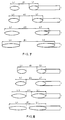
- FIG 7 there is shown the arrangement of two successive microcraters, in the direction of the periphery of the cylinder, for four different speeds of rotation of the chopper disc 35 ( Figure 1). These speeds, marked V1, V2, V3 and V4 were respectively worth 2500, 2200, 1900 and 1600 rpm. They not only cause an increasing elongation of the microcraters, but also an increasing spacing between them.
- FIG. 8 illustrates the influence of the widening of the openings of the chopping disc.
- this widening is obtained by a reduction in the spacing e between two adjacent openings, which makes it possible not to modify the number of these openings.
- FIG. 9 illustrates, in two views (a) and (b), the method of the invention for improving the adhesion of the bead.
- FIG. 9a The representation of FIG. 9a is identical to that of FIG. 3, with the difference that it comprises a second intermittent laser beam 15.
- the latter is represented here in dashed line, because it is itself interrupted during the first laser beam pulse 1.
- the bead thus acquires an adhesion which, combined with a high hardness, ensures a long service life for the rolling mill cylinder.
- FIG. 10 schematically represents a microcrater 6 and a bead 5 formed on the surface 3 of a rolling mill cylinder according to the invention, by an intermittent laser beam adjusted in an appropriate manner.
- the cylinder is symbolized by an axis of rotation, around which it rotates. Its surface is struck by an intermittent laser beam, each pulse of which causes the formation of a microcrater by a mechanism now well known. It will simply be recalled that at its point of impact, each pulse causes a certain volume of metal to heat up and, inside it, the fusion of a metal droplet 4. This molten metal is rejected radially towards the periphery of the heated zone, or possibly beyond this zone, where it forms a bead which solidifies very quickly.
- the conditions of the operation are regulated in such a way that the molten metal is, for the most part, rejected on one side.
- a bead 5 is thus obtained which partially surrounds a microcrater 6.
- the dashed line 4 marks the limit of the molten zone. It can be seen that the molten metal is partly rejected out of the molten zone 4.
- the conditions are such that the molten metal adheres very well to the hot surface, and that there is no crack between the base of the bead 5 and the surface of the cylinder. Consequently, there is no risk of the bead being torn off during the rolling of a sheet.
- the oxygen flow rate is adjusted so that the bead extends at most over a third of the periphery of the microcrater, the width 1 of the bead being less at 100 micrometers and its height h at most equal to 30 micrometers.
- 30% of the metal constituting said bead must be located inside the microcrater. Since this same operation is repeated at each microcrater, it follows that the beads are not joined.
- the surface of the cylinder thus has a multitude of peaks 5 separated by a network of valleys, the bottom of which is essentially constituted by all of the depressions 6.
- the relief shown schematically in FIG. 11 the hollow 5 ′ corresponds to the bead 5 and the plate 6 ′ corresponds to the depression 6.
- the sheet thus produced has a multitude of 5 'isolated troughs, regularly distributed over the surface of the sheet. The dimensions of these recesses correspond substantially to those of the beads which formed them.
- the lubricant When drawing such a sheet, the lubricant remains trapped in these recesses from which it cannot normally escape. If the tool pressure on the sheet is too high, the sheet tends to lengthen and the lubricant is partially expelled from the recesses located in the region concerned: it thus forms a lubricating film at the location critical. If, on the contrary, the pressure of the tool on the sheet is normal, the sheet slides while entraining the lubricant; it is therefore not scraped by the tools and it can be used for a more critical subsequent pass.
- the hollows made in the sheet of the invention can be very small and be very tight, while remaining insulated.
- the relief of the surface of the sheet thus becomes very little pronounced, which contributes to improving the appearance of the sheet after painting.
- Example 1 influence of the nature of the gas injected .
- the surface of a rolling mill cylinder was treated by means of an intermittent laser beam with a power of 1300 W, in the presence of a gas flow rate of 9 l / min.
- Table 1 shows that, for a practically identical microcrater, the bead corresponding to the CO2 jet is more compact and more salient than that which is obtained with an oxygen jet.
- Example 2 Influence of the orientation of the gas jet .
- the height (h) and the width (l) of the bead were measured at its highest point, the depth (p) and the width (D) of the microcrater at its deepest point, the roughness arithmetic (Ra) of the cylinder surface and the breakout force (F) of the beads.
- the results are collated in Table 2, where the dimensions and the roughness are expressed in micrometers while the pullout force is expressed in newtons.
- Example 3 Influence of the L / D ratio of the microcraters .
- FIG. 7 represents the arrangement of two successive microcraters, in the direction of the periphery of the cylinder, for four different speeds of rotation of the chopping disc.
- Table 4 below indicates the influence of the variation of the spacing e between two adjacent openings, on the length L and the L / D ratio of the microcraters.
- the width D was also worth 120 ⁇ m in all cases.
- the height h and the width l of the beads were also measured, as well as the depth p and the width D of the craters after formation of the beads.
- the increase in the length L of the microcraters leads to an increase in the L / D ratio, which is accompanied by a significant increase in the pull-out force F in Newton, that is to say of the adhesion of the beads .
- the improvement in adhesion is due to the fact that these beads form on the heated area of the surface of the cylinder; this effect is all the more marked as the microcrater is more elongated.
- the microcraters cannot be lengthened indefinitely because, when the L / D ratio reaches approximately 5, part of the molten metal of the bead flows backwards and partially fills the microcrater. The resulting bead is irregularly deformed.
Landscapes
- Engineering & Computer Science (AREA)
- Physics & Mathematics (AREA)
- Optics & Photonics (AREA)
- Mechanical Engineering (AREA)
- Plasma & Fusion (AREA)
- Chemical & Material Sciences (AREA)
- Thermal Sciences (AREA)
- Crystallography & Structural Chemistry (AREA)
- Materials Engineering (AREA)
- Metallurgy (AREA)
- Organic Chemistry (AREA)
- Fluid Mechanics (AREA)
- Laser Beam Processing (AREA)
- Metal Rolling (AREA)
- Reduction Rolling/Reduction Stand/Operation Of Reduction Machine (AREA)
Claims (9)
- Verfahren zur Markierung der Oberfläche eines Walzenzylinders, bei dem man den genannten Zylinder um seine Längsachse dreht und in der Oberfläche (3) des genannten Zylinders mit Hilfe eines intermittierenden Laserstrahls (1) und in Gegenwart eines auf die Auftreffzone des genannten Laserstrahls gerichteten Gasstrahls (13) eine Vielzahl von Mikrokratern bildet, wobei jeder Mikrokrater (6) einen Wulst (5) entstehen läßt, dadurch gekennzeichnet, daß man einen Gasstrahl (13) aus einem nichtoxidierenden Gas verwendet, und daß man die Ausströmmenge und den Einfallwinkel des genannten Gasstrahls (13) so regelt, daß Mikrokrater (6) gebildet werden, die nur auf einem Teil ihrer Peripherie einen Wulst (5) aufweisen.
- Markierungsverfahren nach Anspruch 1, bei dem das nichtoxidierende Gas ein reduzierendes Gas ist.
- Markierungsverfahren nach einem der Ansprüche 1 oder 2, dadurch gekennzeichnet, daß man den genannten Gasstrahl im wesentlichen senkrecht zu der Mantellinie des genannten Zylinders, die durch die genannte Auftreffzone verlaüft, ausrichtet.
- Markierungsverfahren nach Anspruch 3, dadurch gekennzeichnet, daß man das genannte Gas in der Richtung der Zylinderdrehung aufbläst.
- Markierungsverfahren nach einem der Ansprüche 1 bis 4, dadurch gekennzeichnet, daß man dem Verhältnis L/D zwischen der Größe L der Mikrokrater, gemessen entsprechend dem Zylinderumfang, und ihrer Größe D, gemessen parallel zur Längsachse des Zylinders, einen Wert zwischen 1 und 5 gibt.
- Markierungsverfahren nach Anspruch 5, dadurch gekennzeichnet, daß der Wert des Verhältnisses L/D zwischen 1,1 und 2,5 liegt.
- Markierungsverfahren nach einem der Ansprüche 1 bis 6, dadurch gekennzeichnet, daß man den genannten Wulst und den Bereich der Zylinderoberfläche, auf dem der genannte Wulst lagert, auf eine Temperatur erhitzt, die hoch genug ist, um ein Anschmelzen und das Verschweißen des genannten Wulstes mit dem genannten Bereich der Zylinderoberfläche hervorzurufen.
- Markierungsverfahren nach Anspruch 7, dadurch gekennzeichnet, daß man das genannte Erhitzen mit Hilfe eines zweiten Laserstrahls (15), insbesondere mit Hilfe eines abgelenkten Teilstrahls des genannten intermittierenden Laserstrahls (1), vornimmt.
- Verfahren zur Herstellung eines kaltgewalzten Stahlbleches, bei dem man in der Oberfläche mindestens eines Walzenzylinders mit Hilfe eines intermittierenden Laserstrahls (1) in Gegenwart eines auf die Auftreffzone des genannten Laserstrahls gerichteten Gasstrahls (13) eine Vielzahl von Mikrokratern bildet, wobei jeder Mikrokrater (6) einen Wulst (5) entstehen läßt, dadurch gekennzeichnet, daß man einen Gasstrahl aus einem nichtoxidierenden Gas verwendet, daß man die Ausströmmenge und den Einfallwinkel des genannten Gasstrahls so regelt, daß Mikrokrater gebildet werden, die nur auf einem Teil ihrer Peripherie einen Wulst aufweisen, daß man das genannte Blech mit Hilfe des genannten Zylinders walzt und daß man in der Oberfläche des Bleches einzelne, den Teilwülsten (5) des Zylinders entsprechende Vertiefungen (5') und den Mikrokratern (6) des Zylinders entsprechende Plateaus (6') bildet.
Priority Applications (1)
| Application Number | Priority Date | Filing Date | Title |
|---|---|---|---|
| AT88870022T ATE90890T1 (de) | 1987-02-23 | 1988-02-22 | Verfahren zur oberflaechenmarkierung von walzwerkswalzen. |
Applications Claiming Priority (12)
| Application Number | Priority Date | Filing Date | Title |
|---|---|---|---|
| LU86784A LU86784A1 (fr) | 1987-02-23 | 1987-02-23 | Cylindre de laminoir a rugosite amelioree et tole metallique produite au moyen dudit cylindre |
| LU86784 | 1987-02-23 | ||
| BE8700560 | 1987-05-19 | ||
| BE8700560A BE1000570A7 (fr) | 1987-05-19 | 1987-05-19 | Procede pour le traitement superficiel d'un cylindre de laminoir. |
| BE8700874A BE1000692A6 (fr) | 1987-07-14 | 1987-07-14 | Procede pour ameliorer la rugosite d'un cylindre de laminoir. |
| BE8700874 | 1987-07-14 | ||
| BE8701485A BE1001397A6 (fr) | 1987-12-24 | 1987-12-24 | Procede de marquage de la surface d'un cylindre de laminoir. |
| BE8701485 | 1987-12-24 | ||
| BE8800027 | 1988-01-11 | ||
| BE8800027A BE1001339A6 (fr) | 1988-01-11 | 1988-01-11 | Procede pour ameliorer la rugosite d'un cylindre de laminoir. |
| BE8800034A BE1001341A6 (fr) | 1988-01-13 | 1988-01-13 | Procede pour ameliorer la rugosite d'un cylindre de laminoir. |
| BE8800034 | 1988-01-13 |
Publications (3)
| Publication Number | Publication Date |
|---|---|
| EP0280671A2 EP0280671A2 (de) | 1988-08-31 |
| EP0280671A3 EP0280671A3 (en) | 1989-08-02 |
| EP0280671B1 true EP0280671B1 (de) | 1993-06-23 |
Family
ID=27543153
Family Applications (1)
| Application Number | Title | Priority Date | Filing Date |
|---|---|---|---|
| EP88870022A Expired - Lifetime EP0280671B1 (de) | 1987-02-23 | 1988-02-22 | Verfahren zur Oberflächenmarkierung von Walzwerkswalzen |
Country Status (4)
| Country | Link |
|---|---|
| US (1) | US4806731A (de) |
| EP (1) | EP0280671B1 (de) |
| JP (1) | JPH0767566B2 (de) |
| DE (1) | DE3881906T2 (de) |
Families Citing this family (43)
| Publication number | Priority date | Publication date | Assignee | Title |
|---|---|---|---|---|
| BE1002606A6 (fr) * | 1988-11-30 | 1991-04-09 | Centre Rech Metallurgique | Procede de fabrication d'un cylindre de laminoir. |
| US4996113A (en) * | 1989-04-24 | 1991-02-26 | Aluminum Company Of America | Brightness enhancement with textured roll |
| JPH02308291A (ja) * | 1989-05-24 | 1990-12-21 | Onoda Cement Co Ltd | 複写機用熱定着ロール及びその製造方法 |
| US5351399A (en) * | 1989-08-03 | 1994-10-04 | Schwabische Huttenwerke Gmbh | Method for forming grooves in roll surfaces |
| JPH03166071A (ja) * | 1989-11-27 | 1991-07-18 | Mitsubishi Heavy Ind Ltd | ウォータージェット式自動マーキング装置 |
| US5120395A (en) * | 1990-11-13 | 1992-06-09 | General Electric Company | Method for making a gas turbine engine component with a textured surface |
| WO1993004796A1 (fr) * | 1991-09-03 | 1993-03-18 | Nippon Steel Corporation | Procede de fabrication de toles d'acier a definition de peinture elevee et a aptitude elevee a l'estampage et cylindres depolis de laminage |
| DE4133620C1 (de) * | 1991-10-10 | 1993-04-22 | Maho Ag, 8962 Pfronten, De | |
| DE4329127A1 (de) * | 1993-08-30 | 1995-03-02 | Messer Griesheim Gmbh | Schutzgas für das Laserschweißen von Aluminium |
| US5508119A (en) * | 1994-09-07 | 1996-04-16 | Aluminum Company Of America | Enhanced work roll surface texture for cold and hot rolling of aluminum and its alloys |
| US5609778A (en) * | 1995-06-02 | 1997-03-11 | International Business Machines Corporation | Process for high contrast marking on surfaces using lasers |
| US5802947A (en) | 1996-10-15 | 1998-09-08 | Credo Tool Company | Dimpled circular saw blade |
| US5907144A (en) * | 1997-02-05 | 1999-05-25 | International Business Machines Corporation | Microscopic bar code for component identification and method for making same |
| US6549309B1 (en) | 1998-02-10 | 2003-04-15 | Illinois Tool Works Inc. | Holography apparatus, method and product |
| SG83780A1 (en) | 2000-03-07 | 2001-10-16 | Gintic Inst Of Mfg Technology | Process for laser marking metal surfaces |
| US6388780B1 (en) | 2000-05-11 | 2002-05-14 | Illinois Tool Works Inc. | Hologram production technique |
| GB0112234D0 (en) | 2001-05-18 | 2001-07-11 | Welding Inst | Surface modification |
| US6737971B2 (en) | 2001-06-07 | 2004-05-18 | Theodore F. Knaak | Apparatus for detecting an object approaching a vessel and associated method |
| DE10238557A1 (de) * | 2002-08-22 | 2004-03-04 | BSH Bosch und Siemens Hausgeräte GmbH | Verfahren und Vorrichtung zum Herstellen von düsenartigen Ausbrüchen in Sprüharmen für Geschirrspülmaschinen |
| US8102410B2 (en) * | 2005-10-26 | 2012-01-24 | Micronic Mydata AB | Writing apparatuses and methods |
| US8122846B2 (en) * | 2005-10-26 | 2012-02-28 | Micronic Mydata AB | Platforms, apparatuses, systems and methods for processing and analyzing substrates |
| KR100654360B1 (ko) * | 2005-10-27 | 2006-12-08 | 삼성전자주식회사 | 반도체 집적 회로 장치와 그 제조 방법 |
| US8262381B2 (en) * | 2006-06-22 | 2012-09-11 | Sabic Innovative Plastics Ip B.V. | Mastering tools and systems and methods for forming a cell on the mastering tools |
| US7807938B2 (en) * | 2006-06-22 | 2010-10-05 | Sabic Innovative Plastics Ip B.V. | Mastering tools and systems and methods for forming a plurality of cells on the mastering tools |
| US20080305279A1 (en) * | 2006-10-31 | 2008-12-11 | Duncan Young | Method of marking a surgical article |
| US7985941B2 (en) * | 2007-11-16 | 2011-07-26 | 3M Innovative Properties Company | Seamless laser ablated roll tooling |
| EP2521798B8 (de) * | 2009-07-15 | 2015-02-25 | Politechnika Swietokrzyska | Verfahren zur vergrösserung von wärmetauscherflächen von metall- und metallegierungelementen |
| EP2336586B1 (de) * | 2009-12-15 | 2013-08-14 | Maxon Motor AG | Verfahren zum Erzeugen eines Presssitzes eines Bauteils auf einer Welle |
| CN102259172B (zh) * | 2010-05-25 | 2013-04-24 | 宝山钢铁股份有限公司 | 薄带连铸结晶辊表面毛化方法 |
| WO2013020115A2 (en) | 2011-08-04 | 2013-02-07 | Milwaukee Electric Tool Corporation | Reciprocating saw blade |
| ITMI20112330A1 (it) | 2011-12-21 | 2013-06-22 | Tenova Spa | Macchina operatrice e relativo metodo per il trattamento superficiale di cilindri |
| USD688543S1 (en) | 2012-03-20 | 2013-08-27 | Milwaukee Electric Tool Corporation | Saw blade |
| DE102012017703A1 (de) * | 2012-09-07 | 2014-03-13 | Daetwyler Graphics Ag | Flachprodukt aus Metallwerkstoff, insbesondere einem Stahlwerkstoff, Verwendung eines solchen Flachprodukts sowie Walze und Verfahren zur Herstellung solcher Flachprodukte |
| USD729600S1 (en) | 2014-05-06 | 2015-05-19 | Milwaukee Electric Tool Corporation | Saw blade |
| US10639746B1 (en) * | 2014-06-20 | 2020-05-05 | Apple Inc. | Ceramic-based components having laser-etched markings |
| US10144107B2 (en) | 2015-09-30 | 2018-12-04 | Apple Inc. | Ultrasonic polishing systems and methods of polishing brittle components for electronic devices |
| US10493508B2 (en) * | 2015-10-14 | 2019-12-03 | Novelis Inc. | Engineered work roll texturing |
| CN106994561B (zh) * | 2016-01-26 | 2019-07-12 | 大族激光科技产业集团股份有限公司 | 一种动态旋转打标控制系统和控制方法 |
| US11113494B2 (en) | 2019-11-11 | 2021-09-07 | Apple Inc. | Biometric key including a textured ceramic cover |
| CN112783264A (zh) | 2019-11-11 | 2021-05-11 | 苹果公司 | 包括纹理化陶瓷盖的生物识别按键 |
| CN110961791B (zh) * | 2019-12-24 | 2021-10-19 | 北京科技大学 | 一种电火花和激光复合毛化装置 |
| CN112122784B (zh) * | 2020-09-01 | 2021-05-14 | 中国科学院力学研究所 | 一种光纤激光毛化两维无序分布控制方法 |
| CN114505301B (zh) * | 2022-02-23 | 2022-12-02 | 西南交通大学 | 一种分区负压式激光清洗设备及方法 |
Family Cites Families (9)
| Publication number | Priority date | Publication date | Assignee | Title |
|---|---|---|---|---|
| GB1215713A (en) * | 1967-03-16 | 1970-12-16 | Nat Res Dev | Improvements relating to thermal cutting apparatus |
| DE2458370C2 (de) * | 1974-12-10 | 1984-05-10 | Dr.-Ing. Rudolf Hell Gmbh, 2300 Kiel | Energiestrahl-Gravierverfahren und Einrichtung zu seiner Durchführung |
| JPS5947827B2 (ja) * | 1977-07-22 | 1984-11-21 | 静岡製機株式会社 | 穀物の乾燥方法 |
| DE2840702A1 (de) * | 1977-09-22 | 1979-04-05 | Centre Rech Metallurgique | Verfahren und vorrichtung zur qualitaetsverbesserung von stahlfeinblechen |
| LU80792A1 (fr) * | 1979-01-15 | 1980-08-08 | Ntre De Rech Metallurg Ct Voor | Dispsitif et procede pour effectuer des perforations a la surface des cylindres de laminoirs |
| US4377736A (en) * | 1981-08-14 | 1983-03-22 | General Electric Company | Method and apparatus for removing material from a surface |
| US4734729A (en) * | 1985-08-06 | 1988-03-29 | Eastman Kodak Company | Studded squeegee roller |
| US4806724A (en) * | 1986-08-15 | 1989-02-21 | Kawasaki Steel Corp. | Laser beam machining device |
| BE1000458A6 (fr) * | 1987-04-08 | 1988-12-13 | Centre Rech Metallurgique | Procede de mesure de la resistance a l'abrasion de la rugosite d'une surface metallique. |
-
1988
- 1988-02-22 EP EP88870022A patent/EP0280671B1/de not_active Expired - Lifetime
- 1988-02-22 DE DE88870022T patent/DE3881906T2/de not_active Expired - Fee Related
- 1988-02-23 JP JP63040555A patent/JPH0767566B2/ja not_active Expired - Fee Related
- 1988-02-23 US US07/159,138 patent/US4806731A/en not_active Expired - Fee Related
Also Published As
| Publication number | Publication date |
|---|---|
| DE3881906D1 (de) | 1993-07-29 |
| EP0280671A3 (en) | 1989-08-02 |
| JPH0767566B2 (ja) | 1995-07-26 |
| JPS6422406A (en) | 1989-01-25 |
| EP0280671A2 (de) | 1988-08-31 |
| US4806731A (en) | 1989-02-21 |
| DE3881906T2 (de) | 1994-01-20 |
Similar Documents
| Publication | Publication Date | Title |
|---|---|---|
| EP0280671B1 (de) | Verfahren zur Oberflächenmarkierung von Walzwerkswalzen | |
| EP0119182B1 (de) | Verfahren zur Verbesserung der Oberflächeneigenschaften von Walzen | |
| EP2605880B1 (de) | Bogenschweissvorrichtung und -verfahren unter verwendung eines mig/mag-brenners in kombination mit einem wig-brenner | |
| EP3393706B1 (de) | Verfahren zur herstellung eines vorbeschichteten metallblechs unter entfernung der beschichtung mittels eines geneigten laserstrahls und entsprechendes metallblech | |
| EP1923165A1 (de) | Laserschweißverfahren mit verbesserter Penetration | |
| EP0057651A2 (de) | Verfahren zum schnellen Erstarren und Abkühlen durch Stranggiessen von geschmolzenen Materialien auf der Basis von Metalloxiden | |
| EP0278942A1 (de) | Verfahren zur Oberflächenbehandlung einer Walze | |
| EP0896853B1 (de) | Verfahren und Vorrichtung zum Herstellen von geschweisste Metallrohren | |
| LU86606A1 (fr) | Electrode metallique tubulaire a ame et utilisation de cette electrode pour le coupage a l'arc des metaux | |
| EP0324327B1 (de) | Verfahren zum Markieren der Oberfläche einer Walze | |
| CA2334985C (fr) | Procede pour realiser un support de flammes | |
| CA2868207A1 (fr) | Buse laser avec element mobile a profil externe ameliore | |
| EP0546885B1 (de) | Zylinder für eine Stranggiessvorrichtung zum Giessen von Metallbändern, entsprechende Stranggiessvorrichtung und Verfahren zur Herstellung eines derartigen Zylinders | |
| CA2030610C (fr) | Procede et dispositif de coulee continue sur un ou entre deux cylindres | |
| CA1093782A (fr) | Procede de coulee continue entre deux series d'elements cylindriques refroidis et mobiles exercant une pression sur le metal en voie de solidification | |
| EP0618036B1 (de) | Verfahren und Vorrichtung zur Bearbeitung mit einem Laserstrahl | |
| FR2505696A1 (fr) | Procede de fabrication de pieces a revetement de metal depose par soudure a l'arc et piece fabriquee en utilisant ledit procede | |
| EP2408585B1 (de) | Lötschweissvorrichtung | |
| BE1001397A6 (fr) | Procede de marquage de la surface d'un cylindre de laminoir. | |
| FR3010339A1 (fr) | Procede de soudage par faisceau laser sur tole sandwich avec controle de l'ouverture du capillaire | |
| EP0271469B1 (de) | Verfahren zum Bilden von Mikroperforationen auf der Fläche eines Walzzylinders | |
| BE1000570A7 (fr) | Procede pour le traitement superficiel d'un cylindre de laminoir. | |
| CA1026925A (en) | Method and device for the manufacture of a rolled product from stock obtained through continuous casting in a sheave | |
| FR2959516A1 (fr) | Procede de pretraitement de structuration d'une surface de coulissement | |
| FR2726209A1 (fr) | Surface de coulee d'une lingotiere de coulee continue des metaux a paroi mobile |
Legal Events
| Date | Code | Title | Description |
|---|---|---|---|
| PUAI | Public reference made under article 153(3) epc to a published international application that has entered the european phase |
Free format text: ORIGINAL CODE: 0009012 |
|
| AK | Designated contracting states |
Kind code of ref document: A2 Designated state(s): AT DE FR GB IT LU SE |
|
| PUAL | Search report despatched |
Free format text: ORIGINAL CODE: 0009013 |
|
| AK | Designated contracting states |
Kind code of ref document: A3 Designated state(s): AT DE FR GB IT LU SE |
|
| 17P | Request for examination filed |
Effective date: 19900117 |
|
| 17Q | First examination report despatched |
Effective date: 19911106 |
|
| GRAA | (expected) grant |
Free format text: ORIGINAL CODE: 0009210 |
|
| AK | Designated contracting states |
Kind code of ref document: B1 Designated state(s): AT DE FR GB IT LU SE |
|
| PG25 | Lapsed in a contracting state [announced via postgrant information from national office to epo] |
Ref country code: IT Free format text: LAPSE BECAUSE OF FAILURE TO SUBMIT A TRANSLATION OF THE DESCRIPTION OR TO PAY THE FEE WITHIN THE PRE;WARNING: LAPSES OF ITALIAN PATENTS WITH EFFECTIVE DATE BEFORE 2007 MAY HAVE OCCURRED AT ANY TIME BEFORE 2007. THE CORRECT EFFECTIVE DATE MAY BE DIFFERENT FROM THE ONE RECORDED.SCRIBED TIME-LIMIT Effective date: 19930623 Ref country code: SE Effective date: 19930623 |
|
| REF | Corresponds to: |
Ref document number: 90890 Country of ref document: AT Date of ref document: 19930715 Kind code of ref document: T |
|
| REF | Corresponds to: |
Ref document number: 3881906 Country of ref document: DE Date of ref document: 19930729 |
|
| GBT | Gb: translation of ep patent filed (gb section 77(6)(a)/1977) |
Effective date: 19930923 |
|
| PG25 | Lapsed in a contracting state [announced via postgrant information from national office to epo] |
Ref country code: LU Free format text: LAPSE BECAUSE OF NON-PAYMENT OF DUE FEES Effective date: 19940228 |
|
| PLBE | No opposition filed within time limit |
Free format text: ORIGINAL CODE: 0009261 |
|
| STAA | Information on the status of an ep patent application or granted ep patent |
Free format text: STATUS: NO OPPOSITION FILED WITHIN TIME LIMIT |
|
| 26N | No opposition filed | ||
| PGFP | Annual fee paid to national office [announced via postgrant information from national office to epo] |
Ref country code: FR Payment date: 19950123 Year of fee payment: 8 |
|
| PGFP | Annual fee paid to national office [announced via postgrant information from national office to epo] |
Ref country code: AT Payment date: 19950213 Year of fee payment: 8 |
|
| PGFP | Annual fee paid to national office [announced via postgrant information from national office to epo] |
Ref country code: DE Payment date: 19951213 Year of fee payment: 9 |
|
| PGFP | Annual fee paid to national office [announced via postgrant information from national office to epo] |
Ref country code: GB Payment date: 19960213 Year of fee payment: 9 |
|
| PG25 | Lapsed in a contracting state [announced via postgrant information from national office to epo] |
Ref country code: AT Effective date: 19960222 |
|
| PG25 | Lapsed in a contracting state [announced via postgrant information from national office to epo] |
Ref country code: FR Effective date: 19961031 |
|
| REG | Reference to a national code |
Ref country code: FR Ref legal event code: ST |
|
| PG25 | Lapsed in a contracting state [announced via postgrant information from national office to epo] |
Ref country code: GB Effective date: 19970222 |
|
| GBPC | Gb: european patent ceased through non-payment of renewal fee |
Effective date: 19970222 |
|
| PG25 | Lapsed in a contracting state [announced via postgrant information from national office to epo] |
Ref country code: DE Effective date: 19971101 |