EP0279737A2 - Schneidvorrichtung für Kunststoffrohre mit geführtem Messer - Google Patents
Schneidvorrichtung für Kunststoffrohre mit geführtem Messer Download PDFInfo
- Publication number
- EP0279737A2 EP0279737A2 EP88400317A EP88400317A EP0279737A2 EP 0279737 A2 EP0279737 A2 EP 0279737A2 EP 88400317 A EP88400317 A EP 88400317A EP 88400317 A EP88400317 A EP 88400317A EP 0279737 A2 EP0279737 A2 EP 0279737A2
- Authority
- EP
- European Patent Office
- Prior art keywords
- blade
- tube
- cutter
- guided
- cut
- Prior art date
- Legal status (The legal status is an assumption and is not a legal conclusion. Google has not performed a legal analysis and makes no representation as to the accuracy of the status listed.)
- Granted
Links
Images


Classifications
-
- B—PERFORMING OPERATIONS; TRANSPORTING
- B23—MACHINE TOOLS; METAL-WORKING NOT OTHERWISE PROVIDED FOR
- B23D—PLANING; SLOTTING; SHEARING; BROACHING; SAWING; FILING; SCRAPING; LIKE OPERATIONS FOR WORKING METAL BY REMOVING MATERIAL, NOT OTHERWISE PROVIDED FOR
- B23D21/00—Machines or devices for shearing or cutting tubes
- B23D21/06—Hand-operated tube-cutters
- B23D21/10—Hand-operated tube-cutters with other cutting blades or tools
-
- B—PERFORMING OPERATIONS; TRANSPORTING
- B26—HAND CUTTING TOOLS; CUTTING; SEVERING
- B26D—CUTTING; DETAILS COMMON TO MACHINES FOR PERFORATING, PUNCHING, CUTTING-OUT, STAMPING-OUT OR SEVERING
- B26D3/00—Cutting work characterised by the nature of the cut made; Apparatus therefor
- B26D3/16—Cutting rods or tubes transversely
- B26D3/169—Hand held tube cutters
Definitions
- the present invention relates to a manual device for cutting plastic or cylindrical plastic tubes of the kind comprising a guide arch closed by a lower arch with full opening allowing intervention on the pipes in place as easily as on those in progress of installation. If there are no major difficulties in cutting the plastic tubes most commonly used today, the same is not true for high density polyethylene tubes delivered in crowns, the use of which is becoming more widespread. at the instigation of Public Services in the following areas: transport of corrosive products, water supply, sanitation, faulty pipe casing, gas distribution. These tubes, due to their mode of delivery in crowns or on reels which are always strongly ovalized, and due to their great thickness, they exhibit great rigidity.
- the present invention provides a very different blade cutter from what currently exists. It allows easy cutting of polyethylene tubes at right angles, regardless of their ovalization, in the workshop as well as on site without the need for a support point.
- the cut made is a cut without removing material, therefore without chips, which can only satisfy Gaz de France Technical Services, which will appreciate not finding any more chips in the counters that fell into the pipes during maintenance operations or network modification.
- this tube cutter and not least is that it can be used in a very narrow trench because the cut which is carried out without rotation of the device around the tube does not even require travel. Its small size below and on each side of the tube obtained by the shape of the lower arch and the presence of the blade in the upper arch makes it possible to significantly reduce the volume of soil to be released under the tube before the intervention . Once the tube cutter is in place on the tube, the latter serving as a support, it only remains to tighten the control screw using the operating rod or a crutch wrench to make the cut either from inside the trench, either from the outside.
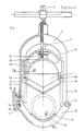
- the blade 1 of this pipe cutter is mounted on a blade holder 2 which moves under the action of a control screw 3 between the two parallel branches of an arch -guide 4 closed by a lower arch 10 held in place on one side by the hinge pin 11 and on the other by a locking device 7 on which one can act so that this arch can pivot around its axis articulation until full opening; which allows the tube cutter to be placed directly astride the tube to be cut 9.
- the control screw 3 is provided with an operating rod 5 and a drive square 6 allowing either to be connected to an assembly motorization, or to rotate it using a key for operating a buried pipe valve of the type of socket wrenches used by the services of Gaz de France.
- the curvilinear section bench 8 or of any other shape depending on the profile to be cut comes into contact with the tube on which it is plate, thus forcing the tube cutter to be placed at right angles to said sectioning tube 9 which, tightened in this way, acts as a support for the tube cutter throughout the duration of the cutting operation.
- the upper part of the blade holder 2 receives the thrust from the control screw 3 by means of a stop or a steel ball 21 rotating on a grain 22 while the part lower presents between the two fixing points 24, 20 of the blade a semi-circular recess 23 of diameter slightly larger than that of the largest tube to be cut.
- the guide of the blade holder 2 between the two branches of the yoke 4 can be achieved in two different ways: machined surfaces are provided on the outer parts 12, 13 of each branch which must be in contact with the blade holder so that it can slide on it (fig.2) or else these surfaces are provided on the inner parts 14, 15 of these same wings so that the blade holder can slide there internally.
- the width of the cutting blade can be equal to that of the blade holder 2 comprised between its projecting parts (16) 19 moving between the wings of the two branches of the yoke-guide 4 visible in Figure 1. It follows that for a given blade width, the size of the yoke-guide is very small.
- the thickness of the blade holder at the level of the recess (23) can be increased until being equal to that of the bench (8) of the lower arch so that at the end of the cut its semi-circular shape comes to wrap sufficiently the tube under stress on each side of the blade to prevent sudden expansion of the sectioned sections which is generally very dangerous for the operator as the stresses existing between the unwound part of the tube and that remaining on the reel are important.
- Figure 4 with the section along BB shown in Figure 5 shows another form of lower arch in which the curvilinear section bench has been replaced by flat metal plates 25, 26 having like the latter a notch 27 located in the cutting plane blade to allow said blade to come to complete its race below said plates thereby ensuring complete cutting of the tube to be cut.
- This notch 27 must always be free for the passage of the blade, a shorter and wider opening 28 made along the same axis in the lower part of the lower arch prevents any dirt being found on the tube to be cut from obstruct said notch by accumulating in the bottom of the arch.
- this tube cutter being a site device capable of being used in muddy places, this opening 28 facilitates cleaning.
- Figure 6 shows a cutting blade whose angle at the top ( , ) is 120 ° because by choosing it between 100 and 150 degrees it allows an attack of the tube without deformation.
- This angle of 120 degrees which is equal to that existing between the two flat metal plates 25, 26 of the lower arch makes it possible to obtain complete cutting of the tube with a minimum of elastic deformation and with a minimum of penetration of the blade in notch 27.
- the cutting edge 29 of said blade is in this position perfectly protected by the sides of the lower arch and the pipe cutter can be transported safely in the state it is in once the cut finished.
- the section of the cutting blade is symmetrical and that it has a slope break. This symmetry is necessary to obtain a perfectly square cut.
- FIG. 8 shows the pinch fastening method which is used for thin cutting blades called "thin".
- the lower ends of the blade holder 2 are provided with yokes 30 whose elasticity is used to obtain the desired clamping of the blade by simply tightening the screws 31.
- Figure 9 shows a variant of the fixing method easier to perform but usable only in the case of the use of a thick blade which although maintained on one side has sufficient rigidity not to deviate from the cutting plane under the lateral forces encountered in normal use.
- this type of pipe cutter must be able to be transported from one place to another in complete safety.
- the blade holder pushes the attachment pin 32 of the lower yoke into the bottom of the groove 33 of the latch 7 visible in FIG. 1 and thus unlocking allowing the opening of the yoke by simple pressure on the upper part 34 of the latch 7 is impossible.
- the cut is quick because it suffices to reassemble the blade by turning the control screw 3 and to open the cutter. tube by simple pressure on the upper part of the latch 7 to be able to close it on the tube which is then sectioned by the descent of the blade under the action of the control screw which is then rotated in the opposite direction.
- the gripping and transport of the larger of these pipe cutters according to the invention can be improved by adding a handle in the form of a hoop which is fixed on the upper part of the yoke-guide, this which changes the aesthetics but does not increase the size and still allows you to work in narrow trenches whose width may not exceed 2.5 times the diameter of the largest tube accepted by the device.
- This guided blade pipe cutter is therefore a device allowing to quickly and safely cut polyethylene tubes and most plastic cylindrical or non-difficult plastic tubes to cut with the wheel tube cutters. Its field of use is that of the installation and maintenance of these tubes, in particular the water supply, the defective pipe casing and the gas distribution.
Landscapes
- Engineering & Computer Science (AREA)
- Mechanical Engineering (AREA)
- Life Sciences & Earth Sciences (AREA)
- Forests & Forestry (AREA)
- Knives (AREA)
- Nonmetal Cutting Devices (AREA)
- Scissors And Nippers (AREA)
Applications Claiming Priority (2)
| Application Number | Priority Date | Filing Date | Title |
|---|---|---|---|
| FR8702425 | 1987-02-19 | ||
| FR8702425A FR2611162B3 (fr) | 1987-02-19 | 1987-02-19 | Coupe-tube a lame guidee pour tubes en matiere plastique cylindriques ou non |
Publications (3)
| Publication Number | Publication Date |
|---|---|
| EP0279737A2 true EP0279737A2 (de) | 1988-08-24 |
| EP0279737A3 EP0279737A3 (en) | 1990-07-18 |
| EP0279737B1 EP0279737B1 (de) | 1994-01-19 |
Family
ID=9348246
Family Applications (1)
| Application Number | Title | Priority Date | Filing Date |
|---|---|---|---|
| EP88400317A Expired - Lifetime EP0279737B1 (de) | 1987-02-19 | 1988-02-12 | Schneidvorrichtung für Kunststoffrohre mit geführtem Messer |
Country Status (4)
| Country | Link |
|---|---|
| US (1) | US4845849A (de) |
| EP (1) | EP0279737B1 (de) |
| DE (1) | DE3887177T2 (de) |
| FR (1) | FR2611162B3 (de) |
Cited By (3)
| Publication number | Priority date | Publication date | Assignee | Title |
|---|---|---|---|---|
| EP0769355A1 (de) * | 1995-10-07 | 1997-04-23 | Koeitsusho Kabushiki Kaisha | Schneidgerät für Kunststoffflaschen |
| EP3450070A1 (de) * | 2017-08-31 | 2019-03-06 | Wavin B.V. | Handhaltbarer rohrschneider mit einem sicherer und verfahren zum schneiden eines rohrs |
| US10588449B2 (en) | 2017-10-16 | 2020-03-17 | Steven Jay Self | Cutting device |
Families Citing this family (19)
| Publication number | Priority date | Publication date | Assignee | Title |
|---|---|---|---|---|
| CA2048780C (en) * | 1991-08-08 | 1997-12-16 | Edward Joseph Schartinger | Blade for cutting cylindrical structures |
| US5377410A (en) * | 1993-10-25 | 1995-01-03 | Welch; Wade | Cutter for strand-encircling sheaths |
| US5956853A (en) * | 1997-06-10 | 1999-09-28 | Watamura; Abe | Pipe cutting tool for plastic pipe |
| USD435209S (en) * | 1999-10-06 | 2000-12-19 | Armament Systems And Procedures, Inc. | Cutting device |
| US6349472B1 (en) * | 1999-10-06 | 2002-02-26 | Armament Systems And Procedures, Inc. | Cutting device |
| US6671962B2 (en) | 2001-06-04 | 2004-01-06 | Abe Watamura | Pipe cutting tool for plastic pipe |
| NO322114B1 (no) * | 2004-08-24 | 2006-08-14 | Uni For Miljo Og Biovitenskap | Rorkutter |
| CN100460115C (zh) * | 2005-01-05 | 2009-02-11 | 叶咏梅 | 可调式管子割刀 |
| GB2459829B (en) | 2007-03-15 | 2012-02-01 | Milwaukee Electric Tool Corp | Pipe cutter |
| DE112008003266T5 (de) * | 2007-11-28 | 2010-10-07 | Milwaukee Electric Tool Corp., Brookfield | Rohrschneider |
| WO2011148192A2 (en) * | 2010-05-28 | 2011-12-01 | National Oilwell Varco, L.P. | System and method for severing a tubular |
| US8162046B2 (en) | 2010-08-17 | 2012-04-24 | T-3 Property Holdings, Inc. | Blowout preventer with shearing blades |
| US8632047B2 (en) * | 2011-02-02 | 2014-01-21 | Hydril Usa Manufacturing Llc | Shear blade geometry and method |
| RU2598014C1 (ru) * | 2015-04-21 | 2016-09-20 | Виктор Сергеевич Быков | Устройство для резки труб из полипропилена |
| CN205218181U (zh) | 2015-06-15 | 2016-05-11 | 米沃奇电动工具公司 | 管道切割器 |
| USD813006S1 (en) | 2015-06-15 | 2018-03-20 | Milwaukee Electric Tool Corporation | Knob for a cutter |
| CA3113452C (en) | 2015-08-07 | 2022-10-11 | Hubbell Incorporated | Portable hand tool and kit |
| CN105058463A (zh) * | 2015-08-28 | 2015-11-18 | 岑立强 | 一种塑料管用电动卧式切管机 |
| CN110509331B (zh) * | 2019-08-16 | 2021-08-06 | 江西强发科技有限公司 | 一种pvc管道切割结构 |
Citations (3)
| Publication number | Priority date | Publication date | Assignee | Title |
|---|---|---|---|---|
| GB378654A (en) * | 1931-09-01 | 1932-08-18 | George Geach Parnall | Improvements in or relating to tube cutting tools |
| US2248642A (en) * | 1938-11-26 | 1941-07-08 | Howard T Saperston | Device for cutting cables and the like |
| US2539124A (en) * | 1949-04-15 | 1951-01-23 | Ellwood W Findlay | Tube cutting device |
Family Cites Families (2)
| Publication number | Priority date | Publication date | Assignee | Title |
|---|---|---|---|---|
| US1156745A (en) * | 1915-05-01 | 1915-10-12 | Joseph D Brady | Tool for splitting nuts. |
| GB277558A (en) * | 1927-02-23 | 1927-09-22 | Samuel Armstrong | An improved apparatus for dehorning cattle |
-
1987
- 1987-02-19 FR FR8702425A patent/FR2611162B3/fr not_active Expired
-
1988
- 1988-02-12 DE DE3887177T patent/DE3887177T2/de not_active Expired - Fee Related
- 1988-02-12 EP EP88400317A patent/EP0279737B1/de not_active Expired - Lifetime
- 1988-02-19 US US07/157,787 patent/US4845849A/en not_active Expired - Lifetime
Patent Citations (3)
| Publication number | Priority date | Publication date | Assignee | Title |
|---|---|---|---|---|
| GB378654A (en) * | 1931-09-01 | 1932-08-18 | George Geach Parnall | Improvements in or relating to tube cutting tools |
| US2248642A (en) * | 1938-11-26 | 1941-07-08 | Howard T Saperston | Device for cutting cables and the like |
| US2539124A (en) * | 1949-04-15 | 1951-01-23 | Ellwood W Findlay | Tube cutting device |
Cited By (5)
| Publication number | Priority date | Publication date | Assignee | Title |
|---|---|---|---|---|
| EP0769355A1 (de) * | 1995-10-07 | 1997-04-23 | Koeitsusho Kabushiki Kaisha | Schneidgerät für Kunststoffflaschen |
| US5740612A (en) * | 1995-10-07 | 1998-04-21 | Koeitsusho Kabushiki Kaisha | Plastic bottle cutting implement |
| EP3450070A1 (de) * | 2017-08-31 | 2019-03-06 | Wavin B.V. | Handhaltbarer rohrschneider mit einem sicherer und verfahren zum schneiden eines rohrs |
| NL1042524B1 (en) * | 2017-08-31 | 2019-03-11 | Wavin Bv | Handheld pipe cutter comprising a securer and a method of cutting a pipe |
| US10588449B2 (en) | 2017-10-16 | 2020-03-17 | Steven Jay Self | Cutting device |
Also Published As
| Publication number | Publication date |
|---|---|
| EP0279737A3 (en) | 1990-07-18 |
| FR2611162B3 (fr) | 1989-06-16 |
| DE3887177D1 (de) | 1994-03-03 |
| US4845849A (en) | 1989-07-11 |
| DE3887177T2 (de) | 1994-07-21 |
| FR2611162A1 (fr) | 1988-08-26 |
| EP0279737B1 (de) | 1994-01-19 |
Similar Documents
| Publication | Publication Date | Title |
|---|---|---|
| EP0279737B1 (de) | Schneidvorrichtung für Kunststoffrohre mit geführtem Messer | |
| FR2481338A1 (fr) | Dent amovible pour excavateur | |
| FR2860701A1 (fr) | Dispositif et procede de sectionnement de la lame d'une vertebre | |
| FR2753120A1 (fr) | Dispositif de pince coupe-tube pour couper transversalement un tube en matiere plastique | |
| EP0532391B1 (de) | Zange zum Zusammendrücken von Rohren, etwa einer Gasleitung | |
| FR2775679A1 (fr) | Ouvre-boite | |
| FR1464371A (fr) | Rotor pour appareils destinés à la désagrégation de la paille ou matière similaire | |
| EP1075220A1 (de) | Verbindungsvorrichtung für chirurgisches instrument | |
| EP0102864A2 (de) | Rohrschneider mit Schneidrädchen und bogenförmigen Teilen | |
| WO2019008240A1 (fr) | Dispositif d'enroulement d'un tube souple | |
| EP0006374B1 (de) | Vorrichtung zum Spannen von Ketten und Satz von auswechselbaren Ketten zum Schneiden oder zum Umspannen von Rohren | |
| EP0216683B1 (de) | Ein Magazin bildendes Werkzeug zum Anbringen irgend eines Artikels, insbesondere für Verkabelungskennzeichnungen | |
| FR2952625A1 (fr) | Outil de levage de plaques de voirie | |
| FR2698570A1 (fr) | Coupe-tubes à chanfreineur incorporé et à avance irréversible pour coupe par cisaillage des tubes en matière plastique à forte élasticité. | |
| EP1466646A1 (de) | Sicherheitsvorrichtung gegen freier Strömung | |
| FR2626441A1 (fr) | Machine a eplucher et couper les poireaux | |
| FR2853617A1 (fr) | Cycle muni d'un moyen de guidage | |
| FR3020075B1 (fr) | Roto deneige | |
| FR2500344A1 (fr) | Perfectionnements apportes aux cisailles hydrauliques | |
| FR2510022A1 (en) | Spanner for square headed spindles - uses handle on screw-jack to drive wedge between tail arms of pivotal jaws with V=section grooves | |
| FR2758449A1 (fr) | Dipositif manuel pour ouvrir les huitres | |
| FR2691387A1 (fr) | Appareil de remise en forme de pièces tubulaires. | |
| EP0207823A1 (de) | Zange zum Öffnen von unter Druck stehenden Behältern | |
| EP0084496B1 (de) | Anlage zum Öffnen von unter Väkuum stehenden Einmachgefässen | |
| BE1006906A5 (fr) | Outil de fraisage et dispositif de percage, permettant notamment le percage de parois de tuyauteries. |
Legal Events
| Date | Code | Title | Description |
|---|---|---|---|
| PUAI | Public reference made under article 153(3) epc to a published international application that has entered the european phase |
Free format text: ORIGINAL CODE: 0009012 |
|
| AK | Designated contracting states |
Kind code of ref document: A2 Designated state(s): DE ES FR GB IT |
|
| PUAL | Search report despatched |
Free format text: ORIGINAL CODE: 0009013 |
|
| AK | Designated contracting states |
Kind code of ref document: A3 Designated state(s): DE ES FR GB IT |
|
| 17P | Request for examination filed |
Effective date: 19901024 |
|
| 17Q | First examination report despatched |
Effective date: 19911125 |
|
| GRAA | (expected) grant |
Free format text: ORIGINAL CODE: 0009210 |
|
| AK | Designated contracting states |
Kind code of ref document: B1 Designated state(s): DE ES FR GB IT |
|
| PG25 | Lapsed in a contracting state [announced via postgrant information from national office to epo] |
Ref country code: IT Free format text: LAPSE BECAUSE OF FAILURE TO SUBMIT A TRANSLATION OF THE DESCRIPTION OR TO PAY THE FEE WITHIN THE PRESCRIBED TIME-LIMIT;WARNING: LAPSES OF ITALIAN PATENTS WITH EFFECTIVE DATE BEFORE 2007 MAY HAVE OCCURRED AT ANY TIME BEFORE 2007. THE CORRECT EFFECTIVE DATE MAY BE DIFFERENT FROM THE ONE RECORDED. Effective date: 19940119 Ref country code: ES Free format text: THE PATENT HAS BEEN ANNULLED BY A DECISION OF A NATIONAL AUTHORITY Effective date: 19940119 |
|
| REF | Corresponds to: |
Ref document number: 3887177 Country of ref document: DE Date of ref document: 19940303 |
|
| GBT | Gb: translation of ep patent filed (gb section 77(6)(a)/1977) |
Effective date: 19940308 |
|
| PLBE | No opposition filed within time limit |
Free format text: ORIGINAL CODE: 0009261 |
|
| STAA | Information on the status of an ep patent application or granted ep patent |
Free format text: STATUS: NO OPPOSITION FILED WITHIN TIME LIMIT |
|
| 26N | No opposition filed | ||
| PGFP | Annual fee paid to national office [announced via postgrant information from national office to epo] |
Ref country code: GB Payment date: 19980211 Year of fee payment: 11 |
|
| PGFP | Annual fee paid to national office [announced via postgrant information from national office to epo] |
Ref country code: FR Payment date: 19980227 Year of fee payment: 11 |
|
| PGFP | Annual fee paid to national office [announced via postgrant information from national office to epo] |
Ref country code: DE Payment date: 19980430 Year of fee payment: 11 |
|
| PG25 | Lapsed in a contracting state [announced via postgrant information from national office to epo] |
Ref country code: GB Free format text: LAPSE BECAUSE OF NON-PAYMENT OF DUE FEES Effective date: 19990212 |
|
| GBPC | Gb: european patent ceased through non-payment of renewal fee |
Effective date: 19990212 |
|
| PG25 | Lapsed in a contracting state [announced via postgrant information from national office to epo] |
Ref country code: FR Free format text: LAPSE BECAUSE OF NON-PAYMENT OF DUE FEES Effective date: 19991029 |
|
| PG25 | Lapsed in a contracting state [announced via postgrant information from national office to epo] |
Ref country code: DE Free format text: LAPSE BECAUSE OF NON-PAYMENT OF DUE FEES Effective date: 19991201 |
|
| REG | Reference to a national code |
Ref country code: FR Ref legal event code: ST |