EP0279737A2 - Plastic tube cutting apparatus with a guided cutter - Google Patents
Plastic tube cutting apparatus with a guided cutter Download PDFInfo
- Publication number
- EP0279737A2 EP0279737A2 EP88400317A EP88400317A EP0279737A2 EP 0279737 A2 EP0279737 A2 EP 0279737A2 EP 88400317 A EP88400317 A EP 88400317A EP 88400317 A EP88400317 A EP 88400317A EP 0279737 A2 EP0279737 A2 EP 0279737A2
- Authority
- EP
- European Patent Office
- Prior art keywords
- blade
- tube
- cutter
- guided
- cut
- Prior art date
- Legal status (The legal status is an assumption and is not a legal conclusion. Google has not performed a legal analysis and makes no representation as to the accuracy of the status listed.)
- Granted
Links
Images


Classifications
-
- B—PERFORMING OPERATIONS; TRANSPORTING
- B23—MACHINE TOOLS; METAL-WORKING NOT OTHERWISE PROVIDED FOR
- B23D—PLANING; SLOTTING; SHEARING; BROACHING; SAWING; FILING; SCRAPING; LIKE OPERATIONS FOR WORKING METAL BY REMOVING MATERIAL, NOT OTHERWISE PROVIDED FOR
- B23D21/00—Machines or devices for shearing or cutting tubes
- B23D21/06—Hand-operated tube-cutters
- B23D21/10—Hand-operated tube-cutters with other cutting blades or tools
-
- B—PERFORMING OPERATIONS; TRANSPORTING
- B26—HAND CUTTING TOOLS; CUTTING; SEVERING
- B26D—CUTTING; DETAILS COMMON TO MACHINES FOR PERFORATING, PUNCHING, CUTTING-OUT, STAMPING-OUT OR SEVERING
- B26D3/00—Cutting work characterised by the nature of the cut made; Apparatus therefor
- B26D3/16—Cutting rods or tubes transversely
- B26D3/169—Hand held tube cutters
Definitions
- the present invention relates to a manual device for cutting plastic or cylindrical plastic tubes of the kind comprising a guide arch closed by a lower arch with full opening allowing intervention on the pipes in place as easily as on those in progress of installation. If there are no major difficulties in cutting the plastic tubes most commonly used today, the same is not true for high density polyethylene tubes delivered in crowns, the use of which is becoming more widespread. at the instigation of Public Services in the following areas: transport of corrosive products, water supply, sanitation, faulty pipe casing, gas distribution. These tubes, due to their mode of delivery in crowns or on reels which are always strongly ovalized, and due to their great thickness, they exhibit great rigidity.
- the present invention provides a very different blade cutter from what currently exists. It allows easy cutting of polyethylene tubes at right angles, regardless of their ovalization, in the workshop as well as on site without the need for a support point.
- the cut made is a cut without removing material, therefore without chips, which can only satisfy Gaz de France Technical Services, which will appreciate not finding any more chips in the counters that fell into the pipes during maintenance operations or network modification.
- this tube cutter and not least is that it can be used in a very narrow trench because the cut which is carried out without rotation of the device around the tube does not even require travel. Its small size below and on each side of the tube obtained by the shape of the lower arch and the presence of the blade in the upper arch makes it possible to significantly reduce the volume of soil to be released under the tube before the intervention . Once the tube cutter is in place on the tube, the latter serving as a support, it only remains to tighten the control screw using the operating rod or a crutch wrench to make the cut either from inside the trench, either from the outside.
- the blade 1 of this pipe cutter is mounted on a blade holder 2 which moves under the action of a control screw 3 between the two parallel branches of an arch -guide 4 closed by a lower arch 10 held in place on one side by the hinge pin 11 and on the other by a locking device 7 on which one can act so that this arch can pivot around its axis articulation until full opening; which allows the tube cutter to be placed directly astride the tube to be cut 9.
- the control screw 3 is provided with an operating rod 5 and a drive square 6 allowing either to be connected to an assembly motorization, or to rotate it using a key for operating a buried pipe valve of the type of socket wrenches used by the services of Gaz de France.
- the curvilinear section bench 8 or of any other shape depending on the profile to be cut comes into contact with the tube on which it is plate, thus forcing the tube cutter to be placed at right angles to said sectioning tube 9 which, tightened in this way, acts as a support for the tube cutter throughout the duration of the cutting operation.
- the upper part of the blade holder 2 receives the thrust from the control screw 3 by means of a stop or a steel ball 21 rotating on a grain 22 while the part lower presents between the two fixing points 24, 20 of the blade a semi-circular recess 23 of diameter slightly larger than that of the largest tube to be cut.
- the guide of the blade holder 2 between the two branches of the yoke 4 can be achieved in two different ways: machined surfaces are provided on the outer parts 12, 13 of each branch which must be in contact with the blade holder so that it can slide on it (fig.2) or else these surfaces are provided on the inner parts 14, 15 of these same wings so that the blade holder can slide there internally.
- the width of the cutting blade can be equal to that of the blade holder 2 comprised between its projecting parts (16) 19 moving between the wings of the two branches of the yoke-guide 4 visible in Figure 1. It follows that for a given blade width, the size of the yoke-guide is very small.
- the thickness of the blade holder at the level of the recess (23) can be increased until being equal to that of the bench (8) of the lower arch so that at the end of the cut its semi-circular shape comes to wrap sufficiently the tube under stress on each side of the blade to prevent sudden expansion of the sectioned sections which is generally very dangerous for the operator as the stresses existing between the unwound part of the tube and that remaining on the reel are important.
- Figure 4 with the section along BB shown in Figure 5 shows another form of lower arch in which the curvilinear section bench has been replaced by flat metal plates 25, 26 having like the latter a notch 27 located in the cutting plane blade to allow said blade to come to complete its race below said plates thereby ensuring complete cutting of the tube to be cut.
- This notch 27 must always be free for the passage of the blade, a shorter and wider opening 28 made along the same axis in the lower part of the lower arch prevents any dirt being found on the tube to be cut from obstruct said notch by accumulating in the bottom of the arch.
- this tube cutter being a site device capable of being used in muddy places, this opening 28 facilitates cleaning.
- Figure 6 shows a cutting blade whose angle at the top ( , ) is 120 ° because by choosing it between 100 and 150 degrees it allows an attack of the tube without deformation.
- This angle of 120 degrees which is equal to that existing between the two flat metal plates 25, 26 of the lower arch makes it possible to obtain complete cutting of the tube with a minimum of elastic deformation and with a minimum of penetration of the blade in notch 27.
- the cutting edge 29 of said blade is in this position perfectly protected by the sides of the lower arch and the pipe cutter can be transported safely in the state it is in once the cut finished.
- the section of the cutting blade is symmetrical and that it has a slope break. This symmetry is necessary to obtain a perfectly square cut.
- FIG. 8 shows the pinch fastening method which is used for thin cutting blades called "thin".
- the lower ends of the blade holder 2 are provided with yokes 30 whose elasticity is used to obtain the desired clamping of the blade by simply tightening the screws 31.
- Figure 9 shows a variant of the fixing method easier to perform but usable only in the case of the use of a thick blade which although maintained on one side has sufficient rigidity not to deviate from the cutting plane under the lateral forces encountered in normal use.
- this type of pipe cutter must be able to be transported from one place to another in complete safety.
- the blade holder pushes the attachment pin 32 of the lower yoke into the bottom of the groove 33 of the latch 7 visible in FIG. 1 and thus unlocking allowing the opening of the yoke by simple pressure on the upper part 34 of the latch 7 is impossible.
- the cut is quick because it suffices to reassemble the blade by turning the control screw 3 and to open the cutter. tube by simple pressure on the upper part of the latch 7 to be able to close it on the tube which is then sectioned by the descent of the blade under the action of the control screw which is then rotated in the opposite direction.
- the gripping and transport of the larger of these pipe cutters according to the invention can be improved by adding a handle in the form of a hoop which is fixed on the upper part of the yoke-guide, this which changes the aesthetics but does not increase the size and still allows you to work in narrow trenches whose width may not exceed 2.5 times the diameter of the largest tube accepted by the device.
- This guided blade pipe cutter is therefore a device allowing to quickly and safely cut polyethylene tubes and most plastic cylindrical or non-difficult plastic tubes to cut with the wheel tube cutters. Its field of use is that of the installation and maintenance of these tubes, in particular the water supply, the defective pipe casing and the gas distribution.
Abstract
L'invention a pour objet un appareil manuel à couper les tubes en matière plastique comme le polyéthylène comprenant une lame de coupe (1) montée sur un porte-lame (2) se déplaçant sous l'action d'une vis de commande (3) entre les deux branches parallèles d'une arcade-guide (4) fermée par une arcade inférieure (10) à ouverture totale. La forme de l'arcade-guide confère à ce coupe-tube un faible encombrement et il peut être utilisé dans une tranchée d'autant plus étroite que la coupe qui est effectuée sans rotation de l'appareil autour du tube ne requiert même pas de débattement.The invention relates to a manual device for cutting plastic tubes such as polyethylene comprising a cutting blade (1) mounted on a blade holder (2) moving under the action of a control screw (3 ) between the two parallel branches of a guide arch (4) closed by a lower arch (10) with full opening. The shape of the guide arch gives this tube cutter a small footprint and it can be used in a trench which is all the more narrow since the cut which is carried out without rotation of the apparatus around the tube does not even require travel.
Description
La présente invention se rapporte à un appareil manuel à couper les tubes en matière plastique cylindriques ou non du genre comportant une arcade-guide fermée par une arcade inférieure à ouverture totale permettant d'intervenir sur les canalisations en place aussi facilement que sur celles en cours d'installation. Si pour couper les tubes en matière plastique les plus couramment utilisés actuellement, il n'y a pas de grosses difficultés, il n'en va pas de même pour les tubes en polyéthylène haute densité livrés en couronne dont l'emploi tend à se généraliser sous l'impulsion des Services Publics dans les domaines suivants : transport de produits corrosifs, adduction d'eau, assainissement, tubage de canalisation défectueuse, distribution de gaz. Ces tubes du fait de leur mode de livraison en couronnes on sur tourets sout toujours fortement ovalisés et en raison de leur forte épaisseur ils présentent une grande rigidité. Il est donc pratiquement impossible de les couper à la molette car le coupe-tube à molette qu'il soit à arcade ou non ne permet de couper que les tubes rigides très peu ovalisés (comme les tubes en acier) ou les tubes souples (comme ceux en PVC) ovalisés ou non se déformant sous la pression de la molette. Pour résoudre ce problème une première solution a été proposée : il s'agit des coupe-tubes à lame genre cisaille mais ces derniers qui ne sont que des appareils lourds reposant sur un socle ne permettent toujours pas le travail en place.The present invention relates to a manual device for cutting plastic or cylindrical plastic tubes of the kind comprising a guide arch closed by a lower arch with full opening allowing intervention on the pipes in place as easily as on those in progress of installation. If there are no major difficulties in cutting the plastic tubes most commonly used today, the same is not true for high density polyethylene tubes delivered in crowns, the use of which is becoming more widespread. at the instigation of Public Services in the following areas: transport of corrosive products, water supply, sanitation, faulty pipe casing, gas distribution. These tubes, due to their mode of delivery in crowns or on reels which are always strongly ovalized, and due to their great thickness, they exhibit great rigidity. It is therefore practically impossible to cut them with a seam cutter because the shank tube cutter, whether or not with an arch, can only cut rigid tubes with very little ovalization (like steel tubes) or flexible tubes (like those in PVC) ovalized or not deformed under the pressure of the wheel. To solve this problem, a first solution has been proposed: these are pipe cutters with a blade like shears but these which are only heavy devices resting on a base still do not allow the work in place.
La présente invention propose un coupe-tube à lame fort différent de ce qui existe actuellement. Il permet de couper facilement à l'équerre les tubes en polyéthylène quelle que soit leur ovalisation, en atelier aussi bien qu'en chantier et ce sans avoir besoin de point d'appui. De plus la coupe réalisée est une coupe sans enlèvement de matière donc sans copeau ce qui ne peut que satisfaire les Services Techniques du Gaz de France qui apprécieront de ne plus retrouver dans les compteurs des copeaux tombés dans les canalisations lors des interventions d'entretien ou de modification du réseau.The present invention provides a very different blade cutter from what currently exists. It allows easy cutting of polyethylene tubes at right angles, regardless of their ovalization, in the workshop as well as on site without the need for a support point. In addition, the cut made is a cut without removing material, therefore without chips, which can only satisfy Gaz de France Technical Services, which will appreciate not finding any more chips in the counters that fell into the pipes during maintenance operations or network modification.
Un autre avantage de ce coupe-tube et non des moindres est de pouvoir être utilisé dans une tranchée très étroite car la coupe qui est effectuée sans rotation de l'appareil autour du tube ne requiert même pas de débattement. Son faible encombrement dessous et de chaque côté du tube obtenu par la forme de l'arcade inférieure et la présence de la lame dans l'arcade supérieure permet de réduire de façon importante le volume de terre à dégager sous le tube préalablement à l'intervention. Une fois le coupe-tube en place sur le tube, ce dernier servant de support, il ne reste qu'à serrer la vis de commande en utilisant la tige de manoeuvre ou une clé à béquille pour effectuer la coupe soit depuis l'intérieur de la tranchée, soit depuis l'extérieur.Another advantage of this tube cutter and not least is that it can be used in a very narrow trench because the cut which is carried out without rotation of the device around the tube does not even require travel. Its small size below and on each side of the tube obtained by the shape of the lower arch and the presence of the blade in the upper arch makes it possible to significantly reduce the volume of soil to be released under the tube before the intervention . Once the tube cutter is in place on the tube, the latter serving as a support, it only remains to tighten the control screw using the operating rod or a crutch wrench to make the cut either from inside the trench, either from the outside.
Dans ce qui suit l'invention est exposée en détail à l'aide de dessins représentant seulement un mode d'exécution donné à titre d'exemple non limitatif.
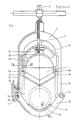
- - la figure 1 représente le coupe-tube objet de l'invention au commencement de la coupe, vue de face avec la moitié gauche vue en coupe.
- - la figure 2 représente la section du coupe-tube suivant A-A.
- - la figure 3 représente une variante de la section du coupe-tube suivant A-A.
- - la figure 4 représente en coupe une autre forme d'arcade inférieure pourvue d'un support de tube constitué de plaques métalliques planes.
- - la figure 5 représente la coupe suivant B-B de l'arcade inférieure.
- - la figure 6 représente la lame du coupe-tube.
- - la figure 7 représente grossie quatre fois la section suivant C-C de la lame du coupe-tube.
- - la figure 8 montre le mode de fixation par pincement de la lame mince.
- - la figure 9 montre un autre mode de fixation de la lame utilisé dans le cas de l'emploi d'une lame épaisse.
- - Figure 1 shows the pipe cutter object of the invention at the beginning of the cut, front view with the left half seen in section.
- - Figure 2 shows the section of the tube cutter along AA.
- - Figure 3 shows a variant of the section of the tube cutter along AA.
- - Figure 4 shows in section another form of lower arch provided with a tube support consisting of flat metal plates.
- - Figure 5 shows the section along BB of the lower arch.
- - Figure 6 shows the blade of the pipe cutter.
- - Figure 7 shows magnified four times the section CC of the blade of the pipe cutter.
- - Figure 8 shows the method of fixing by pinching the thin blade.
- - Figure 9 shows another method of fixing the blade used in the case of the use of a thick blade.
En se reportant à la figure 1, on voit que la lame 1 de ce coupe-tube est montée sur un porte-lame 2 qui se déplace sous l'action d'une vis de commande 3 entre les deux branches parallèles d'une arcade-guide 4 fermée par une arcade inférieure 10 maintenue en place d'un côté par l'axe d'articulation 11 et de l'autre par un dispositif de verrouillage 7 sur lequel on peut agir pour que cette arcade puisse pivoter autour de son axe d'articulation jusqu'à l'ouverture totale ; ce qui permet de placer le coupe-tube directement à cheval sur le tube à sectionner 9. La vis de commande 3 est pourvue d'une tige de manoeuvre 5 et d'un carré d'entraînement 6 permettant soit de la raccorder à un ensemble de motorisation, soit de la faire tourner à l'aide d'une clé de manoeuvre de vanne de conduite enterrée du genre des clés à douille utilisées par les services du Gaz de France. Lorsque la lame de coupe attaque le tube 9 sous la pression de la vis 3 , le banc de section curviligne 8 ou de toute autre forme suivant le profil à couper, vient au contact du tube sur lequel il se plaque obligeant ainsi le coupe-tube à se placer à l'équerre sur ledit tube à sectionner 9 qui serré de cette façon fait office de support du coupe-tube pendant toute la durée de l'opération de coupe.Referring to Figure 1, we see that the
Toujours sur la figure 1 on voit que la partie supérieure du porte-lame 2 reçoit la poussée de la vis de commande 3 par l'intermédiaire d'une butée ou d'une bille en acier 21 tournant sur un grain 22 tandis que la partie inférieure présente entre les deux points de fixation 24, 20 de la lame un évidement semi-circulaire 23 de diamètre légèrement supérieur à celui du plus gros tube à couper.Still in FIG. 1, it can be seen that the upper part of the
En se reportant aux figures 2 et 3 on constate que le guidage du porte-lame 2 entre les deux branches de l'arcade 4 peut être réalisé de deux façons différentes : des portées usinées sont prévues sur les parties extérieures 12, 13 de chaque branche qui doivent être en contact avec le porte-lame pour qu'il puisse glisser dessus (fig.2) ou alors ces portées sont prévues sur les parties intérieures 14, 15 de ces mêmes ailes pour que le porte-lame puisse y coulisser intérieurement. Que l'on retienne le premier mode de guidage ou sa variante de la figure 3, la largeur de la lame de coupe peut être égale à celle du porte-lame 2 comprise entre ses parties saillantes (16) 19 se déplaçant entre les ailes des deux branches de l'arcade-guide 4 visible sur la figure 1. Il en résulte que pour une largeur de lame donnée, l'encombrement de l'arcade-guide est très réduit.Referring to Figures 2 and 3 we see that the guide of the
Pour la coupe des tubes de gros diamètre livrés en touret, l'épaisseur du porte-lame au niveau de l'évidement (23) peut être augmentée jusqu'à être égale à celle du banc (8) de l'arcade inférieure pour qu'en fin de coupe sa forme semi-circulaire vienne envelopper suffisamment le tube sous contrainte de chaque côté de la lame pour empêcher la détente brutale des tronçons sectionnés qui est généralement très dangereuse pour l'opérateur tant les contraintes existant entre la partie déroulée du tube et celle restant sur le touret sont importantes.For cutting large diameter tubes delivered in reels, the thickness of the blade holder at the level of the recess (23) can be increased until being equal to that of the bench (8) of the lower arch so that at the end of the cut its semi-circular shape comes to wrap sufficiently the tube under stress on each side of the blade to prevent sudden expansion of the sectioned sections which is generally very dangerous for the operator as the stresses existing between the unwound part of the tube and that remaining on the reel are important.
La figure 4 avec la coupe suivant B-B représentée figure 5 montre une autre forme d'arcade inférieure dans laquelle le banc de section curviligne a été remplacé par des plaques métalliques planes 25, 26 présentant comme ce dernier une échancrure 27 située dans le plan de coupe de lame pour permettre à ladite lame de venir achever sa course en-dessous desdites plaques en assurant ainsi un sectionnement complet du tube à couper. Cette échancrure 27 devant toujours être libre pour le passage de la lame, une ouverture 28 plus courte et plus large pratiquée suivant le même axe dans la partie la plus basse de l'arcade inférieure empêche les saletés se trouvant éventuellepent sur le tube à couper de venir obstruer ladite échancrure en s'accumulant dans le fond de l'arcade. De plus ce coupe-tube étant un appareil de chantier susceptible d'être utilisé dans des endroits boueux, cette ouverture 28 facilite le nettoyage.Figure 4 with the section along BB shown in Figure 5 shows another form of lower arch in which the curvilinear section bench has been replaced by
La figure 6 montre une lame de coupe dont l'angle au sommet (![]()
![]()
![]()
![]()
En se reportant à la figure 7 on constate que la section de la lame de coupe est symétrique et qu'elle présente une rupture de pente. Cette symétrie est nécessaire pour obtenir une coupe parfaitement d'équerre.Referring to FIG. 7, it can be seen that the section of the cutting blade is symmetrical and that it has a slope break. This symmetry is necessary to obtain a perfectly square cut.
La figure 8 montre le mode de fixation par pincement qui est utilisé pour les lames de coupe de faible épaisseur dites "minces". A cette fin les extrémités inférieures du porte-lame 2 sont pourvues de chapes 30 dont l'élasticité est mise à profit pour obtenir le pincement souhaité de la lame par un simple serrage des vis 31 .FIG. 8 shows the pinch fastening method which is used for thin cutting blades called "thin". To this end, the lower ends of the
La figure 9 montre une variante du mode de fixation plus facile à réaliser mais utilisable seulement dans le cas de l'emploi d'une lame épaisse qui bien que maintenue que d'un côté possède une rigidité suffisante pour ne pas dévier du plan de coupe sous les efforts latéraux rencontrés en utilisation normale.Figure 9 shows a variant of the fixing method easier to perform but usable only in the case of the use of a thick blade which although maintained on one side has sufficient rigidity not to deviate from the cutting plane under the lateral forces encountered in normal use.
Sur les chantiers de travaux publics ce genre de coupe-tube doit pouvoir être transporté d'un endroit à l'autre en toute sécurité. Pour cela lorsque la lame est complètement descendue dans la position recommandée pour le transport, le porte-lame repousse l'axe d'accrochage 32 de l'arcade inférieure dans le fond de la gorge 33 du verrou 7 visible sur la figure 1 et ainsi le déverrouillage permettant l'ouverture de l'arcade par simple pression sur la partie supérieure 34 du verrou 7 est impossible.On public works sites, this type of pipe cutter must be able to be transported from one place to another in complete safety. For this when the blade is completely lowered in the position recommended for transport, the blade holder pushes the
La coupe est rapide car il suffit de remonter la lame en faisant tourner la vis de commande 3 et d'ouvrir le coupe- tube par simple pression sur la partie supérieure du verrou 7 pour pouvoir le refermer sur le tube qui est ensuite sectionné par la descente de la lame sous l'action de la vis de commande que l'on tourne alors en sens inverse.The cut is quick because it suffices to reassemble the blade by turning the
La préhension et le transport des plus gros de ces coupe-tubes selon l'invention peut être améliorée par l'adjonction d'une poignée en forme d'arceau que l'on fixe sur la partie supérieure de l'arcade-guide, ce qui modifie l'esthétique mais n'augmente pas l'encombrement et permet toujours de travailler dans des tranchées étroites dont la largeur peut ne pas excéder 2,5 fois le diamètre du plus gros tube accepté par l'appareil.The gripping and transport of the larger of these pipe cutters according to the invention can be improved by adding a handle in the form of a hoop which is fixed on the upper part of the yoke-guide, this which changes the aesthetics but does not increase the size and still allows you to work in narrow trenches whose width may not exceed 2.5 times the diameter of the largest tube accepted by the device.
Ce coupe-tube à lame guidée est donc un appareil permettant de couper rapidement et en toute sécurité les tubes en polyéthylène et la plupart des tubes en matières plastiques cylindriques ou non difficiles à couper avec les coupe-tubes à molettes. Son domaine d'utilisation est celui de la pose et de l'entretien de ces tubes, notamment l'adduction d'eau, le tubage de canalisation défectueuse et la distribution du gaz.This guided blade pipe cutter is therefore a device allowing to quickly and safely cut polyethylene tubes and most plastic cylindrical or non-difficult plastic tubes to cut with the wheel tube cutters. Its field of use is that of the installation and maintenance of these tubes, in particular the water supply, the defective pipe casing and the gas distribution.
Claims (7)
Applications Claiming Priority (2)
| Application Number | Priority Date | Filing Date | Title |
|---|---|---|---|
| FR8702425 | 1987-02-19 | ||
| FR8702425A FR2611162B3 (en) | 1987-02-19 | 1987-02-19 | TUBE CUTTER WITH GUIDED BLADE FOR CYLINDRICAL OR NON-PLASTIC TUBES |
Publications (3)
| Publication Number | Publication Date |
|---|---|
| EP0279737A2 true EP0279737A2 (en) | 1988-08-24 |
| EP0279737A3 EP0279737A3 (en) | 1990-07-18 |
| EP0279737B1 EP0279737B1 (en) | 1994-01-19 |
Family
ID=9348246
Family Applications (1)
| Application Number | Title | Priority Date | Filing Date |
|---|---|---|---|
| EP88400317A Expired - Lifetime EP0279737B1 (en) | 1987-02-19 | 1988-02-12 | Plastic tube cutting apparatus with a guided cutter |
Country Status (4)
| Country | Link |
|---|---|
| US (1) | US4845849A (en) |
| EP (1) | EP0279737B1 (en) |
| DE (1) | DE3887177T2 (en) |
| FR (1) | FR2611162B3 (en) |
Cited By (3)
| Publication number | Priority date | Publication date | Assignee | Title |
|---|---|---|---|---|
| EP0769355A1 (en) * | 1995-10-07 | 1997-04-23 | Koeitsusho Kabushiki Kaisha | Plastic bottle cutting implement |
| EP3450070A1 (en) * | 2017-08-31 | 2019-03-06 | Wavin B.V. | Handheld pipe cutter comprising a securer and a method of cutting a pipe |
| US10588449B2 (en) | 2017-10-16 | 2020-03-17 | Steven Jay Self | Cutting device |
Families Citing this family (19)
| Publication number | Priority date | Publication date | Assignee | Title |
|---|---|---|---|---|
| CA2048780C (en) * | 1991-08-08 | 1997-12-16 | Edward Joseph Schartinger | Blade for cutting cylindrical structures |
| US5377410A (en) * | 1993-10-25 | 1995-01-03 | Welch; Wade | Cutter for strand-encircling sheaths |
| US5956853A (en) * | 1997-06-10 | 1999-09-28 | Watamura; Abe | Pipe cutting tool for plastic pipe |
| USD435209S (en) * | 1999-10-06 | 2000-12-19 | Armament Systems And Procedures, Inc. | Cutting device |
| US6349472B1 (en) * | 1999-10-06 | 2002-02-26 | Armament Systems And Procedures, Inc. | Cutting device |
| US6671962B2 (en) | 2001-06-04 | 2004-01-06 | Abe Watamura | Pipe cutting tool for plastic pipe |
| NO322114B1 (en) * | 2004-08-24 | 2006-08-14 | Uni For Miljo Og Biovitenskap | pipe cutter |
| CN100460115C (en) * | 2005-01-05 | 2009-02-11 | 叶咏梅 | Adjustable pipe cutter |
| DE112008000686B4 (en) | 2007-03-15 | 2016-07-28 | Milwaukee Electric Tool Corp. | Rohrschneider |
| DE112008003266T5 (en) * | 2007-11-28 | 2010-10-07 | Milwaukee Electric Tool Corp., Brookfield | Rohrschneider |
| BR112012030131B1 (en) * | 2010-05-28 | 2021-03-23 | National Oilwell Varco, L.P. | EXPLOSION PROTECTION VALVE TO CUT A TUBULAR STRUCTURE FROM A DRILLING WELL, METHOD TO CUT A TUBULAR STRUCTURE AND CUTTING TOOL TO CUT A TUBULAR STRUCTURE FROM A DRILLING WELL |
| US8162046B2 (en) | 2010-08-17 | 2012-04-24 | T-3 Property Holdings, Inc. | Blowout preventer with shearing blades |
| US8632047B2 (en) * | 2011-02-02 | 2014-01-21 | Hydril Usa Manufacturing Llc | Shear blade geometry and method |
| RU2598014C1 (en) * | 2015-04-21 | 2016-09-20 | Виктор Сергеевич Быков | Device for cutting pipes from polypropylene |
| USD813006S1 (en) | 2015-06-15 | 2018-03-20 | Milwaukee Electric Tool Corporation | Knob for a cutter |
| CN205218181U (en) | 2015-06-15 | 2016-05-11 | 米沃奇电动工具公司 | Pipeline cutterbar |
| CA2994418C (en) | 2015-08-07 | 2021-07-20 | Lawrence Norman Brown | Portable hand tool and kit |
| CN105058463A (en) * | 2015-08-28 | 2015-11-18 | 岑立强 | Electric horizontal type pipe cutting machine for plastic pipes |
| CN110509331B (en) * | 2019-08-16 | 2021-08-06 | 江西强发科技有限公司 | PVC pipeline cutting structure |
Citations (3)
| Publication number | Priority date | Publication date | Assignee | Title |
|---|---|---|---|---|
| GB378654A (en) * | 1931-09-01 | 1932-08-18 | George Geach Parnall | Improvements in or relating to tube cutting tools |
| US2248642A (en) * | 1938-11-26 | 1941-07-08 | Howard T Saperston | Device for cutting cables and the like |
| US2539124A (en) * | 1949-04-15 | 1951-01-23 | Ellwood W Findlay | Tube cutting device |
Family Cites Families (2)
| Publication number | Priority date | Publication date | Assignee | Title |
|---|---|---|---|---|
| US1156745A (en) * | 1915-05-01 | 1915-10-12 | Joseph D Brady | Tool for splitting nuts. |
| GB277558A (en) * | 1927-02-23 | 1927-09-22 | Samuel Armstrong | An improved apparatus for dehorning cattle |
-
1987
- 1987-02-19 FR FR8702425A patent/FR2611162B3/en not_active Expired
-
1988
- 1988-02-12 EP EP88400317A patent/EP0279737B1/en not_active Expired - Lifetime
- 1988-02-12 DE DE3887177T patent/DE3887177T2/en not_active Expired - Fee Related
- 1988-02-19 US US07/157,787 patent/US4845849A/en not_active Expired - Lifetime
Patent Citations (3)
| Publication number | Priority date | Publication date | Assignee | Title |
|---|---|---|---|---|
| GB378654A (en) * | 1931-09-01 | 1932-08-18 | George Geach Parnall | Improvements in or relating to tube cutting tools |
| US2248642A (en) * | 1938-11-26 | 1941-07-08 | Howard T Saperston | Device for cutting cables and the like |
| US2539124A (en) * | 1949-04-15 | 1951-01-23 | Ellwood W Findlay | Tube cutting device |
Cited By (5)
| Publication number | Priority date | Publication date | Assignee | Title |
|---|---|---|---|---|
| EP0769355A1 (en) * | 1995-10-07 | 1997-04-23 | Koeitsusho Kabushiki Kaisha | Plastic bottle cutting implement |
| US5740612A (en) * | 1995-10-07 | 1998-04-21 | Koeitsusho Kabushiki Kaisha | Plastic bottle cutting implement |
| EP3450070A1 (en) * | 2017-08-31 | 2019-03-06 | Wavin B.V. | Handheld pipe cutter comprising a securer and a method of cutting a pipe |
| NL1042524B1 (en) * | 2017-08-31 | 2019-03-11 | Wavin Bv | Handheld pipe cutter comprising a securer and a method of cutting a pipe |
| US10588449B2 (en) | 2017-10-16 | 2020-03-17 | Steven Jay Self | Cutting device |
Also Published As
| Publication number | Publication date |
|---|---|
| FR2611162A1 (en) | 1988-08-26 |
| EP0279737A3 (en) | 1990-07-18 |
| DE3887177D1 (en) | 1994-03-03 |
| EP0279737B1 (en) | 1994-01-19 |
| DE3887177T2 (en) | 1994-07-21 |
| FR2611162B3 (en) | 1989-06-16 |
| US4845849A (en) | 1989-07-11 |
Similar Documents
| Publication | Publication Date | Title |
|---|---|---|
| EP0279737B1 (en) | Plastic tube cutting apparatus with a guided cutter | |
| FR2860701A1 (en) | DEVICE AND METHOD FOR SECTIONING THE BLADE OF A VERTEBRA | |
| FR2753120A1 (en) | TUBE CLAMP DEVICE FOR TRANSVERSALLY CUTTING A PLASTIC TUBE | |
| EP0532391B1 (en) | Pliers for compressing a pipe, such as a gas duct | |
| FR2775679A1 (en) | CAN OPENER | |
| FR1464371A (en) | Rotor for apparatus intended for the disintegration of straw or similar material | |
| EP1075220A1 (en) | Linking device for surgical instrument | |
| EP0102864A2 (en) | Tube cutter with circular cutters and arches | |
| EP0216683B1 (en) | Tool forming a magazine for installing all kinds of articles, especially for wiring markers | |
| FR2952625A1 (en) | Tool for lifting closure plate utilized for closing e.g. manhole of roadway system, has heel supported on plate for allowing handle to be supported on heel for forming lever arm to facilitate lifting of plate by utilizing tip | |
| FR2698570A1 (en) | Tube cutter with single cutting blade for plastic tubes with high deg. of elasticity - has blade actuated by ratchet mechanism with drive and non-return pawls | |
| EP1466646A1 (en) | Security device against free flow | |
| FR2626441A1 (en) | Machine for peeling and cutting leeks | |
| FR2853617A1 (en) | Cycle e.g. bicycle or tricycle, has fastening device with central part for connecting guidance unit with external parts fixed in handle bar, where guidance unit is inclined in two positions with respect to axis | |
| FR2601548A1 (en) | Mechanical asparagus-harvester with two moving blades | |
| FR3020075B1 (en) | ROTO DENEIGE | |
| FR2510022A1 (en) | Spanner for square headed spindles - uses handle on screw-jack to drive wedge between tail arms of pivotal jaws with V=section grooves | |
| FR2481391A1 (en) | SHEAR PINS COUPLING | |
| FR2758449A1 (en) | Manual device for opening oysters | |
| FR2691387A1 (en) | Tool for restoring cylindrical shape to plastic pipe which has been deformed - has two concave cylindrical jaws operated by screw mechanism or power cylinder | |
| EP0207823A1 (en) | Pliers for opening pressurized jars | |
| FR2632727A1 (en) | Device for taking liquid samples | |
| EP0084496B1 (en) | Means for opening preserving jars under vacuum | |
| BE1006906A5 (en) | Milling tool and device for drilling, drilling for particular wall pipe. | |
| FR2778588A1 (en) | Cutting device for sections, used in the building industry |
Legal Events
| Date | Code | Title | Description |
|---|---|---|---|
| PUAI | Public reference made under article 153(3) epc to a published international application that has entered the european phase |
Free format text: ORIGINAL CODE: 0009012 |
|
| AK | Designated contracting states |
Kind code of ref document: A2 Designated state(s): DE ES FR GB IT |
|
| PUAL | Search report despatched |
Free format text: ORIGINAL CODE: 0009013 |
|
| AK | Designated contracting states |
Kind code of ref document: A3 Designated state(s): DE ES FR GB IT |
|
| 17P | Request for examination filed |
Effective date: 19901024 |
|
| 17Q | First examination report despatched |
Effective date: 19911125 |
|
| GRAA | (expected) grant |
Free format text: ORIGINAL CODE: 0009210 |
|
| AK | Designated contracting states |
Kind code of ref document: B1 Designated state(s): DE ES FR GB IT |
|
| PG25 | Lapsed in a contracting state [announced via postgrant information from national office to epo] |
Ref country code: IT Free format text: LAPSE BECAUSE OF FAILURE TO SUBMIT A TRANSLATION OF THE DESCRIPTION OR TO PAY THE FEE WITHIN THE PRESCRIBED TIME-LIMIT;WARNING: LAPSES OF ITALIAN PATENTS WITH EFFECTIVE DATE BEFORE 2007 MAY HAVE OCCURRED AT ANY TIME BEFORE 2007. THE CORRECT EFFECTIVE DATE MAY BE DIFFERENT FROM THE ONE RECORDED. Effective date: 19940119 Ref country code: ES Free format text: THE PATENT HAS BEEN ANNULLED BY A DECISION OF A NATIONAL AUTHORITY Effective date: 19940119 |
|
| REF | Corresponds to: |
Ref document number: 3887177 Country of ref document: DE Date of ref document: 19940303 |
|
| GBT | Gb: translation of ep patent filed (gb section 77(6)(a)/1977) |
Effective date: 19940308 |
|
| PLBE | No opposition filed within time limit |
Free format text: ORIGINAL CODE: 0009261 |
|
| STAA | Information on the status of an ep patent application or granted ep patent |
Free format text: STATUS: NO OPPOSITION FILED WITHIN TIME LIMIT |
|
| 26N | No opposition filed | ||
| PGFP | Annual fee paid to national office [announced via postgrant information from national office to epo] |
Ref country code: GB Payment date: 19980211 Year of fee payment: 11 |
|
| PGFP | Annual fee paid to national office [announced via postgrant information from national office to epo] |
Ref country code: FR Payment date: 19980227 Year of fee payment: 11 |
|
| PGFP | Annual fee paid to national office [announced via postgrant information from national office to epo] |
Ref country code: DE Payment date: 19980430 Year of fee payment: 11 |
|
| PG25 | Lapsed in a contracting state [announced via postgrant information from national office to epo] |
Ref country code: GB Free format text: LAPSE BECAUSE OF NON-PAYMENT OF DUE FEES Effective date: 19990212 |
|
| GBPC | Gb: european patent ceased through non-payment of renewal fee |
Effective date: 19990212 |
|
| PG25 | Lapsed in a contracting state [announced via postgrant information from national office to epo] |
Ref country code: FR Free format text: LAPSE BECAUSE OF NON-PAYMENT OF DUE FEES Effective date: 19991029 |
|
| PG25 | Lapsed in a contracting state [announced via postgrant information from national office to epo] |
Ref country code: DE Free format text: LAPSE BECAUSE OF NON-PAYMENT OF DUE FEES Effective date: 19991201 |
|
| REG | Reference to a national code |
Ref country code: FR Ref legal event code: ST |